Abstract
Study Design.
Cadaveric laboratory study.
Objective.
To assess the feasibility and accuracy of minimally invasive thoracolumbar pedicle screw placement using augmented reality (AR) surgical navigation.
Summary of Background Data.
Minimally invasive spine (MIS) surgery has increasingly become the method of choice for a wide variety of spine pathologies. Navigation technology based on AR has been shown to be feasible, accurate, and safe in open procedures. AR technology may also be used for MIS surgery.
Methods.
The AR surgical navigation was installed in a hybrid operating room (OR). The hybrid OR includes a surgical table, a motorized flat detector C-arm with intraoperative 2D/3D imaging capabilities, integrated optical cameras for AR navigation, and patient motion tracking using optical markers on the skin. Navigation and screw placement was without any x-ray guidance. Two neurosurgeons placed 66 Jamshidi needles (two cadavers) and 18 cannulated pedicle screws (one cadaver) in the thoracolumbar spine. Technical accuracy was evaluated by measuring the distance between the tip of the actual needle position and the corresponding planned path as well as the angles between the needle and the desired path. Time needed for navigation along the virtual planned path was measured. An independent reviewer assessed the postoperative scans for the pedicle screws’ clinical accuracy.
Results.
Navigation time per insertion was 90 ± 53 seconds with an accuracy of 2.2 ± 1.3 mm. Accuracy was not dependent on operator. There was no correlation between navigation time and accuracy. The mean error angle between the Jamshidi needles and planned paths was 0.9° ± 0.8°. No screw was misplaced outside the pedicle. Two screws breached 2 to 4 mm yielding an overall accuracy of 89% (16/18).
Conclusion.
MIS screw placement directed by AR with intraoperative 3D imaging in a hybrid OR is accurate and efficient, without any fluoroscopy or x-ray imaging during the procedure.
Level of Evidence: N/A
Keywords: accuracy, augmented reality, hybrid operating room, integrated navigation, minimally invasive pedicle screw, occupational radiation dose
Minimally invasive spine (MIS) surgery has many clinical applications and there are predictions that more than half of all spinal procedures will be performed with minimally invasive techniques by 2020.1 There are significant reductions in blood loss, length of hospital stay, and surgical site infection rates in MIS surgery versus open surgery, whereas outcome measurements such as accuracy and complication rates are similar.2–4
Image guidance has been incorporated into MIS surgery to improve the accuracy of pedicle screw placement. Traditionally, 2D intraoperative fluoroscopy has been considered the state-of-the-art method for percutaneous device navigation. However, recent developments in 3D intraoperative imaging associated with navigation have eliminated the need for periprocedural radiation while significantly improving the accuracy of percutaneous pedicle screw placement.5
In recent years, hybrid operating rooms (ORs) that consist of surgical suites with a motorized high-end C-arm system enabling intraoperative 2D/3D imaging have been used to perform spine surgery.6 Augmented reality (AR) technology based on video cameras integrated into the C-arm flat detector frame has been developed as a platform for spine instrument navigation in a hybrid OR set-up with improvement in clinical accuracy relative to open surgery.7
The purpose of this cadaver study was to measure screw placement accuracy and navigation time using AR in a hybrid OR set-up for MIS surgery.
MATERIALS AND METHODS
The study was conducted in compliance with the ethical guidelines for human cadaver studies. Two senior consultant neurosurgeons performed the surgical procedures. Jamshidi needles (CareFusion, Franklin Lakes, NJ) were placed in the thoracic and lumbar spinal levels of two cadavers with no spinal pathologies (cadaver 1: T2-L5 and cadaver 2: T1-L5). Cannulated pedicle screws of size 5 and 5.5 mm (Erisma-MIS, Clariance, France) were inserted in the thoracic spine (T4-T12) of a third cadaver with thoracic compression fractures on vertebrae T5 and T8. The cannulated screws were placed after placing first the K-wires through Jamshidi needles and then the muscle retractors to allow the screwdriver access through the paraspinal muscle. All procedures were performed with the Philips Healthcare AR surgical navigation technology using a minimally invasive approach. The surgery was performed in the craniocaudal direction based on three spinal levels at a time. Each surgeon operated on either spinal side.
The Philips Augmented Reality Surgical Navigation System
The hybrid room was equipped with a Maquet surgical table (Alphamaquet 1150, Maquet AG, Switzerland) connected to a motorized ceiling-mounted C-arm system (AlluraClarity FD20, Philips Healthcare, Best, The Netherlands). The AR system is based on video input from four optical cameras mounted into the frame of the flat detector. Video from all cameras is automatically coregistered with the coordinate system of the C-arm (Figure 1).
Figure 1.
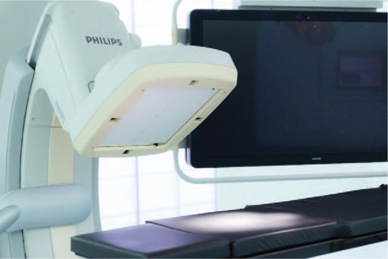
The navigation system consists of a surgical table digitally integrated with a ceiling-mounted motorized C-arm with 2D/3D imaging capabilities and a medical grade monitor where intraoperative imaging is superimposed with the camera images (cf. Figure 2). Note that the cameras are integrated at the middle of each side of the detector housing.
Between 8 and 12 sterile, flat, adhesive circular markers were randomly placed on the skin around the surgical site and were tracked throughout the procedure to compensate for movements.
A 27-cm field of view image was selected to image at least three spinal levels and to perform a 3D Cone Beam computed tomography (CT) acquisition of the desired region of interest (XperCT, Philips Healthcare). The C-arm rotated 180° in 8 seconds during acquisition, creating a 3D volume with 0.45 mm voxel size. The spine was subsequently segmented with identification of the vertebral pedicles and displayed as a 3D volume in addition to multiplanar slice display. Based on the automatic identification of the pedicles, the screw insertion paths were suggested by the system and if necessary adjusted by the operator before insertion.
The optical and intraoperative images were automatically registered with no user interaction required. The C-arm automatically rotated into one of the four possible positions where an optical camera was aligned along the planned axis of insertion. The other three optical cameras provided angulated views for the alignment of the device. The screw path overlaid on the optical camera views depicted the intended device alignment as well as 2D slices or 3D volume rendering from the acquired Cone Beam CT (Figure 2). During screw insertion the optical overlay provided real-time visual feedback of the instrument location with respect to the predefined path. There was no x-ray fluoroscopy during screw placement. The insertion time defined as the time required from skin incision to final needle placement was measured.
Figure 2.
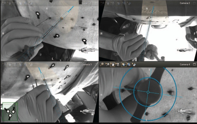
Screenshot of an operator introducing a third Jamshidi needle by aligning it on the skin entry point (camera 4 in the bottom right corner), and using the other three cameras to ensure proper direction of the needle. Note the overlay of intraoperative cone beam computed tomography (CT) slices depicting anatomical information.
Technical and Clinical Accuracy Evaluation
Depending on the angulation of the needles in the spine, the C-arm could be tilted to an adjacent angulation to avoid colinearity between the x-ray beam and the direction of the needles, and thus reducing metal artifacts in the 3D images. The position of the inserted screws relative to the planned path was measured on postoperative 3D scans to assess technical accuracy.8,9 The angular deviation was measured in the axial as well as in the sagittal plane.9–11Figure 3 depicts the technical accuracy and angular deviation measurements.
Figure 3.
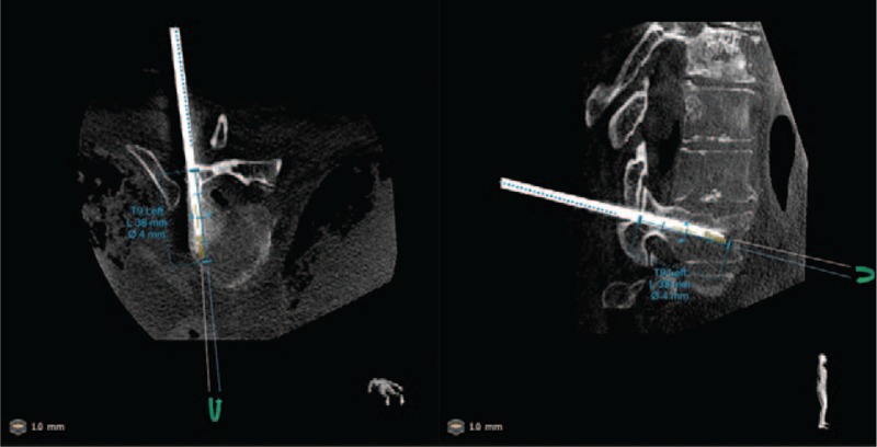
Postoperative cone beam computed tomography (CT) image showing axial and sagittal views of a Jamshidi needle at level T9 (left side) and the corresponding predefined path. In this case, a technical accuracy in the 3D space was 2 mm. Angulation error, being the angle between the predefined path (in blue) and the axis of symmetry of the needle, was measured on both planes and were 0.1 and 0.3 degrees on axial and sagittal planes, respectively.
An independent neurosurgeon assessed screw positions using the Gertzbein grading for clinical accuracy evaluation: grade 0 (screw within the pedicle without cortical breach), grade 1 (0–2 mm breach, minor perforation including cortical encroachment), grade 2 (2–4 mm breach, moderate breach), and grade 3 (more than 4 mm breach, severe displacement).12 The grading was performed on multiplanar (axial, sagittal, and coronal) views (Figure 4).
Figure 4.
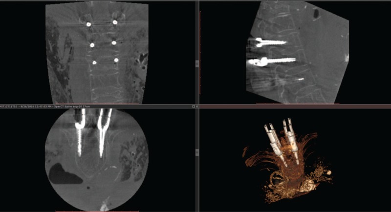
Example of a postoperative intraoperative images of six cannulated screws (bilateral on T10, T11, and T12) for minimally invasive spine (MIS) surgery on coronal (top left), sagittal (top right), and axial (bottom left) planes along with 3D volume rendering (bottom right). Note that there are hardly any metal artifacts despite the presence of six screws and the muscle dilators for each screw that was achieved thanks to the angulated acquisition scan. The axial slice depicts the screws inserted in T12 which both were graded as perfectly inside the pedicle (i.e., grade 0).
Statistical Analysis
Insertion time, accuracy measurement, and angular deviations were expressed as means ± standard deviations and as medians (interquartile ranges). Two-tailed Pearson correlation (ρ) with 95% confidence interval was calculated to identify whether there is correlation between accuracy and navigation time. Two-way analysis of variance and post hoc analysis for multiple comparison correction was used for differentiating navigation accuracy, and navigation time across operators and vertebral levels. Statistical analysis was performed using Matlab (Mathworks, Natick, MA) and a P value less than 0.05 was considered as significant.
RESULTS
The mean technical accuracy between the tip of the navigated device and the planned path was 2.2 ± 1.3 mm (2.0 [1.3–2.6] mm) for the 66 placed Jamshidi needles, following a Gaussian distribution (Figure 5). There was no difference in accuracy between the operators (P = 0.6); however, it differed between spinal levels and was the less at L3 (P < 0.05).
Figure 5.
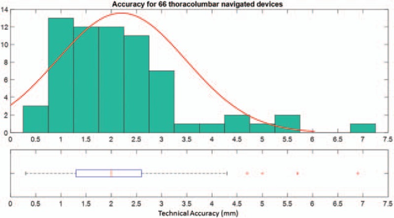
Overall technical accuracy distribution and corresponding box plot indicating median, interquartile, and outliers from the distribution (red crosses).
The mean navigation time following a virtual planned path was 90 ± 53 seconds (75 [56–98] s). The distribution was skewed to lower values with 50% of needle placements performed in less than 75 seconds (Figure 6). There was no difference in navigation time between the operators (P = 0.5) or across spinal levels (P = 0.7).
Figure 6.
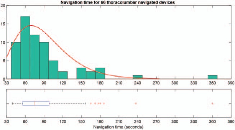
Overall navigation time distribution and corresponding box plot indicating median, interquartile, and outliers from the distribution (red crosses). Note that the distribution is skewed to the lower values.
There was no correlation between accuracy and time to place the needle in the desired position (ρ = 0.17, P = 0.2). The average technical accuracy and navigation time per spinal level is depicted in Figure 7, whereas Table 1 summarizes the accuracy and navigation time per operator.
Figure 7.
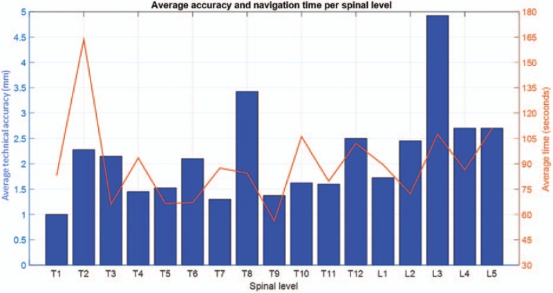
Average technical accuracy and navigation time per spinal level.
TABLE 1.
Technical Accuracy and Navigation Time Per Operator
| Operator 1 | Operator 2 | P | |
| Technical accuracy (mm) | |||
| Mean ± standard deviation | 2.1 ± 1.4 | 2.3 ± 1.1 | 0.6 |
| Median (range) | 2.0 (0.3–6.9) | 2.1 (0.9–5.7) | |
| Navigation time (s) | |||
| Mean ± standard deviation | 94 ± 63 | 85 ± 40 | 0.5 |
| Median (range) | 72 (45–360) | 78 (39–186) | |
Measurements of the axial/sagittal angular deviation between the navigated Jamshidi needle and the planned path were performed showing that both axial and sagittal angular deviations are 0.9° ± 0.8° (0.7 [0.4–1.2]°).
Out of the 18 cannulated pedicle screws which were placed in the third cadaver, no screw was misplaced outside the pedicle and two screws breached 2 to 4 mm yielding an overall clinical accuracy of 89% (16/18). No ionizing radiation was used during navigation or screw placement.
DISCUSSION
Our results indicate that the Philips AR surgical navigation system can be used for percutaneous thoracolumbar pedicle screw placement.
Key steps for pedicle screw placement in MIS surgery are the identification of the starting point for entry into the pedicle, the placement of the Jamshidi needle, and subsequent K-wire. Thus, the first part of this cadaveric study was focused on evaluating the placement of Jamshidi needles using the AR navigation. It was thus assumed that if a surgeon can follow the preplanned path and place the Jamshidi needle correctly, the pedicle screw would be placed accordingly. This is obviously of limited value compared to placing actual pedicle screws and assessing the clinical accuracy. Therefore, the second part of the study was conducted by placing thoracic pedicle screws using the AR navigation to assess clinical accuracy, including pedicle entry definition and screw placement.
The Philips navigation technology utilizes a patient-tracking algorithm that identifies the location of flat adhesive markers placed on the skin. The markers are tracked as long as at least five markers are still visible from any of the four cameras, and thus minimizing the risk for obstruction of the line of sight between the markers and the cameras. Skin surface–based tracking could potentially be a disadvantage in MIS surgery of patients with obesity where there could be a considerable distance between the incision point on the skin and the actual entry point on the vertebra. Thus, small angular errors would be magnified in relation to distance between projected starting point on the skin and true starting point on the bone. This limitation applies to all minimally invasive navigation tools. Methods to resolve this issue include invasive reference points, navigated instruments, and fluoroscopy assistance.
Navigation technologies now evolve from using 2D fluoroscopy to intraoperative 3D-based (including CT) navigation. The cost-effectiveness of various navigation techniques, in relation to their claimed accuracy, is also being explored.13 In our study, the mean navigation time following the virtual planned path was 90 ± 53 seconds with 50% of the procedures performed in less than 75 seconds. This is in line with similar results reported in literature.14 Navigation under conventional fluoroscopy for the same purpose takes longer.15 The technical accuracy in our study is comparable to values from the literature; however, angular deviations are smaller with the present system. Table 2 summarizes the values available in the literature. Although the accuracy in lumbar area (especially at L3 with a technical accuracy of 4.9 mm) was inferior to the other spinal levels; this is still clinically tolerable as the lumbar pedicle isthmus width varies from 8 to 15 mm.16
TABLE 2.
Summary of Articles Reporting Technical Accuracy and Angulation Deviations From Optimum Path of Navigated Screws
| Year-Author (Reference) | Technical Accuracy (mm) | Angulation Error (°) |
| 2016-Kleck et al8 | 5.9 ± 3.5 | 3.1 ± 2.1 (Both axial and sagittal) |
| 2016-Guha et al9 | 1.8 ± 3.6 (Axial) | 3.1 ± 2.9 (Axial) |
| 1.2 ± 1.2 (Sagittal) | 3.6 ± 2.5 (Sagittal) | |
| 2013-Mathew et al10 | Not measured | L4: 2.1 ± 2.6 (Axial) and 2.8 ± 2.1 (sagittal) |
| L5: 2.7 ± 1.9 (axial) and 3.2 ± 2.6 (sagittal) | ||
| 2016-Miller et al11 | Not measured | 2.2 ± 2.2 (Both axial and sagittal) |
| 2011-Scheufler et al17 | Not measured | Ranges between 0 and 4 (axial) |
| This study | 2.2 ± 1.3 | 0.9 ± 0.8 (both axial and sagittal) |
Importantly, a smaller angular deviation between the implant and the planned path yield lower translational error for long paths such as in patients with obesity. Angulation errors increase with the distance between the treated spinal level and the dynamic reference frame, as pointed out by Miller et al11 and Scheufler et al.17 The advantage of having noninvasive skin markers as opposed to a fixed reference frame attached to a spinous process is the possibility of treating multiple levels with consistent accuracy.
Radiation exposure is one of the main hazards surgeons face during MIS procedures.18,19 In a systematic review, Yu and Khan reported that radiation exposure is greater to the surgeon, OR personnel, and patient in MIS procedures as compared to open spine procedures. However, advanced imaging with computer-assisted navigation in MIS procedures can decrease radiation exposure to the surgeon and OR personnel.18 In our study, there was no radiation exposure to the surgeon and OR staff and no lead aprons were required. The patient radiation exposure from cone beam CT with the Philips AR system is considerably less than the radiation dose from a comparable CT scan.
In MIS surgery, the risk for screw malposition or pedicle perforation increases due to lack of visualization of anatomical landmarks. Without navigation, pedicle perforation after percutaneous pedicle screw insertion has been reported to be more than 10%.20,21 A meta-analysis showed an overall perforation risk of 13.1% using 2D fluoroscopic navigation in MIS surgery.5 AR navigation enables the surgeon to place the screws more accurately by providing real-time intraoperative guidance. In our study there was a clinical accuracy of 89%. However, it should be noted that a much larger sample size than the amount of screws used in this study is likely required to eliminate the effect of the learning curve. Furthermore, thoracic pedicles can be as small as 4 mm in size, especially in the midthoracic region. This may explain some of the breaches, because the smallest available screw size for this study was 5 mm.16
Limitations of our study include the small sample size and the fact that we only placed the Jamshidi needles in two specimens. However, a correctly placed K-wire through a Jamshidi needle in the pedicle arguably results in a correct screw placement irrespective of which commercial system might be used. Another limitation, although necessary, is that the study was performed on cadavers and not patients with present spinal pathologies and without movements from breathing.
CONCLUSION
MIS screw placement directed by AR with intraoperative 3D imaging in a hybrid OR is accurate and efficient, without any fluoroscopy or x-ray imaging during the procedure.
Key Points
Minimally invasive thoracic and lumbar pedicle screw placement using an optical-based navigation technology with AR and integrated intraoperative imaging is feasible.
The technical accuracy was 2.2 ± 1.3 mm and was not correlated with the navigation time (90 ± 53 s) nor with the operator.
The overall clinical accuracy of minimally invasive pedicle screw placement with the AR system was similar to published data for open surgery using the same technology (i.e., 89%).
Image acquisition, anatomy assessment, surgical planning, and result verification can be performed during the surgical procedure.
Footnotes
The device that is the subject of this manuscript is not FDA-approved and is not commercially available in the United States.
No funds were received in support of this work.
Relevant financial activities outside the submitted work: employment, travel/accommodations/meeting expenses.
References
- 1.Phillips FM, Cheng I, Rampersaud YR, et al. Breaking through the “glass ceiling” of minimally invasive spine surgery. Spine (Phila Pa 1976) 2016; 41:S39–S43. [DOI] [PubMed] [Google Scholar]
- 2.Varzan M, Gempt J, Meyer B, et al. Minimally invasive transforaminal lumbar interbody fusion versus open transforaminal lumbar interbody fusion: a technical description and review of the literature. Acta Neurochir (Wien) 2017; 159:1137–1146. [DOI] [PubMed] [Google Scholar]
- 3.Goldstein CL, Macwan K, Sundararajan K, et al. Perioperative outcomes and adverse events of minimally invasive versus open posterior lumbar fusion: meta-analysis and systematic review. J Neurosurg Spine 2016; 24:416–427. [DOI] [PubMed] [Google Scholar]
- 4.Lu VM, Kerezoudis P, Gilder HE, et al. Minimally invasive surgery versus open surgery spinal fusion for spondylolisthesis: a systematic review and meta-analysis. Spine (Phila Pa 1976) 2017; 42:E177–E185. [DOI] [PubMed] [Google Scholar]
- 5.Bourgeois AC, Faulkner AR, Bradley YC, et al. Improved accuracy of minimally invasive transpedicular screw placement in the lumbar spine with 3-dimensional stereotactic image guidance: a comparative meta-analysis. J Spinal Disord Tech 2015; 28:324–329. [DOI] [PubMed] [Google Scholar]
- 6.Nevzati E, Fandino J, Schatlo B, et al. Validation and accuracy of intraoperative CT scan using the Philips AlluraXper FD20 angiography suite for assessment of spinal instrumentation. Br J Neurosurg 2017; 10:1–6. [DOI] [PubMed] [Google Scholar]
- 7.Elmi-Terander A, Skulason H, Soderman M, et al. Surgical navigation technology based on augmented reality and integrated 3D intraoperative imaging: a spine cadaveric feasibility and accuracy study. Spine (Phila Pa 1976) 2016; 41:E1303–E1311. [DOI] [PMC free article] [PubMed] [Google Scholar]
- 8.Kleck CJ, Cullilmore I, LaFleur M, et al. A new 3-dimensional method for measuring precision in surgical navigation and methods to optimize navigation accuracy. Eur Spine J 2016; 25:1764–1774. [DOI] [PubMed] [Google Scholar]
- 9.Guha D, Jakubovic R, Gupta S, et al. Spinal intraoperative three-dimensional navigation: correlation between clinical and absolute engineering accuracy. Spine J 2017; 17:489–498. [DOI] [PubMed] [Google Scholar]
- 10.Mathew JE, Mok K, Goulet B. Pedicle violation and navigational errors in pedicle screw insertion using the intraoperative O-arm: a preliminary report. Int J Spine Surg 2013; 7:e88–e94. [DOI] [PMC free article] [PubMed] [Google Scholar]
- 11.Miller CA, Ledonio CG, Hunt MA, et al. Reliability of the planned pedicle screw trajectory versus the actual pedicle screw trajectory using intra-operative 3D CT and image guidance. Int J Spine Surg 2016; 10:38. [DOI] [PMC free article] [PubMed] [Google Scholar]
- 12.Gertzbein SD, Robbins SE. Accuracy of pedicular screw placement in vivo. Spine (Phila Pa 1976) 1990; 15:11–14. [DOI] [PubMed] [Google Scholar]
- 13.Dea N, Fisher CG, Batke J, et al. Economic evaluation comparing intraoperative cone beam CT-based navigation and conventional fluoroscopy for the placement of spinal pedicle screws: a patient-level data cost-effectiveness analysis. Spine J 2016; 16:23–31. [DOI] [PubMed] [Google Scholar]
- 14.Lian X, Navarro-Ramirez R, Berlin C, et al. Total 3D Airo® navigation for minimally invasive transforaminal lumbar interbody fusion. Biomed Res Int 2016; 2016:5027340. [DOI] [PMC free article] [PubMed] [Google Scholar]
- 15.Yang BP, Wahl MM, Idler CS. Percutaneous lumbar pedicle screw placement aided by computer-assisted fluoroscopy-based navigation: perioperative results of a prospective, comparative, multicenter study. Spine (Phila Pa 1976) 2012; 37:2055–2060. [DOI] [PubMed] [Google Scholar]
- 16.Zindrick MR, Wiltse LL, Doornik A, et al. Analysis of the morphometric characteristics of the thoracic and lumbar pedicles. Spine (Phila Pa 1976) 1987; 12:160–166. [DOI] [PubMed] [Google Scholar]
- 17.Scheufler KM, Franke J, Eckardt A, et al. Accuracy of image-guided pedicle screw placement using intraoperative computed tomography-based navigation with automated referencing. Part II: thoracolumbar spine. Neurosurgery 2011; 69:1307–1316. [DOI] [PubMed] [Google Scholar]
- 18.Yu E, Khan SN. Does less invasive spine surgery result in increased radiation exposure? A systematic review. Clin Orthop Relat Res 2014; 472:1738–1748. [DOI] [PMC free article] [PubMed] [Google Scholar]
- 19.Bronsard N, Boli T, Challali M, et al. Comparison between percutaneous and traditional fixation of lumbar spine fracture: intraoperative radiation exposure levels and outcomes. Orthop Traumatol Surg Res 2013; 99:162–168. [DOI] [PubMed] [Google Scholar]
- 20.Schizas C, Michel J, Kosmopoulos V, et al. Computer tomography assessment of pedicle screw insertion in percutaneous posterior transpedicular stabilization. Eur Spine J 2007; 16:613–617. [DOI] [PMC free article] [PubMed] [Google Scholar]
- 21.Kim MC, Chung HT, Cho JL, et al. Factors affecting the accurate placement of percutaneous pedicle screws during minimally invasive transforaminal lumbar interbody fusion. Eur Spine J 2011; 20:1635–1643. [DOI] [PMC free article] [PubMed] [Google Scholar]


