Abstract
We assessed labeling region selectivity on time-spatial labeling inversion pulse (Time-SLIP) with pencil beam pulse (PB Time-SLIP) for the use of visualizing cerebrospinal fluid (CSF) flow dynamics. We compared the selectivity of labeling to the third and fourth ventricles between PB Time-SLIP and conventional Time-SLIP (cTime-SLIP) in eight volunteers and one patient using a 1.5T MRI. PB Time-SLIP provided more selective labeling in CSF than cTime-SLIP, particularly in complex anatomical regions.
Keywords: time-spatial labeling inversion pulse, cerebrospinal fluid, pencil beam pulse, two-dimensional pulse, flow dynamics
Introduction
The process of cerebrospinal fluid (CSF) flow dynamics involves absorption and production. However, the entire process has not been completely elucidated.1 Conventionally, CSF flow dynamics have been assessed by computed tomography cisternography and radionuclide cisternography. MRI can also be used and is noninvasive. CSF flow has been assessed using a phase-contrast technique.2 Because MRI can provide images regarding CSF flow without administering contrast agents, it has the advantage of showing the CSF in its physiological state.
Recently, Yamada et al.3 reported a method of observing CSF flow dynamics using time-spatial labeling inversion pulse (Time-SLIP), which allows shorter acquisition times than the phase-contrast technique. They demonstrated that the diagnostic performance of the Time-SLIP technique for patients with hydrocephalus was comparable to that of the phase-contrast technique. For example, Time-SLIP images showed the characteristic disappearance of CSF exchange between the lateral ventricles and the third ventricle through the foramen of Monro in patients with hydrocephalus.3 This technique has been reported to be as useful as the phase-contrast technique for visualizing CSF motion.4 The Time-SLIP technique has often been applied for non-contrast magnetic resonance angiography (e.g., selectively visualizing pulmonary arteries),5 and it contributes to making a morphological diagnosis by enabling the selective visualization of the target region and to making a functional diagnosis by observing the hemodynamics of the target. For example, this technique can be useful for showing faster flow at the cerebral aqueduct in patients with hydrocephalus by changing the parameters of the time inversion (TI) delay.3 However, the Time-SLIP technique has a limitation in that CSF flow dynamics can only be observed in the definite labeled area using a conventional one-dimensional labeling pulse.
The use of a pencil beam (PB) (i.e., two-dimensional [2D]) radiofrequency (RF) pulse to excite a spatially restricted volume6 may enable the more selective excitation of nuclear proton spins. A PB pulse has not been used for imaging techniques and is mostly used for navigation applications.7 Recently, this technique has been introduced in arterial spin labeling (ASL) and provides perfusion territory mapping.8
Here, we propose a novel technique involving a PB pulse combined with Time-SLIP (PB Time-SLIP) that may enable the more selective labeling for the use of visualizing CSF flow dynamics. The purpose of this study was to compare the selectivities of CSF flow between PB Time-SLIP and conventional Time-SLIP (cTime-SLIP).
Materials and Methods
Magnetic resonance imaging
All examinations were performed on a 1.5T scanner (Achieva R2; Philips Healthcare, Best, the Netherlands). This system can operate at a maximum slew rate of 160 mT/m/ms and a maximum gradient strength of 66 mT/m. An 8-channel receive-only head coil was used to cover the whole brain area.
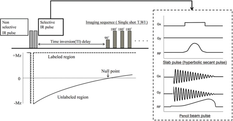
The basic principle of the Time-SLIP sequence is illustrated in Fig. 1. Time-SLIP is a type of ASL technique that enables the visualization of flow dynamics of the target tissue by combining a non-selective inversion recovery (IR) pulse and a selective IR pulse. First, a non-selective IR pulse is applied to invert all spins of protons in the imaging area. Second, a spatially selective IR pulse is applied to invert the spins of the target tissue again, and imaging data are acquired after the labeling spins flow out. The longitudinal magnetization of spins outside the labeled region recovers, depending on the spin-lattice relaxation times of T1 at each tissue. Therefore, the spins outside the labeled region appear as low-signal areas when the data are acquired at the near null point. This time until data acquisition, termed as the TI delay, has two important roles: 1) background signal suppression and 2) the labeled spins travel from the labeled region. With the conventional Time-SLIP technique, a slab pulse is commonly used, such as slice excitation. In this study, a hyperbolic secant pulse, which has been known to be less affected by B1 inhomogeneity,9 was used for the slab pulse on cTime-SLIP and non-selective pulse on both Time-SLIP; while the 16 turn spiral gradient waveform with a constant angular rate and RF modulation was used for the selective pulse on PB Time-SLIP. Although a PB pulse can excite a spatially restricted volume, it needs a 2D gradient waveform, which results in the prolongation of the RF irradiation time relative to that of a slab pulse.6 This characteristic of a PB pulse becomes more remarkable when a narrow pulse width of RF is used.
Fig. 1.
Schematic overview of time-spatial labeling inversion pulse (Time-SLIP). Time-SLIP is based on an arterial spin labeling technique and provides information on flow dynamics. This technique requires a set of two pulses, including selective and non-selective pulses, for spin labeling. The selective pulse is used to label the target region. IR, inversion recovery; T2WI, T2-weighted image.
Basic Time-SLIP images were obtained under the following conditions: 2D single-shot T2-weighted imaging, repetition time = 6000 ms, echo time = 83 ms, flip angle = 90°, field of view = 250 × 250 mm2, matrix = 256 × 256, slice thickness = 5 mm, turbo spin echo factor = 97, half scan factor = 0.6, sensitivity encoding factor = 1.6, TI = 2500 ms, k-space trajectory = sequential order, and selective pulse width = 30 mm. The TI value was set close to the null point of the CSF, as reported by Yamada et al.3 Time-SLIP image was performed with peripheral pulse unit (PPU) synchronized dynamic MRI (a total of 10 images). Total scan time was about 2 minutes.
Phantom experiments
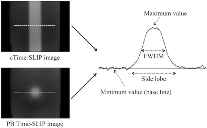
To assess the effect of the side lobe, a preliminary phantom study was performed using basic Time-SLIP sequence with PB pulse or slab pulse. The phantom consisted of distilled water in a polypropylene container (8 × 15 × 5 cm). cTime-SLIP and PB Time-SLIP were performed with a variable selective pulse width ranged from 10 mm to 50 mm in five steps under the parameters described above. Both Time-SLIP was scanned in the coronal plane. The full width at half maximums (FWHM) and the side lobe were measured on the first phase of the dynamic images (Fig. 2). The profile position was determined at the maximum diameter of the pencil beam pulse. The same profile position was also used for cTime-slip. The baseline was determined as minimum plateau on each profile. The minimum value was determined by averaging the signal value at 10 pixels on the baseline to obtain a stable signal. The FWHM was defined as the distance between the points at which signal on the profile reached 50% of the maximum value from the minimum value. The side lobe was defined as the distance between the points at which the profile reached to the minimum value at both ends (Fig. 2).
Fig. 2.
A schema for signal profile for measuring the side lobe and the full width at half maximums (FWHM). The signal profile was obtained at the dash line on each time-spatial labeling inversion pulse (Time-SLIP) image. cTime-SLIP, conventional Time-SLIP; PB Time-SLIP, time-spatial labeling inversion pulse with pencil beam pulse.
Human experiments
Eight healthy volunteers (six males and two females; age range, 25 to 37 years; mean age 27.5 ± 4.1 years) and one patient after endoscopic third ventriculostomy for aqueduct obstruction caused by a hematoma were examined. This study protocol was approved by the institutional review boards of the participating institutions, and written informed consent was obtained from all participants.
The two types of labeling pulses were applied to regions of the fourth ventricle on mid-sagittal images in the healthy volunteers (Fig. 3). In order to make maximum use of the selectivity of pulse, labeling pulse was implemented perpendicular to the imaging slice. The selective pulse irradiation time used in the volunteer study was 6.8 ms for the slab pulse and 7.3 ms for the PB pulse.
Fig. 3.
The position and orientation of labeling pulse versus brain anatomy: conventional time-spatial labeling inversion pulse (Time-SLIP) (a) and Time-SLIP with pencil beam pulse (b). The each labeling pulse perpendicular to the mid-sagittal image was placed to regions of the fourth ventricle.
In the clinical case, PB labeling pulse width set to 15 mm were applied to the posterior, middle, and anterior portions of the third ventricle on mid-sagittal images. Because the third ventricle was a relatively narrow anatomical structure, the labeling pulse width was set narrower than that in the volunteer study. Under this condition, the selective pulse irradiation time was 11.5 ms for the PB pulse.
Image assessment
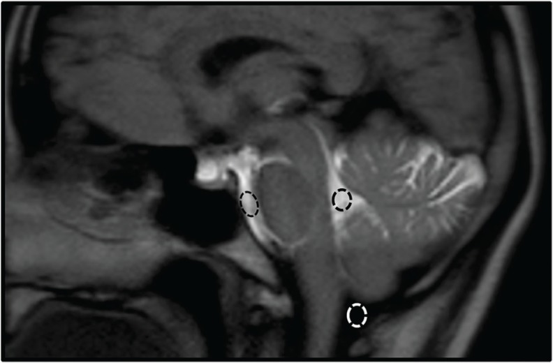
The accuracy of labeling was assessed because the inversion efficiency is assumed to be less in PB Time-SLIP than in cTime-SLIP. The contrast between the labeled CSF and background tissue (e.g., brain tissue and unlabeled CSF) is important for the visibility of CSF flow dynamics in the Time-SLIP technique. To evaluate the contrast in PB Time-SLIP and cTime-SLIP, the signal intensities in the prepontine cistern (PC), cisterna magna (CM), and fourth ventricle (FV) were measured (Fig. 4). ROIs were placed on each ventricle by one of the authors (S.S). The size of each ROI was drawn at least 25 pixels on the first phase of the dynamic images. The signal intensity ratio (SIR) was calculated as the contrast indicator, according to the following equation (1):
| (1) |
where S1 is the signal of the CSF in the FV, and S2 is the signal in the PC or CM.
Fig. 4.
An image showing an example of ROI settings. ROIs were set in the prepontine cistern (PC), cisterna magna (CM), and fourth ventricle (FV) on time-spatial labeling inversion pulse (Time-SLIP) images of the mid-sagittal section.
Differences in each SIR between PB Time-SLIP and SP Time-SLIP were assessed using the Wilcoxon signed-rank test. Statistical analysis was performed using MedCalc version 12.2.1 (MedCalc Software, Mariakerke, Belgium). P values < 0.05 were considered to indicate a statistically significant difference.
Results
Phantom experiments
Table 1 summarizes the FWHM and the side lobe in the phantom experiments. For cTime-SLIP, the difference between the setting pulse width and the FWHM of cTime-SLIP was only 0.42 mm even at the maximum error; the side lobe from the edge of the setting pulse width was 2.14 to 5.09 mm. For PB Time-SLIP, on the other hand, the minimum error between the setting pulse width and the FWHM of PB Time-SLIP was 0.82 mm when the pulse width set to 10 mm; the side lobe from the edge of the setting pulse width was 4.69 to 6.62 mm.
Table 1.
The full width at half maximums (FWHM) and the side lobe on each time-spatial labeling inversion pulse (Time-SLIP) sequence in the phantom experiments
| Methods | cTime-SLIP | PB-Time-SLIP | ||||||||
|---|---|---|---|---|---|---|---|---|---|---|
| The width of the selective pulse (mm) | 10 | 20 | 30 | 40 | 50 | 10 | 20 | 30 | 40 | 50 |
| FWHM (mm) | 10.20 | 20.40 | 29.58 | 39.78 | 49.98 | 9.18 | 17.34 | 25.50 | 32.64 | 38.76 |
| The side lobe (mm) | 14.28 | 25.50 | 36.72 | 49.98 | 60.18 | 19.38 | 32.64 | 42.84 | 52.02 | 63.24 |
cTime-SLIP, conventional time-spatial labeling inversion pulse; PB Time-SLIP, time-spatial labeling inversion pulse with pencil beam pulse; FWHM, the full width at half maximums.
These results indicated that the selective pulse more accurately irradiated on cTime-SLIP than PB Time-SLIP.
Human experiments
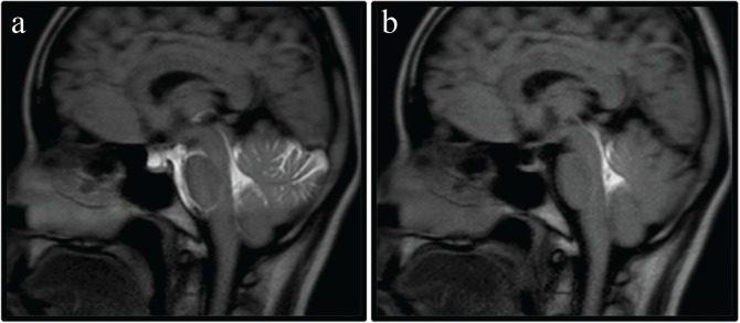
The mid-sagittal images of each Time-SLIP technique are shown in Fig. 5. PB Time-SLIP enabled more selective visualization of CSF flow dynamics than cTime-SLIP. The results of the statistical analysis in SIRs are summarized in Table 2. Regarding the comparison of the SIRs between cTime-SLIP and PB Time-SLIP, SIRFV/PC was significantly higher for PB Time-SLIP than for cTime-SLIP (P = 0.012). SIRFV/CM was not significantly different between the two techniques (P > 0.05).
Fig. 5.
Time-spatial labeling inversion pulse (Time-SLIP) images for observing cerebrospinal fluid (CSF) flow dynamics using conventional Time-SLIP (a) and Time-SLIP with pencil beam pulse (b). Although two types of labeling pulses were applied to the fourth ventricle, CSF flow from the fourth ventricle was more selectively observed using the pencil beam pulse than using the conventional slab pulse.
Table 2.
Comparisons of the mean SIR [± standard deviation (SD)] between the signal of the CSF in the FV and that in the PC or CM obtained using two Time-SLIP sequences in the healthy volunteers (n = 8)
| Methods | cTime-SLIP | PB-Time-SLIP | P value |
|---|---|---|---|
| SIRFV/PC | 1.03 ± 0.09 | 34.88 ± 14.19 | 0.012 |
| SIRFV/CM | 66.37 ± 18.50 | 70.39 ± 24.05 | 0.575 |
CM, cisterna magna; cTime-SLIP, conventional time-spatial labeling inversion pulse; FV, fourth ventricle; PB Time-SLIP, time-spatial labeling inversion pulse with pencil beam pulse; PC, prepontine cistern; SIR, signal intensity ratio.
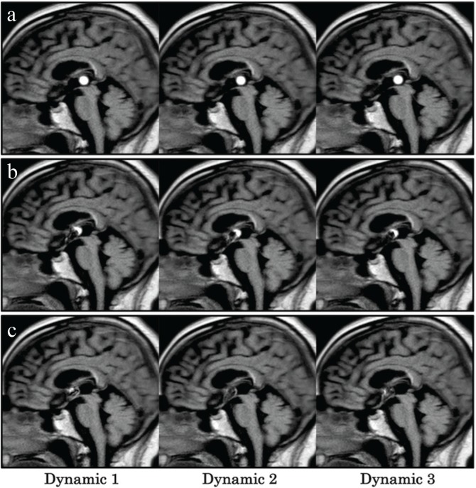
Fig. 6 shows the CSF flow dynamics of the patient after endoscopic third ventriculostomy. In cases involving application of the labeling pulse to the posterior portion of the third ventricle, a circular high-signal region was seen, which was considered to be a characteristic of the PB pulse. PB Time-SLIP with labeling of the middle portion of the third ventricle showed the high-signal region as a semicircle; moreover, PB Time-SLIP with the labeling of the anterior portion of the third ventricle did not show a circular high-signal region.
Fig. 6.
Time-spatial labeling inversion pulse (Time-SLIP) with pencil beam pulse dynamic images (the first–third dynamic images) of a patient after endoscopic third ventriculostomy for cerebral aqueduct occlusion caused by a hematoma. The labeling pulses were applied to the posterior (a), middle (b), and anterior (c) portions of the third ventricle.
Discussion
In the phantom study, the side lobe on PB Time-SLIP was slightly wider than that on cTime-SLIP. In addition, the FWHM on PB Time-SLIP was narrower than the setting pulse width. These findings suggest that the PB Time-SLIP has a wide side lobe, compared with cTime-SLIP, affecting the signals outside the labeling region. However, these effects may be limited in nearby region. In fact, there were no significant differences in SIRFV/CM between cTime-SLIP and PB Time-SLIP in the volunteer study. Since the side lobe was approximately 43 mm using 30 mm selective pulse width on PB Time-SLIP in the volunteer study, the effect of side lobe of labeling to FV should be minimal at CM. Moreover, Because SIRFV/PC was significantly higher in PB Time-SLIP than in cTime-SLIP, the former enabled more selective labeling of the CSF than the latter. PB Time-SLIP maintained a high contrast between the FV and PC, that is, this result also suggests that a PB pulse does not affect areas other than the adjacent region to the target. The most important point in this method is to make the imaging contrast for observing CSF motion. Therefore, a slight influence by wide side lobe on PB Time-SLIP is not considered to be a significant reduction of the imaging quality in most cases. However, we only measured the signal of PC, CM and FV in this study. These regions are sufficiently apart from each other so that the effect of side lobe can be neglected. In the case of measuring the point close to labeling region, the contrast between labeling region and background may be inferior.
Because the CSF has pulsatile flow, the efficacy of labeling may possibly be different between cTime-SLIP and PB Time-SLIP. However, the SIRFV/CM, of PB Time-SLIP was not significantly different from that of cTime-SLIP in our volunteer study. Silver et al.9 reported that a hyperbolic secant pulse has a high inversion efficiency. Therefore, all spins should be inverted first by a non-selective inversion recovery pulse. When a PB is set to a narrow width, the irradiation time extends greatly. For example, if the width of a PB pulse is changed from 60 mm to 15 mm, the irradiation time becomes approximately twice as long. However, this phenomenon does not become prominent in hyperbolic secant pulse under the conditions of this experiment. A long-duration RF pulse cannot be used to label moving objects. However, Davies et al.8 evaluated a PB pulse in ASL and reported that the inversion efficiency decreased by only 5% even at a flow rate of 80 cm/s. The maximum velocity of CSF in patients with idiopathic normal pressure hydrocephalus (iNPH) has been found to be only 25.84 cm/s.10 Moreover, the inversion efficiency has been reported to decrease to 52% in the pulsatile artery in a simulation study, particularly in the systolic phase.8 The reduction of the labeling efficiency should be minimized in the CSF because the CSF is considered to exhibit a much lesser pulsation than the arterial flow. PB Time-SLIP can provide acceptable performance for labeling to the CSF. In addition, we considered that PB Time-SLIP is superior to cTime-SLIP in selective labeling because it enabled the more precise evaluation of CSF dynamics, particularly in complex anatomical regions with CSF. Moreover, a PB pulse can make the Time-SLIP technique sensitive to CSF flow in two dimensions.
We used PB Time-SLIP to assess the CSF flow dynamics of a patient who underwent endoscopic third ventriculostomy. When the posterior portion of the third ventricle was labeled, the signal intensity remained concentrically on the PB Time-SLIP image. Therefore, the CSF flow showed very little flow between the third and fourth ventricles through the aqueduct. As the labeling region shifted from the posterior portion to the anterior portion of the third ventricle, the circular high signal became a semicircle and finally disappeared, which enabled the visualization of turbulent CSF flow between the foramen of Monro and the third ventricle. Analysis of the third ventricle by phase-contrast MRI has been reported;11 however, cTime-SLIP makes it difficult to label only the third ventricle. On the other hand, PB Time-SLIP enables the dynamic ultra-selective observation of CSF flow by improving selectivity in the third ventricle. Thus, this technique can provide a clinical benefit for the detailed assessment of CSF dynamics. Here, a narrow width of PB pulse should be carefully used. If the proton of the CSF labeled by PB pulse was too few using a narrow pulse, observing CSF flow dynamics may be difficult due to flow out to the other ventricular space. Although more selective labeling is useful in complex anatomical regions in clinical practice, the risk of less visibility of labeling using a narrow PB pulse must be taken into account when a patient with the fast CSF flow is scanned.
We were unable to perform a more detailed investigation of various conditions, such as faster CSF flow. The performance of this technique should be assessed to determine if it is robust in patients with intracranial abnormalities, including iNPH, idiopathic intracranial hypertension, and Arnold Chiari malformation. In addition to the PC methods, Horie et al.12 reported a novel method using the dynamic improved motion-sensitized driven-equilibrium steady-state free precession technique for observing irregular CSF motion. PB Time-SLIP technique should be compared these techniques of observing CSF flow dynamics.
Conclusion
PB Time-SLIP enabled the ultra-selective labeling in CSF for the use of observing flow dynamics because of its improved labeling pulse selectivity relative to that of cTime-SLIP, i.e., only the third and fourth ventricles.
Footnotes
Conflicts of Interest
The authors declare that they have no conflicts of interest.
References
- 1.Oresković D, Klarica M. The formation of cerebrospinal fluid: nearly a hundred years of interpretations and misinterpretations. Brain Res Rev 2010; 64:241–262. [DOI] [PubMed] [Google Scholar]
- 2.Nitz WR, Bradley WG, Watanabe AS, et al. Flow dynamics of cerebrospinal fluid: assessment with phase-contrast velocity MR imaging performed with retrospective cardiac gating. Radiology 1992; 183:395–405. [DOI] [PubMed] [Google Scholar]
- 3.Yamada S, Miyazaki M, Kanazawa H, et al. Visualization of cerebrospinal fluid movement with spin labeling at MR imaging: preliminary results in normal and pathophysiologic conditions. Radiology 2008; 249:644–652. [DOI] [PubMed] [Google Scholar]
- 4.Hirayama A, Matsumae M, Yatsushiro S, Abdulla A, Atsumi H, Kuroda K. Visualization of pulsatile CSF motion around membrane-like structures with both 4D velocity mapping and time-sLIP technique. Magn Reson Med Sci 2015; 14:263–273. [DOI] [PubMed] [Google Scholar]
- 5.Hamamoto K, Matsuura K, Chiba E, Okochi T, Tanno K, Tanaka O. Feasibility of non-contrast-enhanced MR angiography using the Time-SLIP technique for the assessment of pulmonary arteriovenous malformation. Magn Reson Med Sci 2016; 15:253–265. [DOI] [PMC free article] [PubMed] [Google Scholar]
- 6.Hardy CJ, Cline HE, Bottomley PA. Correcting for non-uniform k-space sampling in two-dimensional NMR selective excitation. J Magn Reson 1990; 87:639–645. [Google Scholar]
- 7.Wang Y, Rossman PJ, Grimm RC, Riederer SJ, Ehman RL. Navigator-echo-based real-time respiratory gating and triggering for reduction of respiration effects in three-dimensional coronary MR angiography. Radiology 1996; 198:55–60. [DOI] [PubMed] [Google Scholar]
- 8.Davies NP, Jezzard P. Selective arterial spin labeling (SASL): perfusion territory mapping of selected feeding arteries tagged using two-dimensional radiofrequency pulses. Magn Reson Med 2003; 49:1133–1142. [DOI] [PubMed] [Google Scholar]
- 9.Silver MS, Joseph RI, Hoult DI. Highly selective π/2 and π pulse generation. J Magn Reson 1984; 59:347–351. [Google Scholar]
- 10.Sharma AK, Gaikwad S, Gupta V, Garg A, Mishra NK. Measurement of peak CSF flow velocity at cerebral aqueduct, before and after lumbar CSF drainage, by use of phase-contrast MRI: utility in the management of idiopathic normal pressure hydrocephalus. Clin Neurol Neurosurg 2008; 110:363–368. [DOI] [PubMed] [Google Scholar]
- 11.Kurtcuoglu V, Soellinger M, Summers P, et al. Computational investigation of subject-specific cerebrospinal fluid flow in the third ventricle and aqueduct of Sylvius. J Biomech 2007; 40:1235–1245. [DOI] [PubMed] [Google Scholar]
- 12.Horie T, Kajihara N, Matsumae M, et al. Magnetic resonance imaging technique for visualization of irregular cerebrospinal fluid motion in the ventricular system and subarachnoid space. World Neurosurg 2017; 97:523–531. [DOI] [PubMed] [Google Scholar]


