Abstract
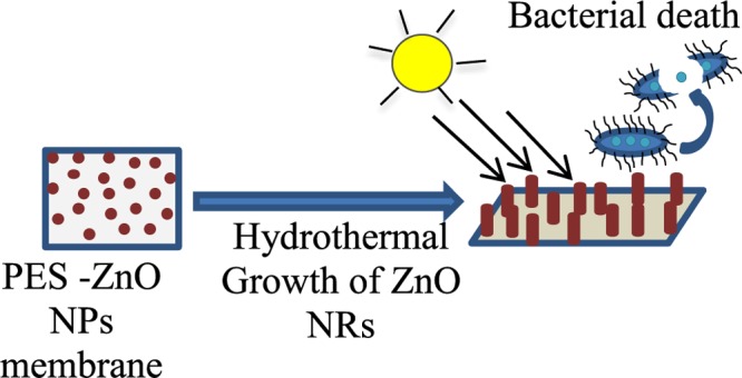
Composite poly(ether sulfone) membranes integrated with ZnO nanostructures either directly blended or grown in situ have enhanced antibacterial activity with improved functionality in reducing the biofouling in water treatment applications. The pore structure and surface properties of the composite were studied to investigate the effect of the addition of ZnO nanostructures. The hydrophilicity of the blended membranes increased with a higher content of ZnO nanoparticles in the membrane (2–6%), which could be further controlled by varying the growth conditions of ZnO nanorods on the polymer surface. Improved water flux, bovine serum albumin rejection, and inhibition of Escherichia coli bacterial growth under visible light irradiation was observed for the membranes decorated with ZnO nanorods compared to those in the membranes simply blended with ZnO nanoparticles. No regrowth of E. coli was recorded even 2 days after the incubation.
1. Introduction
The membrane separation processes in water treatment is of global interest to provide clean water for the growing population across the world.1 Polymeric membranes are dominant in conventional membrane desalination and water treatment applications.1 Among the variety of polymeric membranes that are commercially available, poly(ether sulfone) (PES) membranes are the preferred choice in water treatment plants because of their outstanding thermal stability and mechanical properties.2,3 The PES membranes find application in ultrafiltration, nanofiltration, reverse osmosis, gas separation, and biomedical applications, among others.4 PES (Figure 1) is an amorphous polymer consisting of phenylene rings linked with sulfone groups (−SO2−) or ether linkages (−O−), rendering the polymer chemically resistant with a high glass-transition temperature (∼230 °C).2 However, PES is a moderately hydrophobic polymer, resulting in the membrane being susceptible to biofouling and microbial attacks.5
Figure 1.
PES structure.
Biofouling of the PES membranes is caused by the deposition of natural organic matter, like humic acid, and/or by microorganisms, such as bacteria and microalgae, at the membrane’s surface.6−10 For example, biofouling poses a serious obstacle for water treatment and in desalination plants responsible for the reduction of rejection and net water flux. Enhanced biofouling resistance of the PES membrane has been demonstrated to be achieved by the modification of the PES surfaces to avoid biofouling.8,9,11,12 To minimize the effect of biofouling, feed solutions (especially feed water during desalination) are often pretreated by a chlorination step.8,13,14 However, chlorination degrades the membrane integrity upon frequent use, and the chlorine byproducts generated during the treatment are often dangerous to human health and can contribute adversely to the environment.15 Thus, there is a strong need for membrane modification technologies to overcome the biofouling problem and increase the membrane life time.
Many researchers have been studying the effect of adding organic5,16−21 and inorganic22−28 modifiers to relieve the defects in the currently available membranes.29−31 These additives can be used as surface coatings19,21,22,28,32 or blended3,26,33,34 within the membrane structure. Among the studied membrane modifiers, zinc oxide is considered to be a promising candidate for the fabrication of functionalized composite membranes.26,33,35−37 Zinc oxide is a semiconductor3 that has been widely used in photocatalytic water treatment38−40 to degrade organic pollutants and is known to inhibit the growth of a wide range of microorganisms, such as bacteria Escherichia coli,6,17Bacillus subtilis6 fungi,41 and microalgae.42 Because of the hydrophilic nature of zinc oxide and its microbial activities, it is a suitable material for preparing mixed matrix composite membranes with a high biofouling resistance.43
Recently, Rajabi et al.3 have studied the influence of the shape of ZnO nanostructures on reducing the membrane fouling. Both ZnO nanoparticles and nanorods blended in the membrane showed a reduction in membrane fouling, but the best biofouling reduction was achieved by embedding the PES membrane with ZnO nanorods. However, to the best of our knowledge, no systematic study has been reported on in situ growth of ZnO nanorods on PES membranes and its consequences on membrane properties, microstructure, and antibacterial properties. The aim of this work was to investigate the effect of blending ZnO nanoparticles in PES membranes, followed by in situ growth of ZnO nanorods, and a study of their ability to reduce E. coli bacterium attachment onto the membranes. The antibacterial activity of the ZnO nanoparticle-blended PES membranes are compared to the activity of the membranes with in situ-grown ZnO nanorods.
2. Results and Discussion
2.1. Membrane Characterization
The cross section of all of the membranes (Figure 2) shows an asymmetric structure composed of a thin skin top layer and a thick fingerlike bottom layer. The pore structure of the membranes consists of a dense top layer of small-sized pores that increase in size through the thickness of the membrane forming microvoids and fingerlike structures. This phenomenon was observed earlier upon the inclusion of silica nanoparticles by Huang et al.44
Figure 2.
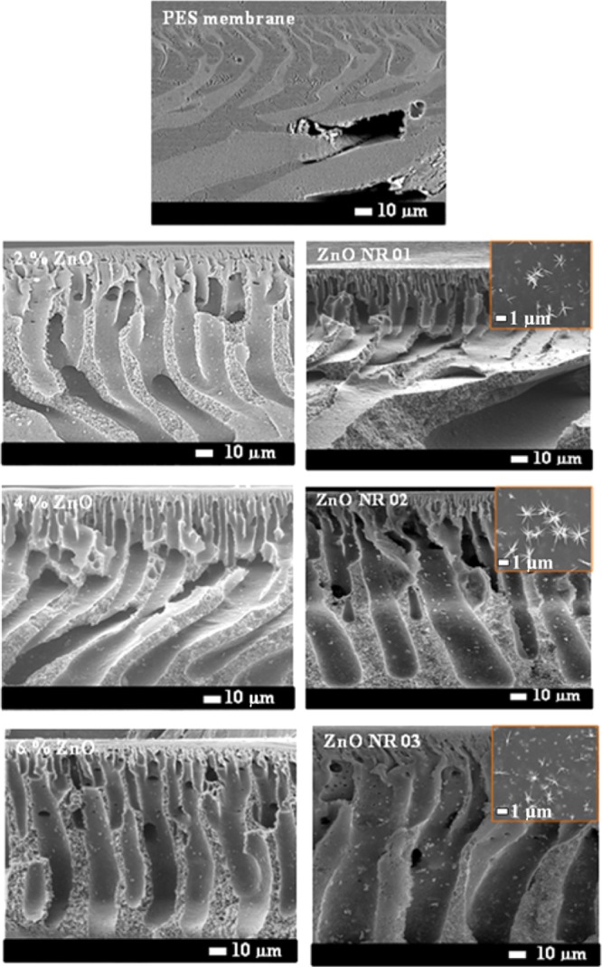
Scanning electron microscope images of PES–ZnO membranes cross section and the top surface at the insight.
Because of the hydrophilic in nature of ZnO nanoparticles, they tend to reside on the top surface of the PES membranes to escape with water during the film formation stage, thus reducing the surface tension, which can lead to the joining of pores in the membranes, forming larger microvoids at the bottom. As the loading of zinc oxide nanoparticles was increased from 2 to 6%, the viscosity of the polymer-doped solution increased, making the water–solvent exchange slower and rendering the pores to align vertically. The viscosity of the PES and ZnO–PES-doped solutions showed Newtonian behavior, which was determined from the slope of the shear stress–shear rate curves as shown in Figure S1. The linearly fitted data of these curves are tabulated in Table S1.
Hydrothermal growth of ZnO nanorods has been reported extensively in literature.45−47 Zinc nitrate is the Zn2+ source in our case, and hexamine hydrolyses slowly in the solution to give OH–. The slow release of hydroxyl ions is required for the controlled precipitation of ZnO to form oriented rods in the direction of the (001) plane.46,48
| 1 |
| 2 |
| 3 |
During the first 4 h of growth, Zn2+ is consumed in the formation of an intermediate state, which is Zn(OH)+ or Zn(OH)2, depending on the pH of the precursor solution. Through gradual hydrolysis of hexamine, the pH of the solution is increased.49 The stability of the intermediate state is reduced by the increase in the solution pH, the reverse reaction is favored, leading to the dissolution of the intermediate phase and precipitation to the more stable phase ZnO(s).49 Zinc oxide dissolution bulk solubility product constant (1.7 × 10⁻¹⁷ mol3 L–3) occurs over a wide range of pH.50 It is well known that supersaturation is necessary for crystal growth in the solution; thus, in our system, the erosion of ZnO nanocrystallites should stop when the process achieves equilibrium
| 4 |
During nanorod growth, the solution is supersaturated, which suggests that erosion and growth proceed simultaneously when the reaction achieves an equilibrium. As the erosion time increases, the concentration of Zn(OH)n2–n(aq) increases and approaches critical supersaturation. Peterson and Gregg51 and Yamabi and Imai52 reported that Zn(OH)n2–n(aq) can form polyhydroxyl zinc complex, which is represented by
| 5 |
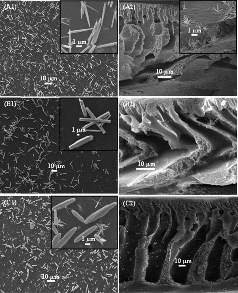
where n = 2 or 4, Zn2O(OH)2n−2 is the source of the heterogeneous nucleation and growth of ZnO nanowires. As we know, an alkaline solution is essential for the formation of ZnO nanostructures because normally divalent metal ions do not hydrolyze in acidic environments. The pH value of the growth solution is much lower than the isoelectric point (IEP) of ZnO (∼7.4),53 implying that ZnO crystals about 5–6 nm in size are positively charged and have a higher solubility in water compared to that of bulk ZnO.54 HMTA and NH3·H2O provide the NH3 (NH4+) and OH–, whereby the NH3 forms zinc amino complex [Zn(NH3)4]2+, thus leading to the consumption of Zn2+ in the growth solution to eventually lead to the growth of ZnO nanorods.48 The OH– ions obtained from the decomposition of methenamine lead to the erosion of zinc ions from the crystallites. The polar (0001) plane of the ZnO crystal seeds dissolve more quickly than the other six symmetric nonpolar planes during the growth process, as the polar face has a higher surface energy/atomic density (and is thus more unstable) than that of the other faces.45 On the other hand, these dissolved Zn2+ from the nanocrystals lead to local supersaturation, favoring the growth of nanorods. The growth units of [Zn(OH)4]2– can thus be adsorbed on the circumference of ZnO nuclei, whose surface energy (crystal) would decrease, thus resulting in the generation of multiple active sites on the surface. The diameter and the length of the formed rods depend on the availability of Zn2+ ions, the precursor pH, the temperature, and the growth time.48,53 During this process of dissolution and growth, the nanoparticles that blocked the pores of the membranes are dissolved, as they are used as active site for the growth of the nanorods, leading to a higher surface area of the membranes compared to that of the membranes blended with ZnO nanoparticles only. The growth of zinc oxide nanorods on the surface and through the thickness of the membrane is governed by the amount of ZnO nanoparticles in the membranes, which form the nuclei for the nanorod growth process. ZnO nanorods were found to grow longer and thicker in the membranes fabricated with increasing amounts of nanoparticles incorporated in the polymeric matrix (Figure 3). By increasing the ZnO content in the PES membrane to 6% and upon subsequent growth of the nanorods, two growth mechanisms can be observed (Figure 3). The primary growth, which gives thin ZnO nanorods and bigger particles forms due to the Ostwald ripening, and also a secondary growth take place simultaneously.55 ZnO nanorods were found to grow unevenly on the membrane surface as can also be observed from the SEM images shown in Figure 3.
Figure 3.
SEM images of the PES membranes incorporated with ZnO nanoparticles after ZnO nanorods growth. (A1) PES–ZnO-1 surface view and (A2) cross section, (B1) PES–ZnO-2 surface view and (B2) cross section, and (C1) PES–ZnO-3 surface view and (C2) cross section.
The attenuated total reflection (ATR)–FTIR spectra of the PES membranes and ZnO nanoparticles-modified PES membranes are shown in Figure S2. All of the spectra show characteristic PES patterns with no noticeable additional peaks observed upon the addition of ZnO nanoparticles. The PES structure corresponding peaks appear at 1582 cm–1 for (C=C) aromatic benzene rings. The peak at 1490 cm–1 corresponds to the C–C band of the aromatic ring. Sulfone group (S=O) appears at 1246 cm–1 and the aromatic ether (C–O–C) C–O band stretch appears at 1108 cm–1. Thus, it can be reasonably concluded that the inclusion of ZnO nanoparticles does not affect the molecular integrity of the PES membranes.
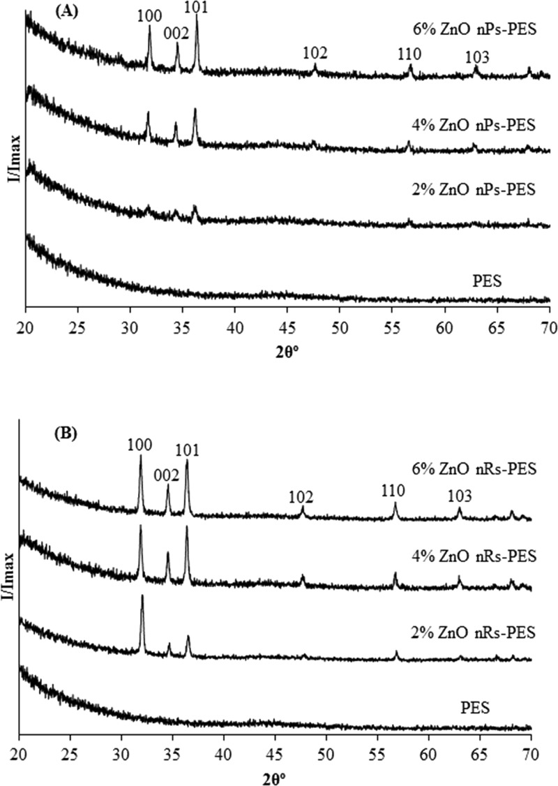
The XRD spectra (Figure 4) of the composite membranes confirm the inclusion of ZnO nanoparticles and the growth of nanorods, as ZnO peaks were found to be more pronounced in the samples with increasing content of the nanoparticles. The main diffraction due to ZnO crystals occurs at 31.85, 34.53, 36.35, 56.68, and 62.88°. A comparison of the relative intensities of planes (100), (002), and (101) showed that the relative intensities of the peaks (002) and (101) increased with increase in ZnO content. This indicates a nonpreferential growth of ZnO nanorods in the membranes.
Figure 4.
XRD patterns of (A) PES–ZnO nanoparticles and (B) PES–ZnO nanorods membranes.
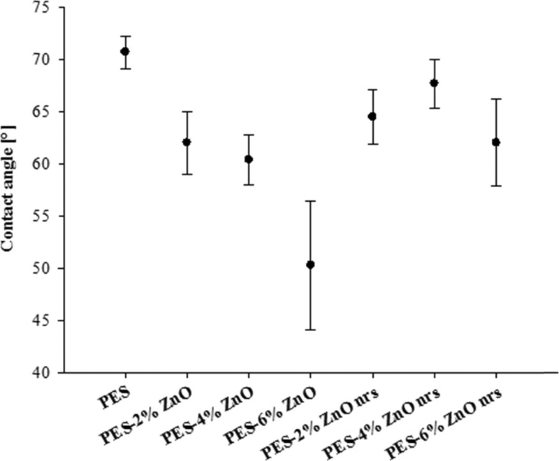
The growth orientation and the surface coverage of the ZnO nanorods play a significant role in the surface wetting characteristics, as has been shown by Myint et al.56 It is expected that optimization of the growth time of the nanorods will affect the density and the orientation of the rods; therefore, the surface properties can be controlled. The membrane surface hydrophilicity was evaluated by measuring the water contact angle in Figure 5. The contact angle of pure PES membrane was 70.65 ± 1.55°, which is considered as moderately hydrophilic, whereas the contact angle of the composite membrane decreased with increasing content of ZnO nanoparticles, which indicates an increase in the surface hydrophilicity. The effect of ZnO nanoparticles inclusion in PES was reported by other researchers, who used ZnO nanoparticles in the range of 0.5–2% and reported enhanced water flux through the membranes.3,26,33,35,43 After the growth of ZnO nanorods, the hydrophilicity of the PES–ZnO membranes was found to increase slightly compared to that of pristine PES. It is well known that the hydrophilicity of ZnO nanorod-coated surfaces is dependent on the nanorod size and growth orientations.57
Figure 5.
Water contact angle of the PES and PES–ZnO membranes measured at 25 °C.
Another surface property that affects the membrane performance is surface charge, which is a measure of the zeta potential and the IEP of the membranes. The titration curves in Figure S3 show the zeta potential of the PES and ZnO-NPs-modified PES membranes from pH ∼ 7 to pH 3, and the IEPs are summarized in Table 1. The IEP of pure PES is at pH 3.48, which was less acidic for the membranes blended with ZnO nanoparticles ranging from pH 3.85 to 4.14 and pH 3.84 to 4.02 on the membrane fabricated after growing the nanorods.
Table 1. Isoelectric Point of the PES Membrane and the ZnO-NPs-Modified PES Membranes.
| membrane | IEP |
|---|---|
| PES | pH 3.48 |
| PES–2% ZnO-NPs | pH 3.98 |
| PES–4% ZnO NPs | pH 4.14 |
| PES–6% ZnO NPs | pH 3.85 |
| PES–ZnO-01-NRs | pH 4.02 |
| PES–ZnO-02-NRs | pH 3.91 |
| PES–ZnO-03-NRs | pH 3.84 |
2.2. Water Flux and Bovine Serum Albumin (BSA) Removal
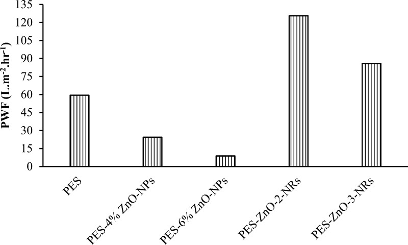
The pure water flux through the PES membrane and the ZnO-modified PES membranes measured at 10 bar pressure and monitored over 90 min is shown in Figure 6. The water flux for the pristine PES membranes was found to be 59.4 L m–2 h–1. Inspite of increased hydrophilicity of the membranes with the inclusion of ZnO nanoparticles, there was a decline in the water flux as ZnO content increased in the composite membranes. The lowest flux was observed to be 8.85 L m–2 h–1 for the membrane blended with 6% ZnO nanoparticles. This decline in the flux occurred due to the pore blockage upon blending the membranes with ZnO nanoparticles. However, upon growing ZnO nanorods on the membranes, the water permeation was found to be higher than the permeation through the membranes blended with ZnO nanoparticles alone. The higher surface area of the nanorods and native hydrophilicity of ZnO played a role in enhancing the water permeation through the membranes. The highest water flux of 125.6 L m–2 h–1 was achieved by blending the PES membranes with 4% ZnO nanoparticles and then growing ZnO nanorods.
Figure 6.
Pure water flux of the membranes measured at 10 bar.
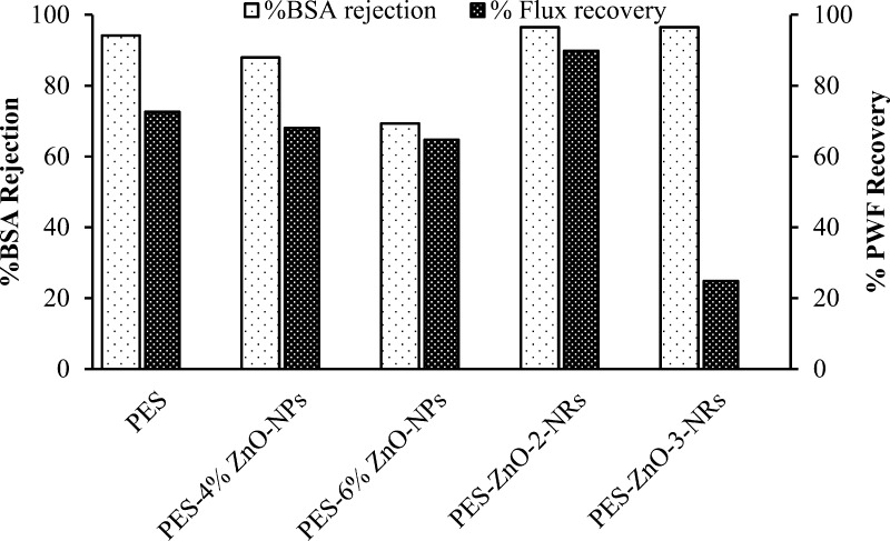
The membranes blended with ZnO nanoparticles and further modified by growing the nanorods were found to have a high BSA rejection and high water flux recovery after the BSA separation (Figure 7), compared to those of pristine PES and the PES membranes blended with ZnO nanoparticles. The BSA (96.53%) was removed using both the PES membrane blended with 4 and 6% ZnO and further modified by growing ZnO nanorods. However, the flux recovery was higher for the former membrane.
Figure 7.
BSA rejection and pure water flux recovery after BSA filtration measure at 10 bar for the PES and ZnO-modified membranes.
2.3. Antibacterial Activity
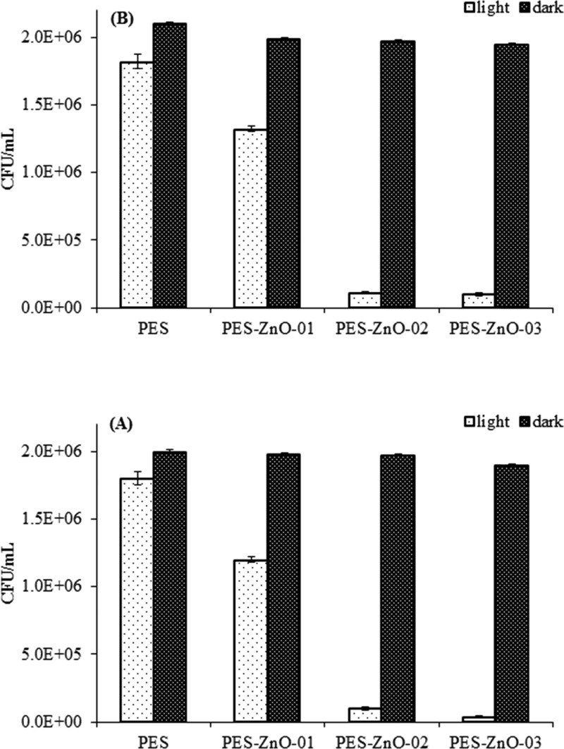
In the presence of the PES membranes modified with zinc oxide nanoparticles growth and in situ growth of nanorods under visible light irradiation, the number of colony-forming units (CFUs) of E. coli was significantly lower compared to that observed on the unmodified PES membrane (Figure 8) (ANOVA: p < 0.0001). On the other hand, the number of CFUs remained relatively unchanged for all of the samples kept under dark conditions. In case of both nanoparticles and nanorods, the antibacterial activity was found to increase with an increase in the zinc oxide content in the membranes (Figure 8). The highest reduction in the number of E. coli CFUs were observed in the membranes with 6% nanoparticles inclusion which were successively modified with ZnO nanorods. From our experimental results, the PES membrane embedded with nanorods has a significantly higher antibacterial activity (ANOVA, HSD, p < 0.05) compared to that of membranes fabricated solely with embedded nanoparticles. The absorbance measurements also support the observations made from the bacterial counting experiments.
Figure 8.
Effect of ZnO NPs (A) and ZnO NRs (B) in light (1060 W m–2) or dark conditions on CFUs (viable cells) for E. coli presented as mean ± SD of three replicates.
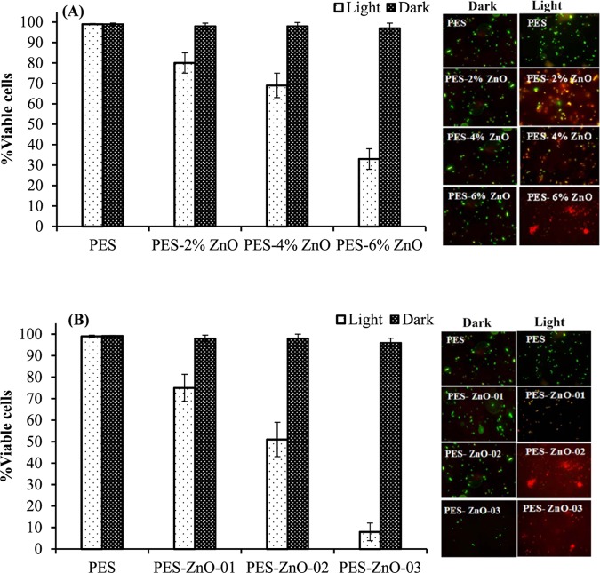
The CFU counting experiments are based on the growth of bacteria on agar.58 To confirm these measurements of the experiment, the number of viable bacteria was estimated by an epifloroscence microscopy through the staining of live and dead bacterial cells with SYBR green and propidium iodide dyes.59 The percentage of viable cells was found to be significantly reduced (ANOVA: p < 0.0001) in the presence of PES membranes with variable concentrations of embedded ZnO nanoparticles and nanorods compared to that of unmodified PES membrane in the presence of light (Figure 9). The number of viable bacterial cells remained relatively similar for all of the samples under dark conditions. The highest bacterial inactivation was achieved using the PES membranes embedded with 6% ZnO nanorods (Figure 11). An overall reduction in the number of cells was also observed after the photocatalytic treatment with PES membranes embedded with zinc oxide nanoparticles and nanorods.
Figure 9.
Effect of ZnO NPs (A) and ZnO NRs (B) in light (1060 W m–2) or dark conditions (no irradiation) on viability of E. coli bacterium after 5 h of photocatalysis. Data are presented as the mean ± SD of three replicates. Viable cell percentage (number of viable cells over total number of cells in %) is determined by live/dead staining. Subset in the figure shows representative stained micrograph for each sample.
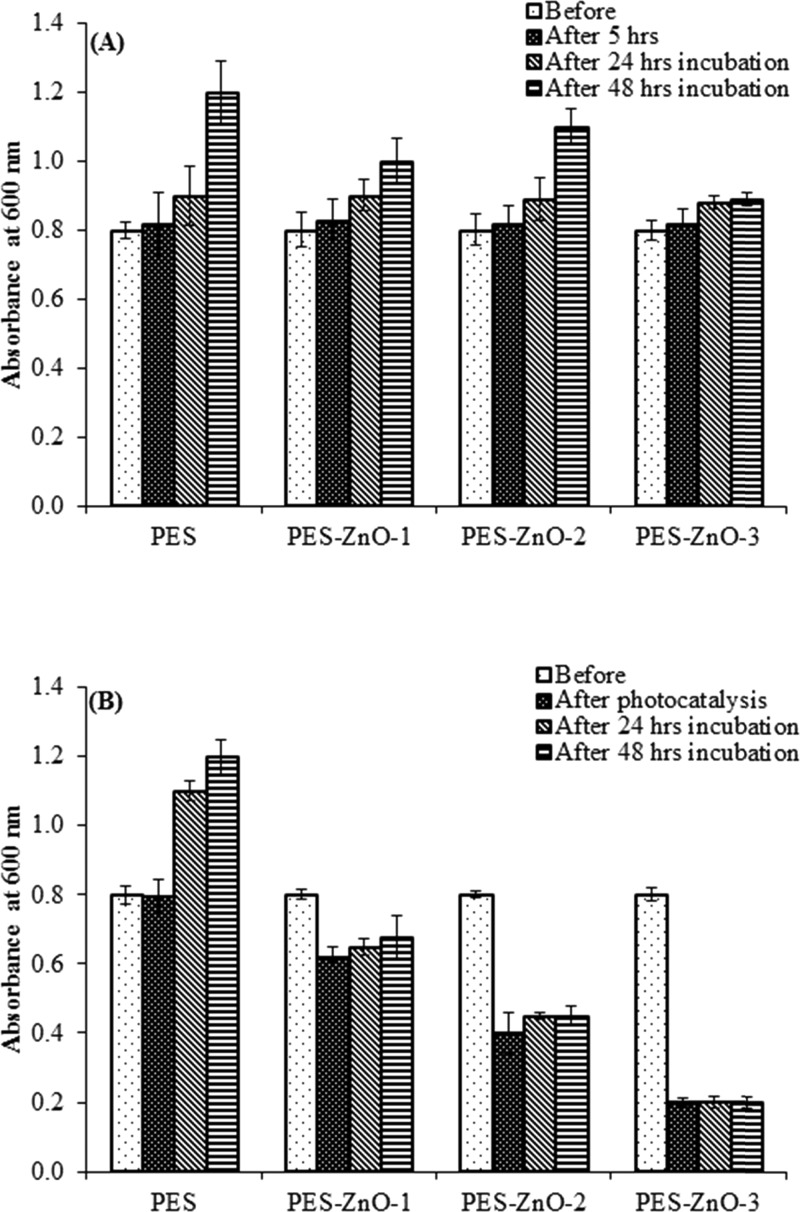
Figure 11.
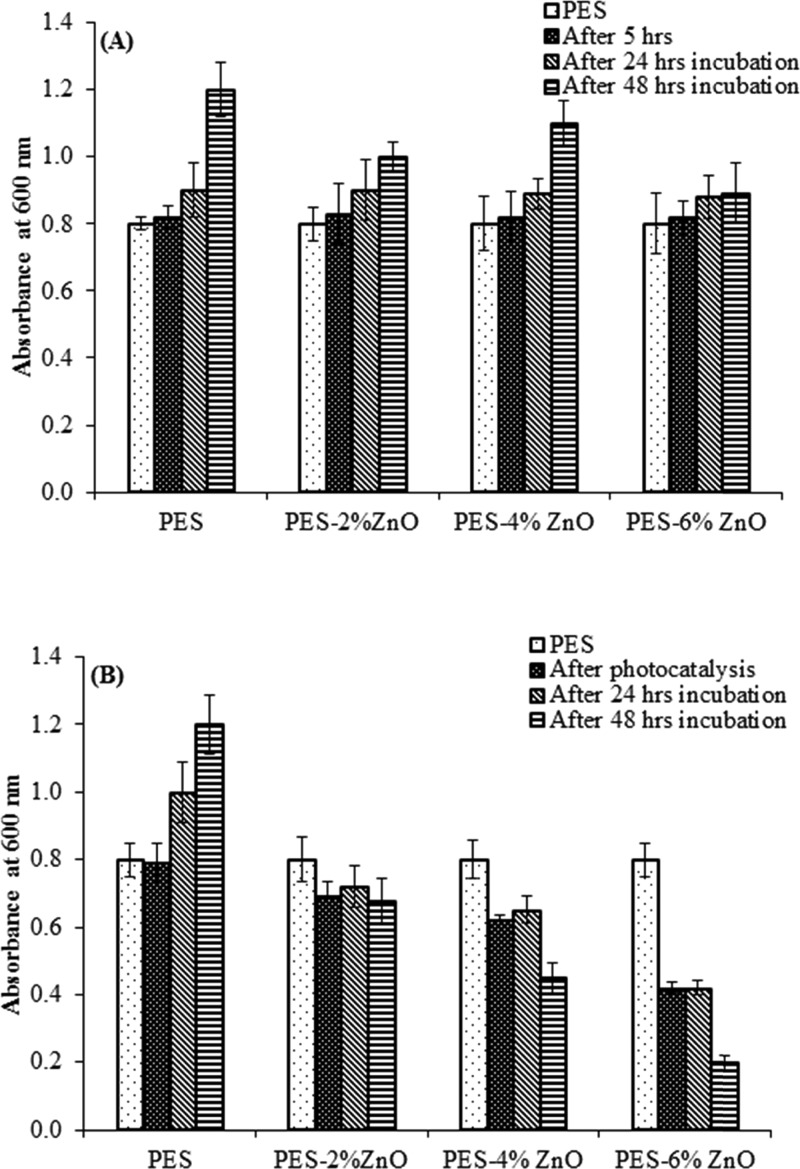
Effect of ZnO NRs (A) in light (0 W m–2) and (B) in dark (1060 W m–2) on regrowth of E. coli bacterium before photocatalysis, after photocatalysis, and after 24 h and after 48 h incubation.
Upon the excitation of zinc oxide with light above the band gap and in the presence of O2 and water, highly reactive oxygen species (ROS) are produced, which leads to the formation of O2–, OH•, and other oxygenated radical species.60 In photon-activated catalysis, the photocatalytic activity depends on the ability of the catalyst to create electron–hole pairs, which generate free radicals (hydroxyl radicals: •OH) that are capable of undergoing secondary reactions that can lead to microbial mortality as explained recently by Sathe et al.61 The photogenerated electrons at the conduction band reduce the adsorbed oxygen (O2) or organics producing a super oxide anion (O2–), which can react with the hydrogen ion (H+) to produce HO2*, subsequently forming water molecules. The photogenerated hole at the valence band can react with the adsorbed species according to following possible processes. For example, a hole can directly react with an organic molecule and oxidize it as follows62
| 6 |
It can also oxidize hydroxyl radical ion to hydroxyl radical
| 7 |
Also, it can oxidize water to give hydrogen ion and hydroxyl radical
| 8 |
2.4. Bacterial Regrowth
Similar to the antibacterial studies discussed in the last section, we observed that under light irradiation (in the presence of PES membranes modified with both ZnO nanoparticles and nanorods), there was a significant reduction in bacterial abundance (expressed as culture absorbance) compared to the control (ANOVA: p < 0.0001, Figures 10 and 11). Maximum reduction in absorbance was observed for the PES membrane modified with 6% ZnO nanoparticles and nanorods (Figures 10 and 11). Overall, a higher reduction in absorbance was observed with the PES membrane embedded with ZnO nanorods compared to that of the PES membranes embedded with nanoparticles. There was no effect of nanorods and nanoparticles under dark conditions. No bacterial regrowth was found in the presence of PES membranes modified with both ZnO nanoparticles and nanorods at all concentrations under light irradiation after 24 and 48 h incubation. These results suggest that most of the bacteria treated with the membranes were killed and the observed antibacterial activity is permanent.
Figure 10.
Effect of ZnO NPs (A) in dark (0 W m–2) and (B) in light (1060 W m–2) on regrowth of E. coli bacterium before photocatalysis, after photocatalysis, and after 24 h and after 48 h incubation.
In the control samples kept in dark (no light exposure during the experiment), bacterial growth was observed with increased absorbance over 24 and 48 h. Thus, the antibacterial activity of the PES membranes modified with both ZnO NP and ZnO NR only occurs upon irradiation with light, leading to the photocatalytic inhibition of the bacterial growth.63
2.5. Mechanism of Action
Former studies have demonstrated that ZnO nanoparticles possess strong antimicrobial activities against common pathogens such as S. aureus, S. epidermis, and E. coli.36,64 Zinc oxide nanorods were also shown to possess broad-spectrum antibacterial activity against Gram-positive (Staphylococcus aureus, Bacillus subtilis) and Gram-negative (E. coli, P. aeruginosa) bacteria and marine microalga Dunaliella salina in the presence of light.63,65 Our recent report showed the antifouling activity of zinc oxide nanorods supported on glass substrates.61 The proposed antibacterial properties of zinc oxide nanostructures include two possible mechanisms of action: (1) the production of ROS, mostly hydroxyl radicals and singlet oxygen, and (2) the toxicity of Zn2+ ions released from the nanocomposite substrate.66,67 Our current and previous investigations61,68 clearly demonstrated that the antifouling activity of ZnO nanorods is mainly due to the production of ROS. The produced ROS causes oxidation of the membrane lipids, resulting in membrane damage, leading to cell lysis.69 Our experiments showed better performance of zinc oxide nanorods over zinc oxide nanoparticles embedded within the PES matrix. This is probably due to the higher surface area of zinc oxide nanorods over nanoparticles. According to several reports, the generation of ROS, which are responsible for the antimicrobial activity, usually depends on the available surface area of ZnO nanostructures. A higher surface area accounts for a higher ROS production.29,64
3. Conclusions
The PES membranes blended with ZnO nanoparticles were fabricated by the phase inversion method and then used for the in situ growth of ZnO nanorods hydrothermally to improve the antibacterial activity of the membranes. The membranes have a asymmetric pore structure consisting of a top dense pore layer with fingerlike micropores. Surface properties of the membranes were altered by controlling ZnO content and growth conditions. The growth orientation was dependent on the amount and disparity of ZnO nanoparticles. The contact angle of the ZnO-blended membranes was reduced compared to that of the pristine PES membrane, indicating a higher hydrophilicity. Increasing the loading of ZnO nanoparticles up to 6% leads to nanoparticles aggregation and pore blockage, which reduces the water permeation by 15% compared to that of the pristine PES membrane. By in situ growth of ZnO nanorods, the surface area of the membranes was increased and the water flux was improved. The BSA removal was improved by growing the nanorods, and the flux was recovered up to 89.8% using the PES membrane blended with 4% ZnO and further modified by growing ZnO nanorods. Under the condition of light irradiation, E. coli growth was inhibited in the presence of the PES membranes modified by the incorporation of ZnO nanoparticles and the growth of ZnO nanorods. The inhibition was enhanced by increasing ZnO content due to the enhancement in the formation of the ROS, which attack the bacteria. No bacterial regrowth was observed after 48 h of incubation, indicating that the ROS kill most of the bacteria in the presence ZnO nanoparticles and nanorods. The highest bacterial growth reduction was 90%, which was achieved in the presence of the PES membrane incorporated with 6% ZnO nanoparticles and further modified by the growth of ZnO nanorods.
4. Experimental Section
4.1. Materials
The PES granules (Mw 58 000 g/mol) were purchased from Goodfellow Cambridge Limited (England). 1-Methyl-2-pyrrolidone (NMP) (Fluka analytical, Germany) was used as the solvent to dissolve PES. Zinc oxide nanoparticles (10–30 nm) were supplied by U.S. Research Nanomaterials, Inc.
Zinc nitrate hexahydrate (M.W. 297.49 g/mol, 99.05%) (Sigma-Aldrich) and hexamethylenetetramine (M.W 140.19 g/mol, 99.0%) (Merck) were used to prepare the precursor solutions for the growth of ZnO nanorods.
Epoxy (No. 20-8130-128) and Epoxy Hardener (No. 20-8132-032) (Buehler) were used for SEM sample preparation. Acetone and deionized water were used for cleaning purposes.
4.2. Fabrication of PES–ZnO NPs Membranes
Zinc oxide-blended PES membrane was fabricated by phase inversion and polymerization in deionized water.2,70−72 First, zinc oxide nanoparticles (10–30 nm) were dispersed in NMP by probe sonication for 30 min followed by magnetic stirring for 24 h. PES was added slowly and the mixture stirred for over 24 h to form a homogenous admixture. The quantities of the reagents used in these experiments and the viscosity of the nanoparticles containing the polymer solution are shown in Table 2. The viscosity was determined using a plate-to-plate method (Bohin Genmini Rotonetic drive 2 Rheometer, U.K.). The shear rates were measured with 2 mL samples at 25 °C from 0.1 to 100 s–1 in 5 min.
Table 2. Quantities of the Polymer and Zinc Oxide Nanoparticles Used to Cast the Membranes.
| membrane code | % additive | mass additive (g) | % PES | mass PES (g) | volume N-methyl-2-pyrrolidone (NMP) (mL) | viscosity (cP) |
|---|---|---|---|---|---|---|
| PES–NMP-01 | 0 | 0.00 | 15 | 30.00 | 165 | 271.3 |
| PES–ZnO-01 | 2 | 0.60 | 15 | 30.00 | 164.4 | 571.8 |
| PES–ZnO-02 | 4 | 1.20 | 15 | 30.00 | 163 | 728.1 |
| PES–ZnO-03 | 6 | 1.80 | 15 | 30.00 | 163 |
The membranes were cast on a (20 × 20 cm2) flat glass plate, and the casting thickness was adjusted by sticking tapes at the edges of the plate.26,71 A line of the solution was poured at one edge of the plate and then drawn with a steel tool to make a film of about 240 μm thickness. The membrane was then placed in a water bath at room temperature overnight and then washed repeatedly with deionized water followed by first drying in air for 2 days and then in a vacuum oven at 20 °C for 12 h.
4.3. Zinc Oxide Nanorods Hydrothermal Growth
The growth solution was prepared by mixing equimolar (20 mM) concentration of zinc nitrate with hexamethylenetetramine solution.49 The membranes were then immersed in the growth solution for 5 h and kept in an oven preheated to 90 °C. After 5 h, the membranes were removed from the growth solution, washed several times with deionized water, and dried at room temperature overnight followed by additional drying in a vacuum oven at room temperature at (25 °C) for 15 h.
4.4. Membrane Characterization
The images of membrane surface and the cross-sectional morphology were captured using JSM-7600F Field Emission Scanning Electron Microscope, from JEOL (Japan). The microscope was evacuated to 4 × 10⁻⁴ Pa and operated at 15 kV and 8 mA. The membrane surface was analyzed by mounting a piece of the membrane on an adhesive carbon film stuck to an aluminum sample holder to avoid charging. To obtain clear SEM micrographs, the membrane samples on the aluminum stub were further coated with a thin film of platinum using JFC-1600 Auto Fine Coater, from JEOL.
To scan the cross section of the membrane, a small piece of the sample was cut and fractured with liquid nitrogen or sliced using microtome equipped with a glass knife to cut thin sections of 500 nm thickness. Prior to slicing, the membrane was embedded in the epoxy to make a hard block.
The functional groups in the membrane’s chemical structure were analyzed by ATR infrared spectroscopy from PerkinElmer (SpectraOne) in the 4000–400 cm–1 range.
The membrane’s hydrophilicity/hydrophobicity was determined by measuring the static contact angle of the water drop on the membrane with Theta Lite attention tensiometer (Biolin Scientific, Sweden) using the sessile drop technique. A membrane film sample of 2 cm × 4 cm size was mounted on a glass slide supported with a double layer tape, and 5 μL of deionized water was placed on the surface of the membrane using a Hamilton syringe. Three measurements were made on each sample for left and right contact angles and then the average values were recorded.
The zeta potential of the membranes was measured using SurPASS Electrokinetic Analyzer from Anton Paar. A 0.001 M KCl(aq) solution was used as the electrolyte, and the pH was set at 6.64. The electrolytic solution was pumped through the cell, consisting of two membranes (2 cm × 1 cm) placed 100 μm apart. The streaming current method was chosen, and the zeta potential of the membranes at pH 6–7 was measured three times and then averaged. To obtain the IEP, a titration step was used for the pH range (7–3).
4.5. Pure Water Flux and BSA Rejection
The pure water flux and the BSA flux were measured using an ISCO Syringe pump (model 500D) coupled with an accumulator and a membrane support. First, the membrane was compacted at 10 bar for 90 min and then the water flux was measured at 10 bar. The flux was determined following eq 9
| 9 |
where J is the flux (L m–2 h–1), V is the volume of the collected permeate (L) at the period of time Δt (h), and A is the effective area of the membrane (m2).
After pure water flux measurements, the BSA was filtered through the membrane, which was then rinsed with deionized water, followed by pure water flux analysis to measure the flux recovery after the BSA filtration. The BSA rejection (eq 2) and the pure water flux recovery (eq 3) were calculated using the following equations
| 10 |
| 11 |
Cp and Cf are the BSA concentrations in the permeate and the feed, respectively, JR is the recovered water flux after the BSA filtration, and J0 is the initial water flux. The BSA concentration was obtained from the absorbance measurements using SHIMADZU UV–visible spectrophotometer (model UV-1650PC).
4.6. Antibacterial Activity of PES Membranes
4.6.1. Bacterial Culture and Photocatalysis
The effect of ZnO nanoparticle concentration on the Gram-negative bacterium Escherichia coli (ATCC 25922) was studied under visible light irradiation. The bacteria were cultured in Luria Bertani broth (Difco, Bergen County, NJ) (media pH 7.5) at 37 °C for 12 h. The bacterial cells were centrifuged at 5000 g at 25 °C for 10 min and resuspended in sterile deionized water. The 24-well plates (Costar, Tewksbury, MA) were used to carry out the photocatalysis experiments. Membrane samples of dimensions (0.5 cm × 0.5 cm) were cut and placed at the bottom of the 24-well plates. Each of the 24-well plates containing membranes (with ZnO nanoparticles or nanorods) or control samples (pure PES) was filled with 1.5 mL of the bacterial culture. Two similar sets of plates were prepared, one of which was exposed to visible light (∼AM 1.5G irradiation, ∼1060 and 530 W m–2), whereas the second set was covered with an aluminum foil and used as a dark control (0 W m–2). Each experiment was conducted for 5 h at 35 °C. All of the experiments were carried out three times. After 5 h, the bacterial density and conditions were determined to study the growth and viability.
4.6.2. Absorbance Measurement
At the end of the antibacterial experiments, 100 μL of the broth culture from each well (both under light and dark conditions) were collected and the absorbance was measured at 620 nm using a plate reader (Thermo Scientific). Three readings were taken, and the mean value was reported.
4.6.3. CFU Estimation
The CFU counting experiments were based on the growth of bacteria on agar.58 To confirm these measurements of the experiment, the number of viable bacteria was estimated by an epifloroscence microscope through the staining of live and dead bacterial cells with SYBR green and propidium iodide dyes.59 At the end of the antibacterial experiments, 1 mL of the broth culture from each well (both under light and dark conditions) was collected and diluted 50 times with sterile deionized water to determine the number of CFUs. A 0.1 mL from each diluted sample was plated on a petridish containing sterile nutrient agar (Difco). The plates were incubated at 37 °C for 24 h to allow microbial growth. Colonies were counted manually after 24 h. The CFU/mL was calculated using the following formula:
| 12 |
4.6.4. Variability Staining
At the end of the antibacterial experiments, 100 μL of the broth culture from each well (either after exposure to visible light or kept in dark conditions) was collected and utilized immediately for live and dead cell staining to estimate the number of dead cells. The live and dead cell staining of the samples was performed as per manufacturer’s instructions using live/dead Baclight bacterial viability kit (Life Technologies, Thermo Fisher). Ten microliters of the stained cell suspension was placed on a microscope slide. The number of live and dead bacteria in 20 randomly selected fields of view (area = 0.001 mm2) was counted using an epifloroscence microscope (Carl Zeiss, Germany; magnification 1000×). This method uses a mixture of SYTO 9 and propidium iodide dyes in dimethyl sulfoxide. SYTO 9 specifically stains cells with undamaged membranes, whereas the PI stains the cells with damaged membranes, enabling the quantification of live and dead cells in the samples.
4.6.5. Bacterial Regrowth Study after Photocatalytic Treatment
The bacterial cell suspensions treated with each type of membrane from 24-well plates were collected before and after 5 h of visible light irradiation using AM 1.5G irradiation with the incident power of 1 kW m–2 from a solar simulator (SS1.6 kW from Sciencetech, Canada) fitted with an IR filter. Bacterial regrowth was then monitored in the treated water sample for up to 48 h. The collected bacterial suspensions were then transferred to a 96-well plate (Costar, Tewksbury, MA) and maintained at 37 °C as described in Section 4.6.1. The bacterial regrowth was tested by accessing the increase in the bacterial biomass after 5, 24, and 48 h of light irradiation by absorbance spectroscopy following the 620 nm peak using a plate reader (Thermo Scientific). Three readings were taken, and the mean value was calculated.
4.6.6. Staining Analysis
Using Statistica 11 (Statsoft), the assumption of normality of the data was verified using the Shapiro–Wilk’s W-test. Factorial ANOVA was used to test the effect of photocatalytic treatment with nanocomposite membranes on the total bacterial density and the densities of live and dead bacteria. Tukey HSD post hoc test was used to test the significance of differences between densities of total live and dead bacteria. In all of the cases, the probability of error was 5% and the p value < 0.05 was considered statistically significant.
Acknowledgments
This work was supported by The Research Council under the project “Chair in Nanotechnology for Water Desalination, CHAIR/DVC/TRC/12/01.” The authors acknowledge the Central Analytical and Applied Research Unit (CAARU) at the College of Science and the Electron Microscope Unit at the College of Medicine for their help with the SEM images. The authors express gratitude to Prof. Rashid Al-Mamari, Professor, Department of Petroleum and Chemical Engineering, and his team for sharing the syringe pump to measure water permeation.
Supporting Information Available
The Supporting Information is available free of charge on the ACS Publications website at DOI: 10.1021/acsomega.7b00314.
Viscosity data of PES–ZnO mixtures (Table S1 and Figure S1), FTIR of PES–ZnO membranes (Figure S2), zeta potential titration curves (Figure S3), and E. coli absorbance in the presence of different PES–ZnO membranes (Figure S4) (PDF)
Author Contributions
The manuscript was written through contributions of all of the authors, who approved the final version of the manuscript. The contribution of the authors is as follows: Muna H. Al-Hinai, Mohammed Z. Al-Abri, Ashraf T. Al-Hinai, and Joydeep Dutta developed and designed the synthesis and the characterization experiments. Sergey Dobrestove helped in designing the antibacterial test experiments. Muna Al-Hinai prepared the membranes and characterized them. Priyanka Sathe carried out the antibacterial test and they contribute in manuscript writing. Mohammed Z. Al-Abri, Sergey Dobretsov, Ashraf T. Al-Hinai, and Joydeep Dutta supervised the work and the manuscript writing.
The authors declare no competing financial interest.
Supplementary Material
References
- Lee K. P.; Arnot T. C.; Mattia D. A review of reverse osmosis membrane materials for desalination—Development to date and future potential. J. Membr. Sci. 2011, 370, 1–22. 10.1016/j.memsci.2010.12.036. [DOI] [Google Scholar]
- Ani I.; Iqbal A.; NurdianaMohd N.. Asymmetric Polyether sulfone Membranes. In Membrane Technologies and Applications; CRC Press, 2011; pp 17–37. [Google Scholar]
- Rajabi H.; Ghaemi N.; Madaeni S. S.; Daraei P.; Astinchap B.; Zinadini S.; Razavizadeh S. H. Nano-ZnO embedded mixed matrix polyethersulfone (PES) membrane: Influence of nanofiller shape on characterization and fouling resistance. Appl. Surf. Sci. 2015, 349, 66–77. 10.1016/j.apsusc.2015.04.214. [DOI] [Google Scholar]
- Zhao C.; Xue J.; Ran F.; Sun S. Modification of polyethersulfone membranes – A review of methods. Prog. Mater. Sci. 2013, 58, 76–150. 10.1016/j.pmatsci.2012.07.002. [DOI] [Google Scholar]
- Wang J.; Gao X.; Wang Q.; Sun H.; Wang X.; Gao C. Enhanced biofouling resistance of polyethersulfone membrane surface modified with capsaicin derivative and itaconic acid. Appl. Surf. Sci. 2015, 356, 467–474. 10.1016/j.apsusc.2015.08.095. [DOI] [Google Scholar]
- Bojarska M.; Nowak B.; Skowroński J.; Piątkiewicz W.; Gradoń L. Growth of ZnO nanowires on polypropylene membrane surface—Characterization and reactivity. Appl. Surf. Sci. 2017, 391, 457–467. 10.1016/j.apsusc.2016.04.130. [DOI] [Google Scholar]
- Jamaly S.; Darwish N. N.; Ahmed I.; Hasan S. W. A short review on reverse osmosis pretreatment technologies. Desalination 2014, 354, 30–38. 10.1016/j.desal.2014.09.017. [DOI] [Google Scholar]
- Al-Juboori R. A.; Yusaf T. Biofouling in RO system: Mechanisms, monitoring and controlling. Desalination 2012, 302, 1–23. 10.1016/j.desal.2012.06.016. [DOI] [Google Scholar]
- Khan M. T.; Manes C.-L. d. O.; Aubry C.; Croué J.-P. Source water quality shaping different fouling scenarios in a full-scale desalination plant at the Red Sea. Water Res. 2013, 47, 558–568. 10.1016/j.watres.2012.10.017. [DOI] [PubMed] [Google Scholar]
- Van der Bruggen B. Chemical modification of polyethersulfone nanofiltration membranes: A review. J. Appl. Polym. Sci. 2009, 114, 630–642. 10.1002/app.30578. [DOI] [Google Scholar]
- Chong M. N.; Jin B.; Chow C. W. K.; Saint C. Recent developments in photocatalytic water treatment technology: A review. Water Res. 2010, 44, 2997–3027. 10.1016/j.watres.2010.02.039. [DOI] [PubMed] [Google Scholar]
- Le-Clech P.; Chen V.; Fane T. A. G. Fouling in membrane bioreactors used in wastewater treatment. J. Membr. Sci. 2006, 284, 17–53. 10.1016/j.memsci.2006.08.019. [DOI] [Google Scholar]
- Spring A. J.; Bagley D. M.; Andrews R. C.; Lemanik S.; Yang P. Removal of endocrine disrupting compounds using a membrane bioreactor and disinfection. J. Environ. Eng. Sci. 2007, 6, 131–137. 10.1139/s06-049. [DOI] [Google Scholar]
- Templeton M. R.; Oddy F.; Leung W.-k.; Rogers M. Chlorine and UV disinfection of ampicillin-resistant and trimethoprim-resistant Escherichia coli A paper submitted to the Journal of Environmental Engineering and Science. Can. J. Civ. Eng. 2009, 36, 889–894. 10.1139/L09-040. [DOI] [Google Scholar]
- Nguyen T.; Roddick F.; Fan L. Biofouling of Water Treatment Membranes: A Review of the Underlying Causes, Monitoring Techniques and Control Measures. Membranes 2012, 2, 804. 10.3390/membranes2040804. [DOI] [PMC free article] [PubMed] [Google Scholar]
- Li S.-S.; Xie Y.; Xiang T.; Ma L.; He C.; Sun S.-d.; Zhao C.-S. Heparin-mimicking polyethersulfone membranes – hemocompatibility, cytocompatibility, antifouling and antibacterial properties. J. Membr. Sci. 2016, 498, 135–146. 10.1016/j.memsci.2015.09.054. [DOI] [Google Scholar]
- Razali N. F.; Mohammad A. W.; Hilal N.; Leo C. P.; Alam J. Optimisation of polyethersulfone/polyaniline blended membranes using response surface methodology approach. Desalination 2013, 311, 182–191. 10.1016/j.desal.2012.11.033. [DOI] [Google Scholar]
- Shi Z.-Q.; Ji H.-F.; Yu H.-C.; Huang X.-L.; Zhao W.-F.; Sun S.-D.; Zhao C.-S. Engineering polyethersulfone hollow fiber membrane with improved blood compatibility and antibacterial property. Colloid Polym. Sci. 2016, 294, 441–453. 10.1007/s00396-015-3801-7. [DOI] [Google Scholar]
- Li F.; Meng J.; Ye J.; Yang B.; Tian Q.; Deng C. Surface modification of PES ultrafiltration membrane by polydopamine coating and poly(ethylene glycol) grafting: Morphology, stability, and anti-fouling. Desalination 2014, 344, 422–430. 10.1016/j.desal.2014.04.011. [DOI] [Google Scholar]
- Yu S.; Lü Z.; Chen Z.; Liu X.; Liu M.; Gao C. Surface modification of thin-film composite polyamide reverse osmosis membranes by coating N-isopropylacrylamide-co-acrylic acid copolymers for improved membrane properties. J. Membr. Sci. 2011, 371, 293–306. 10.1016/j.memsci.2011.01.059. [DOI] [Google Scholar]
- Song H.; Ran F.; Fan H.; Niu X.; Kang L.; Zhao C. Hemocompatibility and ultrafiltration performance of surface-functionalized polyethersulfone membrane by blending comb-like amphiphilic block copolymer. J. Membr. Sci. 2014, 471, 319–327. 10.1016/j.memsci.2014.08.013. [DOI] [Google Scholar]
- Razmjou A.; Mansouri J.; Chen V.; Lim M.; Amal R. Titania nanocomposite polyethersulfone ultrafiltration membranes fabricated using a low temperature hydrothermal coating process. J. Membr. Sci. 2011, 380, 98–113. 10.1016/j.memsci.2011.06.035. [DOI] [Google Scholar]
- Kausar A.; Hussain S. T. Effect of modified filler surfaces and filler-tethered polymer chains on morphology and physical properties of poly(azo-pyridyl-urethane)/multi-walled carbon nanotube nanocomposites. J. Plast. Film Sheeting 2014, 30, 181–204. 10.1177/8756087913493633. [DOI] [Google Scholar]
- Basri H.; Ismail A. F.; Aziz M.; Nagai K.; Matsuura T.; Abdullah M. S.; Ng B. C. Silver-filled polyethersulfone membranes for antibacterial applications — Effect of PVP and TAP addition on silver dispersion. Desalination 2010, 261, 264–271. 10.1016/j.desal.2010.05.009. [DOI] [Google Scholar]
- Huang J.; Zhang K.; Wang K.; Xie Z.; Ladewig B.; Wang H. Fabrication of polyethersulfone-mesoporous silica nanocomposite ultrafiltration membranes with antifouling properties. J. Membr. Sci. 2012, 423–424, 362–370. 10.1016/j.memsci.2012.08.029. [DOI] [Google Scholar]
- Zhao S.; Yan W.; Shi M.; Wang Z.; Wang J.; Wang S. Improving permeability and antifouling performance of polyethersulfone ultrafiltration membrane by incorporation of ZnO-DMF dispersion containing nano-ZnO and polyvinylpyrrolidone. J. Membr. Sci. 2015, 478, 105–116. 10.1016/j.memsci.2014.12.050. [DOI] [Google Scholar]
- Biswas P.; Bandyopadhyaya R. Biofouling prevention using silver nanoparticle impregnated polyethersulfone (PES) membrane: E. coli cell-killing in a continuous cross-flow membrane module. J. Colloid Interface Sci. 2017, 491, 13–26. 10.1016/j.jcis.2016.11.060. [DOI] [PubMed] [Google Scholar]
- Moghimifar V.; Raisi A.; Aroujalian A. Surface modification of polyethersulfone ultrafiltration membranes by corona plasma-assisted coating TiO2 nanoparticles. J. Membr. Sci. 2014, 461, 69–80. 10.1016/j.memsci.2014.02.012. [DOI] [Google Scholar]
- Nagarajan P.; Rajagopalan V. Enhanced bioactivity of ZnO nanoparticles—an antimicrobial study. Sci. Technol. Adv. Mater. 2008, 9, 035004 10.1088/1468-6996/9/3/035004. [DOI] [PMC free article] [PubMed] [Google Scholar]
- Yu L.; Zhang Y.; Zhang B.; Liu J.; Zhang H.; Song C. Preparation and characterization of HPEI-GO/PES ultrafiltration membrane with antifouling and antibacterial properties. J. Membr. Sci. 2013, 447, 452–462. 10.1016/j.memsci.2013.07.042. [DOI] [Google Scholar]
- Zhao Q.; Liu C.; Liu J.; Zhang Y. Development of a novel polyethersulfone ultrafiltration membrane with antibacterial activity and high flux containing halloysite nanotubes loaded with lysozyme. RSC Adv. 2015, 5, 38646–38653. 10.1039/C5RA05062F. [DOI] [Google Scholar]
- Kaner P.; Johnson D. J.; Seker E.; Hilal N.; Altinkaya S. A. Layer-by-layer surface modification of polyethersulfone membranes using polyelectrolytes and AgCl/TiO2 xerogels. J. Membr. Sci. 2015, 493, 807–819. 10.1016/j.memsci.2015.05.048. [DOI] [Google Scholar]
- Shen L.; Bian X.; Lu X.; Shi L.; Liu Z.; Chen L.; Hou Z.; Fan K. Preparation and characterization of ZnO/polyethersulfone (PES) hybrid membranes. Desalination 2012, 293, 21–29. 10.1016/j.desal.2012.02.019. [DOI] [Google Scholar]
- Chen Y.; Zhang Y.; Liu J.; Zhang H.; Wang K. Preparation and antibacterial property of polyethersulfone ultrafiltration hybrid membrane containing halloysite nanotubes loaded with copper ions. Chem. Eng. J. 2012, 210, 298–308. 10.1016/j.cej.2012.08.100. [DOI] [Google Scholar]
- Ahmad A. L.; Abdulkarim A. A.; Ismail S.; Ooi B. S. Preparation and characterisation of PES-ZnO mixed matrix membranes for humic acid removal. Desalin. Water Treat. 2015, 54, 3257–3268. 10.1080/19443994.2014.910137. [DOI] [Google Scholar]
- Zhang L.; Jiang Y.; Ding Y.; Povey M.; York D. Investigation into the antibacterial behaviour of suspensions of ZnO nanoparticles (ZnO nanofluids). J. Nanopart. Res. 2007, 9, 479–489. 10.1007/s11051-006-9150-1. [DOI] [Google Scholar]
- Leo C. P.; Cathie Lee W. P.; Ahmad A. L.; Mohammad A. W. Polysulfone membranes blended with ZnO nanoparticles for reducing fouling by oleic acid. Sep. Purif. Technol. 2012, 89, 51–56. 10.1016/j.seppur.2012.01.002. [DOI] [Google Scholar]
- Lee K. M.; Lai C. W.; Ngai K. S.; Juan J. C. Recent developments of zinc oxide based photocatalyst in water treatment technology: A review. Water Res. 2016, 88, 428–448. 10.1016/j.watres.2015.09.045. [DOI] [PubMed] [Google Scholar]
- Shibin O. M.; Yesodharan S.; Yesodharan E. P. Sunlight induced photocatalytic degradation of herbicide diquat in water in presence of ZnO. J. Environ. Chem. Eng. 2015, 3, 1107–1116. 10.1016/j.jece.2015.04.026. [DOI] [Google Scholar]
- Saikia L.; Bhuyan D.; Saikia M.; Malakar B.; Dutta D. K.; Sengupta P. Photocatalytic performance of ZnO nanomaterials for self sensitized degradation of malachite green dye under solar light. Appl. Catal., A 2015, 490, 42–49. 10.1016/j.apcata.2014.10.053. [DOI] [Google Scholar]
- He L.; Liu Y.; Mustapha A.; Lin M. Antifungal activity of zinc oxide nanoparticles against Botrytis cinerea and Penicillium expansum. Microbiol. Res. 2011, 166, 207–215. 10.1016/j.micres.2010.03.003. [DOI] [PubMed] [Google Scholar]
- Wong S. W. Y.; Leung P. T. Y.; Djurišić A. B.; Leung K. M. Y. Toxicities of nano zinc oxide to five marine organisms: influences of aggregate size and ion solubility. Anal. Bioanal. Chem. 2010, 396, 609–618. 10.1007/s00216-009-3249-z. [DOI] [PubMed] [Google Scholar]
- Balta S.; Sotto A.; Luis P.; Benea L.; Van der Bruggen B.; Kim J. A new outlook on membrane enhancement with nanoparticles: The alternative of ZnO. J. Membr. Sci. 2012, 389, 155–161. 10.1016/j.memsci.2011.10.025. [DOI] [Google Scholar]
- Huang J.; Zhang K.; Wang K.; Xie Z.; Ladewig B.; Wang H. Fabrication of polyethersulfone-mesoporous silica nanocomposite ultrafiltration membranes with antifouling properties. J. Membr. Sci. 2012, 423–424, 362–370. 10.1016/j.memsci.2012.08.029. [DOI] [Google Scholar]
- Baruah S.; Dutta J. Effect of seeded substrates on hydrothermally grown ZnO nanorods. J. Sol-Gel Sci. Technol. 2009, 50, 456. 10.1007/s10971-009-1917-2. [DOI] [Google Scholar]
- Sunandan B.; Joydeep D. Hydrothermal growth of ZnO nanostructures. Sci. Technol. Adv. Mater. 2009, 10, 013001 10.1088/1468-6996/10/1/013001. [DOI] [PMC free article] [PubMed] [Google Scholar]
- Ashfold M. N. R.; Doherty R. P.; Ndifor-Angwafor N. G.; Riley D. J.; Sun Y. The kinetics of the hydrothermal growth of ZnO nanostructures. Thin Solid Films 2007, 515, 8679–8683. 10.1016/j.tsf.2007.03.122. [DOI] [Google Scholar]
- Baruah S.; Dutta J. pH-dependent growth of zinc oxide nanorods. J. Cryst. Growth 2009, 311, 2549–2554. 10.1016/j.jcrysgro.2009.01.135. [DOI] [Google Scholar]
- Thuraya S. M. A. H.Supported ZnO Nanostructures: Synthesis, Kinetics and Application. M.Sc. Thesis, Sultan Qaboos University, 2013. [Google Scholar]
- Bian S.-W.; Mudunkotuwa I. A.; Rupasinghe T.; Grassian V. H. Aggregation and Dissolution of 4 nm ZnO Nanoparticles in Aqueous Environments: Influence of pH, Ionic Strength, Size, and Adsorption of Humic Acid. Langmuir 2011, 27, 6059–6068. 10.1021/la200570n. [DOI] [PubMed] [Google Scholar]
- Peterson R. B.; Fields C. L.; Gregg B. A. Epitaxial Chemical Deposition of ZnO Nanocolumns from NaOH Solutions. Langmuir 2004, 20, 5114–5118. 10.1021/la049683c. [DOI] [PubMed] [Google Scholar]
- Yamabi S.; Yahiro J.; Iwai S.; Imai H. Formation of cellular films consisting of wurtzite-type zinc oxide nanosheets by mediation of phosphate anions. Thin Solid Films 2005, 489, 23–30. 10.1016/j.tsf.2005.04.073. [DOI] [Google Scholar]
- Degen A.; Kosec M. Effect of pH and impurities on the surface charge of zinc oxide in aqueous solution. J. Eur. Ceram. Soc. 2000, 20, 667–673. 10.1016/S0955-2219(99)00203-4. [DOI] [Google Scholar]
- David C. A.; Galceran J.; Rey-Castro C.; Puy J.; Companys E.; Salvador J.; Monné J.; Wallace R.; Vakourov A. Dissolution Kinetics and Solubility of ZnO Nanoparticles Followed by AGNES. J. Phys. Chem. C 2012, 116, 11758–11767. 10.1021/jp301671b. [DOI] [Google Scholar]
- Baldan A. Review Progress in Ostwald ripening theories and their applications to nickel-base superalloys Part I: Ostwald ripening theories. J. Mater. Sci. 2002, 37, 2171–2202. 10.1023/A:1015388912729. [DOI] [Google Scholar]
- Myint M. T. Z.; Kitsomboonloha R.; Baruah S.; Dutta J. Superhydrophobic surfaces using selected zinc oxide microrod growth on ink-jetted patterns. J. Colloid Interface Sci. 2011, 354, 810–815. 10.1016/j.jcis.2010.11.004. [DOI] [PubMed] [Google Scholar]
- Myint M. T. Z.; Kumar N. S.; Hornyak G. L.; Dutta J. Hydrophobic/hydrophilic switching on zinc oxide micro-textured surface. Appl. Surf. Sci. 2013, 264, 344–348. 10.1016/j.apsusc.2012.10.024. [DOI] [Google Scholar]
- Oliver J. D. The viable but non-culturable state in the human pathogen Vibrio vulnificus. FEMS Microbiol. Lett. 1995, 133, 203–208. 10.1016/0378-1097(95)00329-4. [DOI] [PubMed] [Google Scholar]
- Nocker A.; Cheung C.-Y.; Camper A. K. Comparison of propidium monoazide with ethidium monoazide for differentiation of live vs. dead bacteria by selective removal of DNA from dead cells. J. Microbiol. Methods 2006, 67, 310–320. 10.1016/j.mimet.2006.04.015. [DOI] [PubMed] [Google Scholar]
- María Arsuaga J.; Sotto A.; del Rosario G.; Martínez A.; Molina S.; Teli S. B.; de Abajo J. Influence of the type, size, and distribution of metal oxide particles on the properties of nanocomposite ultrafiltration membranes. J. Membr. Sci. 2013, 428, 131–141. 10.1016/j.memsci.2012.11.008. [DOI] [Google Scholar]
- Sathe P.; Richter J.; Myint M. T. Z.; Dobretsov S.; Dutta J. Self-decontaminating photocatalytic zinc oxide nanorod coatings for prevention of marine microfouling: a mesocosm study. Biofouling 2016, 32, 383. 10.1080/08927014.2016.1146256. [DOI] [PubMed] [Google Scholar]
- Castellote M.; Bengtsson N.. Principles of TiO2 Photocatalysis. In Applications of Titanium Dioxide Photocatalysis to Construction Materials: State-of-the-Art Report of the RILEM Technical Committee 194-TDP; Ohama Y., Van Gemert D., Eds.; Springer: Dordrecht, Netherlands, 2011; pp 5–10.
- Sathe P.; Myint M. T. Z.; Dobretsov S.; Dutta J. Removal and regrowth inhibition of microalgae using visible light photocatalysis with ZnO nanorods: A green technology. Sep. Purif. Technol. 2016, 162, 61–67. 10.1016/j.seppur.2016.02.007. [DOI] [Google Scholar]
- Jones N.; Ray B.; Ranjit K. T.; Manna A. C. Antibacterial activity of ZnO nanoparticle suspensions on a broad spectrum of microorganisms. FEMS Microbiol. Lett. 2008, 279, 71–76. 10.1111/j.1574-6968.2007.01012.x. [DOI] [PubMed] [Google Scholar]
- Jansson T.; Clare-Salzler Z. J.; Zaveri T. D.; Mehta S.; Dolgova N. V.; Chu B.-H.; Ren F.; Keselowsky B. G. Antibacterial Effects of Zinc Oxide Nanorod Surfaces. J. Nanosci. Nanotechnol. 2012, 12, 7132–7138. 10.1166/jnn.2012.6587. [DOI] [PubMed] [Google Scholar]
- Han J.; Qiu W.; Gao W. Potential dissolution and photo-dissolution of ZnO thin films. J. Hazard. Mater. 2010, 178, 115–122. 10.1016/j.jhazmat.2010.01.050. [DOI] [PubMed] [Google Scholar]
- Li M.; Lin D.; Zhu L. Effects of water chemistry on the dissolution of ZnO nanoparticles and their toxicity to Escherichia coli. Environ. Pollut. 2013, 173, 97–102. 10.1016/j.envpol.2012.10.026. [DOI] [PubMed] [Google Scholar]
- Bora T.; Sathe P.; Laxman K.; Dobretsov S.; Dutta J. Defect engineered visible light active ZnO nanorods for photocatalytic treatment of water. Catal. Today 2017, 284, 11–18. 10.1016/j.cattod.2016.09.014. [DOI] [Google Scholar]
- Dutta R. K.; Nenavathu B. P.; Gangishetty M. K.; Reddy A. Studies on antibacterial activity of ZnO nanoparticles by ROS induced lipid peroxidation. Colloids Surf., B 2012, 94, 143–150. 10.1016/j.colsurfb.2012.01.046. [DOI] [PubMed] [Google Scholar]
- Barth C.; Gonçalves M. C.; Pires A. T. N.; Roeder J.; Wolf B. A. Asymmetric polysulfone and polyethersulfone membranes: effects of thermodynamic conditions during formation on their performance. J. Membr. Sci. 2000, 169, 287–299. 10.1016/S0376-7388(99)00344-0. [DOI] [Google Scholar]
- Chaturvedi B. K.; Ghosh A. K.; Ramachandhran V.; Trivedi M. K.; Hanra M. S.; Misra B. M. Preparation, characterization and performance of polyethersulfone ultrafiltration membranes. Desalination 2001, 133, 31–40. 10.1016/S0011-9164(01)00080-7. [DOI] [Google Scholar]
- Liu X.; Yu Y.; Li S. Viscoelastic phase separation in polyethersulfone modified bismaleimide resin. Eur. Polym. J. 2006, 42, 835–842. 10.1016/j.eurpolymj.2005.10.004. [DOI] [Google Scholar]
Associated Data
This section collects any data citations, data availability statements, or supplementary materials included in this article.


