Abstract
In this article, the silk fibroin (SF)/graphene oxide (GO)-blended nanofibers with one bioinspired nanostructure are fabricated via electrospinning. The morphology, chemical structure, antibacterial activity, and biocompatibility of the blending nanofibers are investigated. The results indicate that GO plays an important role in preparing the distinctive bioinspired structure. The antibacterial activity and in vivo cell culture test demonstrate that blending of GO could improve the antibacterial activity and biocompatibility of SF nanofibers. The blended nanofibers developed in this study may have considerable potential for wound dressing applications.
1. Introduction
Recently, electrospinning has been used widely to fabricate various biomedical materials because it can prepare nanofibers to mimic the extracellular matrix.1−4Bombyx mori silk extracted from the silkworm is called the empress of fibers due to its unique properties (mechanical and optical characteristics).5,6 Native Bombyx mori silk is composed of silk fibroin (SF) coated with silk sericin proteins. Because of favorable biocompatibility and a minimal inflammatory reaction,7 SF has been fabricated into a variety of silk-based materials, such as gel, fiber, powder, sponge, film, tube, and so on,8−13 and these silk-based materials have been widely used for tissue engineering scaffold.14−16
During the past 3 years, there have been many reports about electrospinning SF nanofibers, which are used for wound dressing.17,18 As we know, wound dressing materials have higher requirements for antimicrobial and biocompatible materials. However, the SF is known for lacking antibacterial property and the biocompatibility of SF needs further improvement. Therefore, in practical applications, SF is often modified by some functional nanomaterials.19−21 Graphene oxide (GO) contains a large number of functional groups and an extremely large surface-to-volume ratio, which gives some unique properties of GO, such as excellent hydrophilicity, dispersion, and biocompatibility. In addition to the above properties, GO has one unique antibacterial property. Because of the above excellent performance, GO has been widely used in biomedical materials.22−25
In this article, the SF/GO-blended nanofibers are fabricated by electrospinning. Macroscopic and microscopic morphologies of the blended nanofibers are prepared by scanning electron microscopy (SEM), transmission electron microscope (TEM), energy dispersive spectrometry, X-ray diffraction (XRD), X-ray photoelectron spectroscopy (XPS), and Raman spectra. In particular, the antibacterial property and biocompatibility are characterized by antibacterial experiment and cell culture. Furthermore, the mechanisms of improving the antibacterial mechanism and biocompatibility are analyzed. The testing results show that the blended nanofiber is an appropriate candidate for wound dressing.
2. Results and Discussion
2.1. Morphology and Microstructure of GO
The morphology of the GO sheets is characterized by TEM and atomic force microscopy (AFM) (Figure 1a,b), as shown in the TEM and AFM images; it shows GO’s typical lateral dimensions and a single-layer structure, with thickness of 0.8 nm.26 The microstructure of GO was studied by Raman and XPS; the results are shown in Figure 1c,d. It could be seen from Figure 1c that two characteristic peaks of 1340 and 1580 cm–1 are shown in the Raman spectrum, which could be assigned to the D-band and G-band of carbon, respectively.27 According to the result of XPS, we calculate the atomic ratio of C/O in the GO nanosheet is about 2.2. According to the peak fitting of the carbon element (Figure 1d), four types of carbon bonds are characterized, which are alkyl/olefin (284.6 eV), aldehyde (286.6 eV), carbonyl (287.7 eV), and carboxyl (289.0 eV), respectively. Because of these hydrophilic bonds, the GO can disperse well in water.28,29 The above results indicate that the GO sheets are prepared successfully.
Figure 1.
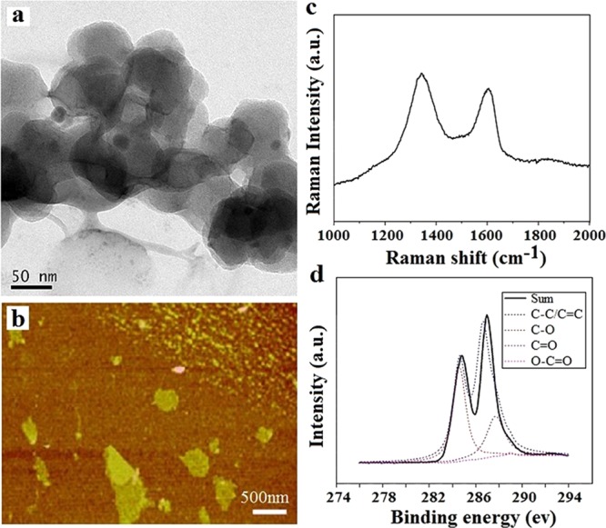
Characterizations of the GO. (a, b) SEM and AFM images, (c, d) Raman and XPS spectra.
2.2. Morphology of the Electrospinning SF/GO-Blended Nanofibers
Figure S1 shows the morphology of the as-spun and ethanol-treated pure SF and SF/GO-blended nanofibers with different blended ratios. It could be seen that the homogeneous and beads-free nanofibers could be obtained using pure SF solution. However, there are a number of spheres attached to the surface of the SF/GO-blended nanofibers and the quantity of the spheres increases with the increase of the GO concentration. To analyze this phenomenon, we chose the SF/GO-blended nanofibers with high concentration of GO as the research subject.
Figure 2a,b shows the SEM images of the pure SF and SF/GO-blended nanofibers (with GO concentration of 5 wt %). As shown in Figure 2a, homogeneous and beads-free nanofibers could be obtained using pure SF solution; the average diameter of the nanofibers is about 100 nm. It could be seen from Figure 2b that the SF/GO nanofibers can also be fabricated successfully by electrospinning. However, the diameter of the SF/GO-blended nanofibers decreases when compared to that of the pure SF; this is due to the addition of GO aqueous solution that decreases the viscosity of the spinning solution, which is shown in Figure S2. Moreover, it can be seen from Figure 2b that the surface has a number of spheres attached to the surface of the fiber in a beaded form. From Figure 2b, we cannot find the GO; it is concluded that the beads on the surface of the blended nanofibers are GO, which are packaged by SF on the surface. To verify the above hypothesis, the SF/GO-blended nanofibers are observed by TEM. Figure 2c shows a homogeneous distribution of the pure SF nanofibers, and it can also be seen from Figure 2d that there are a number of spheres on the surface of the SF/GO-blended nanofibers. Furthermore, as shown in the high resolution of the TEM image (Figure 2d), we can clearly see that the GO nanosheets are packaged inside the SF nanofibers. Therefore, it is concluded that the GO nanosheets are coated in the SF nanofibers with a globular form. Moreover, the dimension of the packaged GO nanosheets ranges from 50 to 1000 nm.
Figure 2.
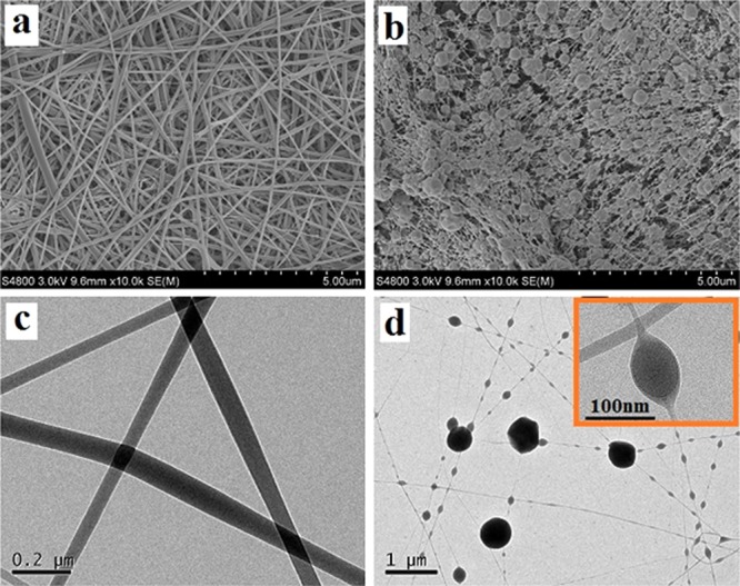
SEM images of the pure SF nanofibers (a) and SF/GO-blended nanofibers (b) and TEM images of the pure SF nanofibers (c) and SF/GO-blended nanofibers (d).
2.3. Chemical Structures the Electrospinning SF/GO-Blended Nanofibers
Figure 3 shows the Raman spectra of the pure SF and SF/GO-blended nanofibers. As shown in Figure 3, both the SF and SF/GO nanofibers do not show obvious SF characteristic peaks at 1660 and 1250 cm–1 (amide I and amide III absorption peak, respectively). Only weak peaks could be seen; this is because the degummed SF has weak fluorescence, which has an interference effect on the Raman spectroscopy.30,31 Therefore, the characteristic absorption peaks of the amide bonds of SF are not clearly displayed in Raman spectra. Furthermore, the Raman spectrum of SF/GO-blended nanofibers has two prominent peaks at 1340 and 1580 cm–1 when compared with the pure SF nanofibers, which are assigned to the D-band and G-band of GO, respectively. The above results show that the GO is successfully blended into SF nanofibers, which is consistent with the SEM and TEM analysis.
Figure 3.
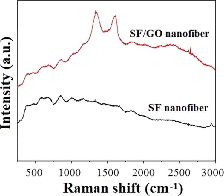
Raman spectra of the SF and SF/GO-blended nanofibers.
The crystalline structures of the electrospinning pure SF and SF/GO-blended nanofibers are identified by XRD, as shown in Figure 4. From Figure 4, it is possible to observe that the GO nanosheets exhibit a distinct peak at 2θ = 11°. According to the Bragg equation 2d sin θ = nλ, the interlayer spacing of our synthesized GO can be calculated as 0.8 nm. Besides, it can be seen that the diffraction angles of the pure SF nanofibers are almost similar to that of the pure SF nanofibers and the diffraction peaks corresponding to GO are not observed, which indicates that SF and GO are evenly blended and the addition of GO does not affect the crystalline structure of SF. Furthermore, the diffraction peak at 2θ = 20.6° (4.5 Å) of the SF/GO-blended nanofibers is sharper than that of the pure SF nanofibers, indicating the presence of faint crystals. Because of the strong interaction between regenerated silk fibroin (RSF) and GO, GO sheets may act as cross-link points among the amorphous RSF chains.32,33
Figure 4.
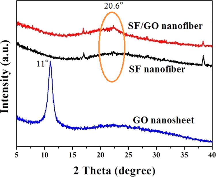
XRD spectra of the SF and SF/GO-blended nanofibers.
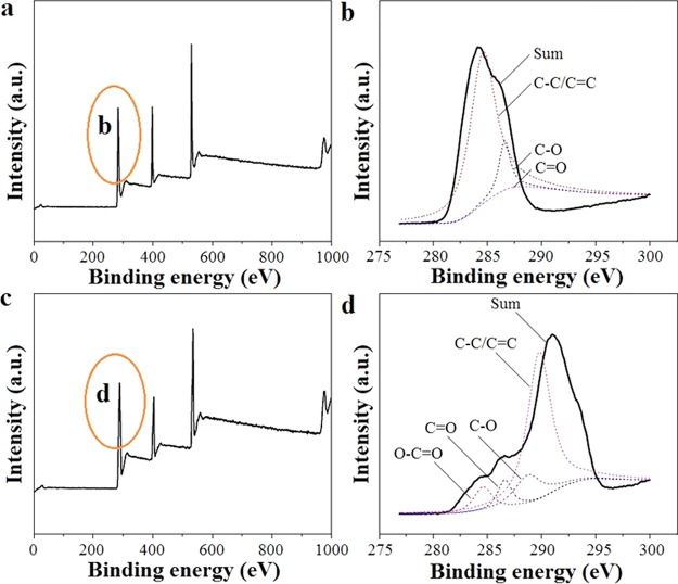
To verify the chemical composition of the electrospinning SF and SF/GO-blended nanofibers, XPS analysis is carried out. Figure 5a,c show the XPS spectra of SF and SF/GO-blended nanofibers, respectively. As shown in Figure 5a,c, it can be seen that there are not any differences between the pure SF and SF/GO-blended nanofibers. Figure 5b,d shows the high-resolution carbon XPS of the SF and SF/GO-blended nanofibers. It could be seen that the carbon element mainly exists in alkyl (284.6 eV), aldehyde (286.9 eV), and carbonyl groups (288.4 eV) than in pure SF scaffold (Table 1). However, it exists in alkyl (284.6 eV), aldehyde (286.9 eV), carbonyl (288.4 eV), and carboxyl groups (289.7 eV). Moreover, the aldehyde group and carboxyl group occupy the main part of the carbon element in SF/GO-blended nanofibers when compared with the pure SF nanofibers. The above results show that blending of GO could induce an increase in the number of oxygen-containing groups. This is probably because blending of GO leads to some new combinations between the SF and GO, such as hydrogen bonds, which is shown in Figure S3a, and these new combinations increase the number of hydrophilic groups and oxygen-containing groups, such as aldehyde, carbonyl, and carboxyl. The formation of hydrogen bonds between SF and GO is confirmed by Fourier transform infrared, as shown in Figure S3b; that is, the characteristic absorption peaks of amide I and amide II of SF did not shift significantly, indicating that blending of GO does not affect the main structure of SF, but the intensity of the hydrophilic group (carboxyl and hydroxyl group) in the SF/GO-blended nanofibers is stronger than that of the pure SF nanofibers.
Figure 5.
XPS curves of the SF (a) and SF/GO-blended nanofibers (c) and high-resolution carbon XPS of the SF (b) and SF/GO-blended nanofibers (d).
Table 1. Binding Energy and Assignment of the C Element in XPS.
| binding energy (eV) | attributable groups |
|---|---|
| 284.6, 285.6 | C–C, C=C |
| 286.9–286.2 | C–O |
| 288.4–287.7 | C=O |
| 289.7–289.0 | O=C–O |
2.4. Antibacterial Activity of the Electrospinning SF/GO-Blended Nanofibers
To investigate the antibacterial activity of the SF/GO-blended nanofibers, Gram-negative Escherichia coli (E. coli) and Gram-positive Staphylococcus aureus (S. aureus) are used; the results are shown in Figure 6. As shown in Figure 6a, the survival rate to E. coli and S. aureus of pure SF nanofibers is (83.9 ± 7.0) and (89.3 ± 4.8)%, respectively, which shows that the SF nanofibers do not have antibacterial property. However, the survival rate to E. coli and S. aureus of SF/GO-blended nanofibers is (35.7 ± 3.6) and (41.6 ± 0.3)%, respectively, which are remarkably (p < 0.05) lower than those of the pure SF nanofibers, indicating that the SF/GO-blended nanofibers have an excellent antibacterial property. To characterize the antibacterial clearly, we chose E. coli to observe its morphology on the surface of the pure SF and SF/GO nanofibers; the results are shown in Figure 7b,c, respectively. It could be seen that the growth of E. coli on pure SF nanofiber is good and the size of bacteria is large. However, E. coli is gradually shrinking on the SF/GO-blended nanofibers and some bacteria have died (Figure 6c, yellow arrow). Moreover, the number of bacteria decreased when compared with the pure SF nanofibers. The antibacterial mechanism of GO is such that the GO can destroy bacterial membranes, leading to the efflux of intracellular material and killing bacteria.34,35
Figure 6.
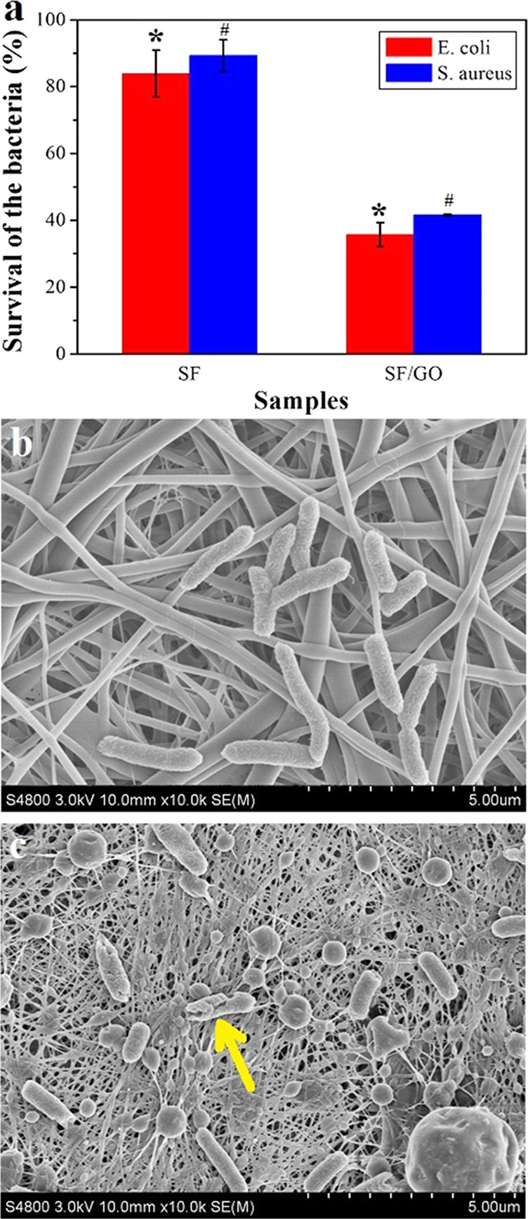
Antibacterial properties (E. coli and S. aureus) of the nanofibers: (a) survival rate of E. coli and S. aureus on the nanofibers, SEM images of the E. coli on the surface of pure SF (b), and SF/GO-blended nanofibers (c), *p < 0.05, #p < 005.
Figure 7.
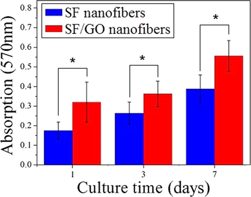
Proliferation of cells on the pure SF and SF/GO-blended nanofibers (*p < 0.05).
2.5. Biocompatibility of the Electrospinning SF/GO-Blended Nanofibers
The (3-(4,5-dimethylthiazol-2-yl)-2,5-diphenyltetrazolium bromide) (MTT) assay is employed to compare the cell viability of the SF/GO-blended nanofibers to that of the pure SF nanofibers (Figure 7). There is a clear temporal proliferation profile of the cells after 1, 3, and 7 days of culture on both SF and SF/GO-blended nanofibers. It follows that cells remained viable on all of the samples. As shown in Figure 7, the cell viability cultures on the SF/GO-blended nanofibers appear significantly higher than that of the pure SF nanofibers at 1, 3, and 7 day time points (p < 0.05). The above result shows that the blending of GO contributes to the proliferation of the cells. This is probably because blending of GO increases the number of oxygen-containing groups, such as aldehyde, carbonyl, and carboxyl, and this is verified by XPS analysis.
Laser confocal microscopy is carried out to study the dynamics of cell adhesion, spreading, and proliferation on the nanofibers after fluorescent straining with fluorescein diacetate, as shown in Figure 8. MC3T3 cells are adhered to and spread on the SF/GO-blended nanofibers after 1 day in culture; these cells show greater cell adherence and a higher degree of spreading than that of the pure SF nanofibers. Compared with the number of cells that adhere to the SF/GO-blended nanofibers (Figure 8b), fewer cells adhere to the pure SF nanofibers (Figure 8a). After 3 days of cell culture, profuse cell growth is observed throughout the SF/GO nanofibers compared with the pure SF nanofibers. After 7 days, MC3T3 cells-seeded SF/GO nanofibers are fully covered with a thick cell multilayer, as well as extracellular matrix possibly concealing the surface of SF/GO-blended nanofibers. These results suggest that cell adhesion, spreading, and proliferation of MC3T3 cells have indeed been improved by SF/GO-blended nanofibers. It is consistent with the MTT analysis.
Figure 8.
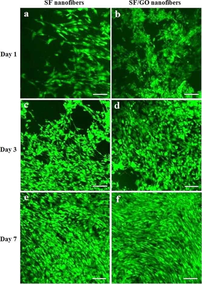
Laser scanning confocal microscope of cells on the SF and SF/GO-blended nanofibers: (a), (c), and (e) cells culture on SF after days 1, 3, and 7, respectively; (b), (d), and (f) cells culture on SF/GO after days 1, 3, and 7, the scale bar is 100 μm.
Figure 9 shows a high-resolution image after 7 days of culture; it can be seen that cells can grow well both on SF and SF/GO-blended nanofibers. However, the proliferation and differentiation of the cells on the blended nanofibers are better and the cells on the blended nanofibers show a spindle shape. The results further prove that the blending of GO is in favor of the cell growth, proliferation, and differentiation.
Figure 9.
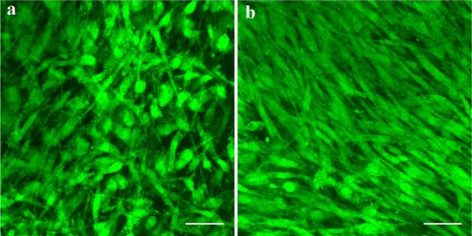
Laser scanning confocal microscope of the cells on SF (a) and SF/GO-blended (b) nanofibers after culturing for 7 days, the scale bar is 50 μm.
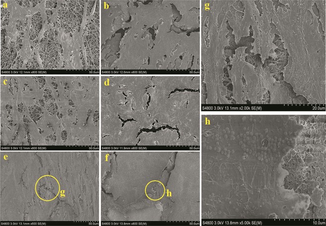
The SEM images exhibit the morphologies of inoculated MC3T3 cells on the pure SF and SF/GO-blended nanofibers, as shown in Figure 10. In comparison with the pure SF nanofibers, MC3T3 cells on the SF/GO-blended nanofibers after 1 and 3 days of cell culture show a much higher degree of spreading. After 7 days, the morphology of MC3T3 cells growing on the SF/GO-blended nanofibers shows a much thicker and denser attachment, the cells form cell sheets, concealing the nanoporous structures of SF/GO-blended nanofibers (Figure 10f,h). The inoculated MC3T3 cells attach and grow much better on the SF/GO-blended nanofibers compared with pure SF nanofibers. The results also prove that the blending of GO is in favor of the cell growth, proliferation, and differentiation.
Figure 10.
SEM images of cells on the SF and SF/GO-blended nanofibers: (a, c, e) cells culture on SF after days 1, 3, and 7, respectively; (b, d, f) cells culture on SF/GO after days 1, 3, and 7, respectively, (g, h) high-resolution SEM images of the cells on SF and SF/GO-blended nanofibers after culturing for 7 days, respectively.
3. Conclusions
In summary, the SF/GO-blended nanofibers with a nano–micro multiscale porous structure are successfully fabricated via electrospinning. SEM and TEM analyses show that GO is successfully blended into SF nanofibers with a globular form of the surface of the nanofibrous membrane. XRD result shows that SF and GO are evenly blended and the addition of GO does not affect the structure of SF and blending of GO induces faint crystals of SF and increases the number of oxygen-containing groups. Our results indicate that blending of GO could improve the antibacterial activity and biocompatibility of SF nanofibers. The relatively simple methodology and the outstanding performance of the multiscale porous SF/GO nanofibers suggest that it possesses extensive potential for application in wound dressing.
4. Experimental Section
4.1. Preparation of the SF/GO Nanofibers
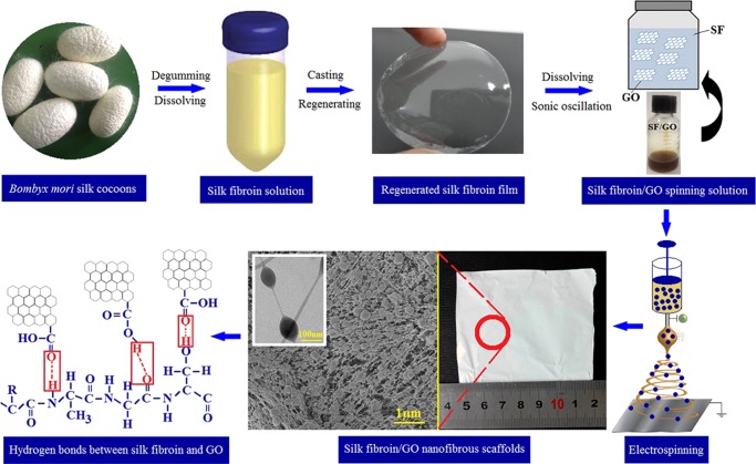
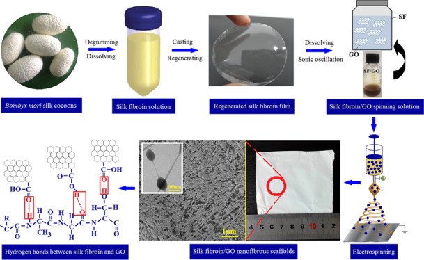
GO nanosheets were prepared from natural graphite powder by a modified Hummers method.36−38Figure 11 shows the schematic illustration of preparation of the SF/GO-blended nanofibers. As shown in Figure 11, the SF aqueous solution was prepared according to our previous research.9 The dialyzed SF aqueous solution was air-dried to obtain the regenerated SF membrane. The air-dried SF regenerated membranes were dissolved in 98% (w/w) formic acid to obtain the SF/formic acid (amount of SF was 13 wt %) solution. Then, the spinning solution is prepared by adding the different GO aqueous solutions (3, 4, and 5 wt %) with concentration of 3 wt % to the SF/formic acid solution. For electrospinning, the voltage is 30 kV, the distance between the needle and collector is 13 cm, and the flow rate of the solution is 0.2 mL/h. As the as-spun SF and SF/GO nanofibers are water soluble, the treatment process was carried out by immersing the nanofibers in ethanol for 15 min after electrospinning. After ethanol treatment, the samples were given a post-treatment to remove residual ethanol.39
Figure 11.
Schematic illustration of preparation of the SF/GO-blended nanofiber.
4.2. Characterization
Viscosity of the spinning solution and morphology of the GO and electrospinning nanofibers are characterized according to the previous research.40 GO aqueous solution is deposited on to the silicon wafer, and the AFM image is obtained by the AFM facility (Bruker, Multimode 8).41 Raman spectra of the GO and electrospinning blended nanofibers were recorded on a Raman microscope (HORIBA Jobin Yvon, HR800) with a 514 nm wavelength laser. Full spectra of elements on the surface of GO and electrospinning blended nanofibers were measured by XPS (model XSAM800, Kratos Co. Ltd., England), and the high-resolution mapping of carbon element was measured. XRD spectra of the electrospinning blended nanofibers were carried out on an X-ray diffractometer with Cu Kα radiation (Philips, X’Pert-Pro MRD).
4.3. Antibacterial Properties of the SF/GO-Blended Nanofibers
The antibacterial property of the electrospinning blended nanofibers was tested against Gram-negative E. coli and Gram-positive S. aureus. Antibacterial activity of the electrospinning blend nanofibers are investigated according to our previous research and FZ/T 73023-2006 (China).42,43 To demonstrate the antibacterial effect more clearly, we chose one kind of bacterial species (E. coli) and observed the morphology of the bacterial species on the electrospinning blended nanofibers by SEM (S-4800, Hitachi), according to ref (44).
4.4. Biological Evaluation Based on in Vitro Cell Culture
For biological evaluation, we use preosteoblast cells MC3T3-E1 to characterize the biocompatibility of the electrospinning blended nanofibers. The method for cell culture is according to refs (15, 45, 46).
4.5. Statistical Analysis
All data were expressed as means ± standard deviations. The statistical significance of differences among each group was examined by the t test. The significance was set at p < 0.05 level.
Acknowledgments
This research is supported by the High Education Science Foundation of Jiangsu Province under Grants 16KJB540005 and a grant from the Top-notch Academic Programs Project of Jiangsu Higher Education Institutions (PPZY2015C254). The authors are grateful for the projects supported by the Open Project Program of Key Laboratory of Eco-textiles, Ministry of Education, Jiangnan University (No. KLET1601). The research is also funded by the Agricultural Support Program of Yancheng, Jiangsu Province (2016012 and 2015028) and Scientific Research Fund of Yancheng Institute of Industry Technology (ygy1505 and ygy1409).
Supporting Information Available
The Supporting Information is available free of charge on the ACS Publications website at DOI: 10.1021/acsomega.7b01210.
Additional SEM of electrospinning SF/GO-blended nanofiber, viscosity of the electrospinning solution, and analysis of the interaction between the SF and GO (PDF)
The authors declare no competing financial interest.
Supplementary Material
References
- Chiono V.; Tonda-Turo C. Trends in the design of nerve guidance channels in peripheral nerve tissue engineering. Prog. Neurobiol. 2015, 131, 87–104. 10.1016/j.pneurobio.2015.06.001. [DOI] [PubMed] [Google Scholar]
- Rockwood D. N.; Preda R. C.; Yücel T.; Wang X. Q.; Lovett M. L.; Kaplan D. L. Materials fabrication from Bombyx mori silk fibroin. Nat. Protoc. 2011, 6, 1612–1631. 10.1038/nprot.2011.379. [DOI] [PMC free article] [PubMed] [Google Scholar]
- Ren K.; Wang Y.; Sun T.; Yue W.; Zhang H. Electrospun PCL/gelatin composite nanofiber structures for effective guided bone regeneration membranes. Mater. Sci. Eng., C 2017, 78, 324–332. 10.1016/j.msec.2017.04.084. [DOI] [PubMed] [Google Scholar]
- Wang S. D.; Zhang Y. Z.; Yin G. B.; Wang H. W.; Dong Z. H. Electrospun polylactide/silk fibroin-gelatin composite tubular scaffolds for small-diameter tissue engineering blood vessels. J. Appl. Polym. Sci. 2009, 113, 2675–2682. 10.1002/app.30346. [DOI] [Google Scholar]
- Shao Z.; Vollrath F. Surprising strength of silkworm silk. Nature 2002, 418, 741. 10.1038/418741a. [DOI] [PubMed] [Google Scholar]
- Wang S. D.; Zhang Y. Z. Preparation of the silk fabric with ultraviolet protection and yellowing resistance using TiO2/La(III) composite nanoparticles. Fibers Polym. 2014, 15, 1129–1136. 10.1007/s12221-014-1129-4. [DOI] [Google Scholar]
- Wang S.; Zhang Y. Z.; Wang H. W.; Dong Z. H. Preparation, characterization and biocompatibility of electrospinning heparin-modified silk fibroin nanofibers. Int. J. Biol. Macromol. 2011, 48, 345–353. 10.1016/j.ijbiomac.2010.12.008. [DOI] [PubMed] [Google Scholar]
- Yin G.-B.; Zhang Y. Z.; Wang S. D.; Shi D. B.; Dong Z. H.; Fu W. G. Study of the electrospun PLA/silk fibroin-gelatin composite nanofibrous scaffold for tissue engineering. J. Biomed. Mater. Res., Part A 2010, 93, 158–163. 10.1002/jbm.a.32496. [DOI] [PubMed] [Google Scholar]
- Wang S. D.; Zhang K. Q. Electrogelation and rapid prototyping of Bombyx mori silk fibroin. Mater. Lett. 2016, 169, 5–9. 10.1016/j.matlet.2016.01.079. [DOI] [Google Scholar]
- Kundu B.; Rajkhowa R.; Kundu S. C.; Wang X. G. Silk fibroin biomaterials for tissue regenerations. Adv. Drug Delivery Rev. 2013, 65, 457–470. 10.1016/j.addr.2012.09.043. [DOI] [PubMed] [Google Scholar]
- Xiao S.; Wang Z.; Ma H.; Yang H.; Xu W. Effective removal of dyes from aqueous solution using ultrafine silk fibroin powder. Adv. Powder Technol. 2014, 25, 574–581. 10.1016/j.apt.2013.09.007. [DOI] [Google Scholar]
- Qi N.; Zhao B.; Wang S. D.; Al-Deyab S. S.; Zhang K. Q. Highly flexible and conductive composite films of silk fibroin and silver nanowires for optoelectronic devices. RSC Adv. 2015, 5, 50878–50882. 10.1039/C5RA03501E. [DOI] [Google Scholar]
- Wang S.; Zhang Y. Z.; Wang H. W.; Yin G. B.; Dong Z. H. Fabrication and properties of the electrospun polylactide/silk fibroin-gelatin composite tubular scaffold. Biomacromolecules 2009, 10, 2240–2244. 10.1021/bm900416b. [DOI] [PubMed] [Google Scholar]
- Wang S. D.; Zhang Y. Z.; Yin G. B.; Wang H. W.; Dong Z. H. Fabrication of a composite vascular scaffold using electrospinning technology. Mater. Sci. Eng., C 2010, 30, 670–676. 10.1016/j.msec.2010.02.021. [DOI] [Google Scholar]
- Yang Y.; Wang H.; Yan F. Y.; Qi Y.; Lai Y. K.; Zeng D. M.; Chen G. Q.; Zhang K. Q. Bioinspired porous octacalcium phosphate/silk fibroin composite coating materials prepared by electrochemical deposition. ACS Appl. Mater. Interfaces 2015, 7, 5634–5642. 10.1021/am5088488. [DOI] [PubMed] [Google Scholar]
- Zeng D. M.; Pan J. J.; Wang Q.; Liu X. F.; Wang H.; Zhang K. Q. Controlling silk fibroin microspheres via molecular weight distribution. Mater. Sci. Eng., C 2015, 50, 226–233. 10.1016/j.msec.2015.02.005. [DOI] [PubMed] [Google Scholar]
- Yang X.; Fan L.; Ma L.; Wang Y.; Lin S.; Yu F.; Pan H.; Luo G.; Zhang D.; Wang H. Green electrospun Manuka honey/silk fibroin fibrous matrices as potential wound dressing. Mater. Des. 2017, 119, 76–84. 10.1016/j.matdes.2017.01.023. [DOI] [Google Scholar]
- Song D. W.; Kim S. H.; Kim H. H.; Lee K. H.; Ki C. S.; Park Y. H. Multi-biofunction of antimicrobial peptide-immobilized silk fibroin nanofiber membrane: implications for wound healing. Acta Biomater. 2016, 39, 146–155. 10.1016/j.actbio.2016.05.008. [DOI] [PubMed] [Google Scholar]
- Calamak S.; Aksoy E. A.; Ertas N.; Erdogdu C.; Sagıroglu M.; Ulubayram K. Ag/silk fibroin nanofibers: effect of fibroin morphology on Ag+ release and antibacterial activity. Eur. Polym. J. 2015, 67, 99–112. 10.1016/j.eurpolymj.2015.03.068. [DOI] [Google Scholar]
- Zhang X. L.; Jia C. L.; Qiao X. Y.; Liu T. Y.; Sun K. Silk fibroin microfibers and chitosan modified poly (glycerol sebacate) composite scaffolds for skin tissue engineering. Polym. Test. 2017, 62, 88–95. 10.1016/j.polymertesting.2017.06.012. [DOI] [Google Scholar]
- Hu X. J.; Li J. G.; Bai Y. X. Fabrication of high strength graphene/regenerated silk fibroin composite fibers by wet spinning. Mater. Lett. 2017, 194, 224–226. 10.1016/j.matlet.2017.02.057. [DOI] [Google Scholar]
- Akhavan O.; Ghaderi E. Toxicity of graphene and graphene oxide nanowalls against bacteria. ACS Nano 2010, 4, 5731–5736. 10.1021/nn101390x. [DOI] [PubMed] [Google Scholar]
- Diban N.; Sánchez-González S.; Lázaro-Díez M.; Ramos-Vivas J.; Urtiaga A. Facile fabrication of poly(ε-caprolactone)/graphene oxide membranes for bioreactors in tissue engineering. J. Membr. Sci. 2017, 540, 219–228. 10.1016/j.memsci.2017.06.052. [DOI] [Google Scholar]
- Ruiz O. N.; Fernando K. A. S.; Wang B. J.; Brown N. A.; Luo P. J.; McNamara N. D.; Vangsness M.; Sun Y. P.; Bunker C. E. Graphene oxide: a nonspecific enhancer of cellular growth. ACS Nano 2011, 5, 8100–8107. 10.1021/nn202699t. [DOI] [PubMed] [Google Scholar]
- Liu S.; Hu M.; Zeng T. H.; Wu R.; Jiang R.; Wei J.; Wang L.; Kong J.; Chen Y. Lateral dimension-dependent antibacterial activity of graphene oxide sheets. Langmuir 2012, 28, 12364–12372. 10.1021/la3023908. [DOI] [PubMed] [Google Scholar]
- Bai H.; Li C.; Wang X. L.; Shi G. Q. On the gelation of graphene oxide. J. Phys. Chem. C 2011, 115, 5545–5551. 10.1021/jp1120299. [DOI] [Google Scholar]
- Kudin K. N.; Ozbas B.; Schniepp H. C.; Prud’homme R. K.; Aksay I. A.; Car R. Raman spectra of graphite oxide and functionalized graphene sheets. Nano Lett. 2008, 8, 36–41. 10.1021/nl071822y. [DOI] [PubMed] [Google Scholar]
- Li C.; Shi G. Q. Three-dimensional graphene architectures. Nanoscale 2012, 4, 5549–5563. 10.1039/c2nr31467c. [DOI] [PubMed] [Google Scholar]
- Li D.; Muller M. B.; Gilje S.; Kaner R. B.; Wallace G. G. Processable aqueous dispersions of graphene nanosheets. Nat. Nanotechnol. 2008, 3, 101–105. 10.1038/nnano.2007.451. [DOI] [PubMed] [Google Scholar]
- Bourlinos A. B.; Stassinopoulos A.; Anglos D.; Zboril R.; Karakassides M.; Giannelis E. P. Surface functionalized carbogenic quantum dots. Small 2008, 4, 455–458. 10.1002/smll.200700578. [DOI] [PubMed] [Google Scholar]
- Wang F.; Kreiter M.; He B.; Pang S.; Liu C. Synthesis of direct white-light emitting carbogenic quantum dots. Chem. Commun. 2010, 46, 3309–3311. 10.1039/c002206c. [DOI] [PubMed] [Google Scholar]
- Zhang C.; Zhang Y.; Luo J.; Shi J.; Shao H.; Hu X. Microstructural evolution of regenerated silk fibroin/graphene oxide hybrid fibers under tensile deformation. RSC Adv. 2017, 7, 3108–3116. 10.1039/C6RA22544F. [DOI] [Google Scholar]
- Zhang C.; Zhang Y.; Shao H.; Hu X. Hybrid silk fibers dry-spun from regenerated silk fibroin/graphene oxide aqueous solutions. ACS Appl. Mater. Interfaces 2016, 8, 3349–3358. 10.1021/acsami.5b11245. [DOI] [PubMed] [Google Scholar]
- Hu W.; Peng C.; Luo W. J.; Lv M.; Li X. M.; Li D.; Huang Q.; Fan C. H. Graphene-based antibacterial paper. ACS Nano 2010, 4, 4317–4323. 10.1021/nn101097v. [DOI] [PubMed] [Google Scholar]
- Tu Y.; Lv M.; Xiu P.; Huynh T.; Zhang M.; Castelli M.; Liu Z.; Huang Q.; Fan C.; Fang H.; Zhou R. Destructive extraction of phospholipids from Escherichia coli membranes by graphene nanosheets. Nat. Nanotechnol. 2013, 8, 594–601. 10.1038/nnano.2013.125. [DOI] [PubMed] [Google Scholar]
- Hummers W. S. Jr.; Offeman R. E. Preparation of graphitic oxide. J. Am. Chem. Soc. 1958, 80, 1339. 10.1021/ja01539a017. [DOI] [Google Scholar]
- Xu Y.; Wu Q.; Sun Y. Q.; Bai H.; Shi G. Q. Three-dimensional self-assembly of graphene oxide and DNA into multifunctional hydrogels. ACS Nano 2010, 4, 7358–7362. 10.1021/nn1027104. [DOI] [PubMed] [Google Scholar]
- Abdulkhani A.; Sousefi M. D.; Ashori A.; Ebrahimi G. Preparation and characterization of sodium carboxymethyl cellulose/silk fibroin/graphene oxide nanocomposite films. Polym. Test. 2016, 52, 218–224. 10.1016/j.polymertesting.2016.03.020. [DOI] [Google Scholar]
- Zhang Y. Z.; Venugopal J.; Huang Z. M.; Lim C. T.; Ramakrishna S. Crosslinking of the electrospun gelatin. Polymer 2006, 47, 2911–2917. 10.1016/j.polymer.2006.02.046. [DOI] [Google Scholar]
- Chen H.; Ma Q.; Wang S. D.; Liu H.; Wang K. Morphology, compatibility, physical and thermoregulated properties of the electrospinning polyamide 6 and polyethylene glycol blended nanofibers. J. Ind. Text. 2016, 45, 1490–1503. 10.1177/1528083714562089. [DOI] [Google Scholar]
- Huang L.; Li C.; Yuan W.; Shi G. Strong composite films with layered structures prepared by casting silk fibroin-graphene oxide hydrogels. Nanoscale 2013, 5, 3780–3786. 10.1039/c3nr00196b. [DOI] [PubMed] [Google Scholar]
- Qu C. X.; Wang S. D.; Wang K.; Ma Q. Preparation and antibacterial property of the mulberry based textiles. Fibers Polym. 2014, 15, 498–503. 10.1007/s12221-014-0498-z. [DOI] [Google Scholar]
- Wang K.; Ma Q.; Wang S. D.; Liu H.; Zhang S. Z.; Bao W.; Zhang K. Q.; Ling L. Z. Electrospinning of silver nanoparticles loaded highly porous cellulose acetate nanofibrous membrane for treatment of dye wastewater. Appl. Phys. A: Mater. Sci. Process. 2016, 122, 40 10.1007/s00339-015-9566-5. [DOI] [Google Scholar]
- Liu S.; Zeng T.; Hofmann M.; Burcombe E.; Wei J.; Jiang R.; Kong J.; Chen Y. Antibacterial activity of graphite, graphite oxide, graphene oxide, and reduced graphene oxide: membrane and oxidative stress. ACS Nano 2011, 5, 6971–6980. 10.1021/nn202451x. [DOI] [PubMed] [Google Scholar]
- Zhang Y.; Ouyang H. W.; Lim C. T.; Ramakrishna S.; Huang Z. M. Electrospinning of gelatin fibers and gelatin/PCL composite fibrous scaffolds. J. Biomed. Mater. Res., Part B 2005, 72, 156–165. 10.1002/jbm.b.30128. [DOI] [PubMed] [Google Scholar]
- Wang H.; Lin C.; Hu R.; Zhang F.; Lin L. A novel nano-micro structured octacalcium phosphate/protein composite coating on titanium by using an electrochemically induced deposition. J. Biomed. Mater. Res., Part A 2008, 87, 698–705. 10.1002/jbm.a.31653. [DOI] [PubMed] [Google Scholar]
Associated Data
This section collects any data citations, data availability statements, or supplementary materials included in this article.


