Abstract
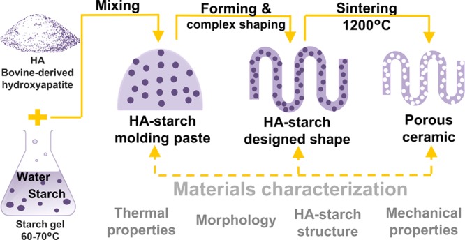
Hydroxyapatite–starch composites solidify rapidly via jellification, making them suitable candidates for robocasting. However, many aspects related to hydroxyapatite powder characteristics, hydroxyapatite–starch interaction, and composites composition and properties need to be aligned with robocasting requirements to achieve a notable improvement in the functionality of printed scaffolds intended for bone regeneration. This article presents a preliminary evaluation of hydroxyapatite–starch microcomposites. Thermal analysis of the starting powders was performed for predicting composites’ behavior during heat-induced densification. Also, morphology, mechanical properties, and hydroxyapatite–starch interaction were evaluated for the jellified composites and the porous bodies obtained after conventional sintering, for different starch additions, and for ceramic particle size distributions. The results indicate that starch could be used for hydroxyapatite consolidation in limited quantities, whereas the composites shall be processed under controlled temperature. Due to a different mechanical behavior induced by particle size and geometry, a wide particle size distribution of hydroxyapatite powder is recommended for further robocasting ink development.
1. Introduction
Building ceramic scaffolds that provide a suitable environment for bone regeneration faces significant challenges. Besides the requirements related to materials and fabrication technologies, a bone scaffold should ensure both adequate porosity (for bone formation and vascularization) and mechanical strength necessary during the initial phases of bone recovery.1,2 Various materials are currently considered for scaffold fabrication. Calcium phosphates such as hydroxyapatite (HA), α-tricalcium phosphate (α-TCP), and β-tricalcium phosphate (β-TCP) are often the materials of choice for bone scaffolds, given their similarity with the mineral component of the bone.2
Calcium phosphate scaffolds can be fabricated through both conventional1 or additive manufacturing methods.3 Robocasting,4 an additive manufacturing method closely related with “direct ink writing”,5 “direct write assembly”,6,7 and “(micro-)robotic deposition”,8,9 has gained interest for fabrication of bone scaffolds because it is able to provide a high mechanical quality to the printed products while being adaptable for a wide range of materials.10
Robocasting involves the extrusion (at low temperatures and pressures) of an ink filament followed by fusion with the previously extruded filaments (by means of superficial tension). Because the quality of robocasted parts is mainly influenced by the ink composition and properties, a suitable ink formulation shall be homogeneous, adequate for extrusion through fine nozzles, and able to rapidly solidify to self-sustain after extrusion. On the one hand, precursor selection has a significant impact in ink development: main criteria are related to particle dimension, geometry, and size distribution of the powders. Micrometric particle sizes (lower than the diameter of robocasting nozzles) are required for preventing ink jamming during extrusion. Also, particle geometry and size distribution shall enhance ink consolidation and prevent the formation of air bubbles that may compromise ink’s mechanical stability after extrusion.3,7,10,11 On the other hand, binder selection and dosing contribute greatly to the preparation of a homogeneous dispersion with a high ceramic content (which shall prevent excessive shrinkage during drying and subsequent densification). Rapid solidification (by coagulation, evaporation, jellification, etc.) of the binder–powder mixture shall ensure the self-sustaining ability of the ink.12 Moreover, biomedical applications shall comply with additional requirements regarding binder’s lack of toxicity and its complete and safe degradation during manufacturing. Adequate levels of microporosity shall also be ensured by the ink during robocasting of bone scaffolds (whereas macroporosity shall be ensured by scaffold design).
Water-based formulations with HA and/or β-TCP have already been proposed as robocasting inks because they are considered simple to prepare, low-priced, and nontoxic. Preparation of water-based inks with calcium phosphates also includes the addition of low amounts of polymers as dispersants, viscosifiers, jellifying, and antifoaming agents.6,10,13
The current study aims to broaden the materials palette for robocasting by proposing starch as a jellifying agent for water-based formulations with hydroxyapatite. Starch is a natural polymer found in vegetables such as potatoes, rice, and corn, and was used in hydroxyapatite mainly as a pore-forming agent,14,15 but various methods of ceramic consolidation based on starch jellification were also proposed.16,17
As robocasting represents both a major opportunity and a challenge for fabrication of ceramic components with stringent design requirements, this study presents the initial evaluation of HA–starch formulations in terms of morphology, mechanical properties, and hydroxyapatite–starch structure. A testification of the application of hydroxyapatite–starch formulations for robocasting, which shall involve extensive material characterization, including rheological, biological, and additional mechanical testing, will be covered in a future study.
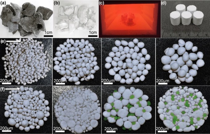
Bovine bone-derived HA and food grade corn starch were chosen as powder precursors due to their proven suitability for biomedical applications.2,18 HA–starch samples were prepared with water, without using other additives. Starch concentration and HA particle size distribution were the main variables evaluated in the study; valuable insights related to particle size and geometry were also included. The investigation of hydroxyapatite–starch formulations with different compositions, which began with a thermal analysis of raw starch and hydroxyapatite powders (derived from bovine bone), was performed for predicting the materials’ behavior during heat-induced densification. Next, composites based on HA and various quantities of starch were evaluated in terms of morphology, structure, and mechanical properties. Finally, full densification of jellified composites was achieved by conventional sintering, which also allowed starch removal and pore formation; the thermal-treated materials were evaluated in comparison with jellified ones (Figure 1).
Figure 1.
Graphical representation of preparation method for jellified HA–starch composites: (a) deproteinized bovine bone; (b) HA after bone thermal treatment at 1000 °C; (c) pressed samples during thermal treatment; (d) specimens used for characterization; (e) representation of powders sorts used for samples preparation; and (f) representation of HA–starch materials after pressing and thermal treatment.
Throughout the study, the as-prepared hydroxyapatite powder is coded “HA a.p.” and initial corn starch powder is described as “raw starch”. The jellified and thermal-treated HA–starch samples are distinguished by the terms “jellified” and “thermal-treated” followed by starch content (wt %): 0, 5, 10, 25, and 50%, respectively.
2. Results and Discussion
2.1. Thermal Behavior of Powdered Precursors
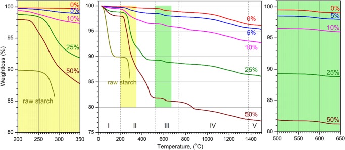
Five distinct domains of thermal transformations/decompositions are identified by thermogravimetric analysis (TGA) during heating in air (Figure 2). The first heating domain (denoted I), from room temperature (RT) to 200 °C, shows a ∼10% weight loss in raw starch and a ∼0.2% weight loss in the as-prepared (a.p.) HA powder. The second heating domain (II), from 200 to ∼520 °C, shows a ∼0.34% weight loss in HA a.p. and a 3.8% weight loss in raw starch. Thermal analysis of raw starch is recorded up to 288 °C; above this temperature, the gas accumulated during the heat-induced reactions leads to a violent burst, so the differential scanning calorimetry (DSC)/TGA data are not reliable. The third heating domain (III), from 520 to ∼740 °C, shows a 0.65% weight loss in HA a.p. The fourth heating domain (IV), 740–1379 °C, shows a ∼2.5% weight loss in HA a.p. The last domain (V), 1379–1500 °C, shows a ∼0.23% weight loss in HA a.p.
Figure 2.
TGA curves of HA a.p., raw starch, and HA–starch mixed powders. Starch content is expressed as weight percent.
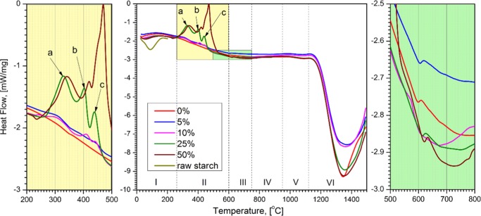
The DSC data show different domains of exothermic and endothermic transformations that accompany the thermal decompositions (Figure 3 and Table 1). The first domain of DSC (denoted I), selected from RT to 250 °C, contains a large exothermic peak of HA a.p. and a strong endothermic peak of starch, both of which cover transformations I and II observed by the TGA. The second domain, 250–600 °C (II), contained a weak and large exothermic peak of HA and three exothermic peaks (a–c) given by the presence of starch in HA. The third domain, 600–750 °C, includes a weak exothermic peak given by HA. The fourth to sixth domains contain two weak (IV and V) and one strong (VI) endothermic peaks that belong to HA.
Figure 3.
DSC curves of HA a.p., raw starch, and HA–starch mixed powders. Starch content is expressed as weight percent.
Table 1. DSC Transformation Stages (as in Figure 3), Type, Onset/Offset Temperatures of Transformation, and the Weight Loss at the Offset Temperature for HA a.p., Raw Starch, and HA–Starch Mixed Powders.
| DSC (heating in air) |
||||
|---|---|---|---|---|
| stage | type | Tonset (°C) | Toffset (°C) | weight loss at Toffset (%) |
| Raw Starch | ||||
| I | endo | 53.3 | 150.9 | 10 |
| HA a.p. | ||||
| I | exo | 76 | 348 | 0.4 |
| II | exo | 362 | 594 | 0.8 |
| III | exo | 602 | 747 | 1.2 |
| IV | endo | 848 | 950 | 1.5 |
| V | endo | 996 | 1114 | 2.1 |
| VI | endo | 1189 | 1431 | 3.8 |
| 50% HA–50% Starch | ||||
| a | exo | 304 | 384 | 13.3 |
| b | exo | 401 | 427 | 14.9 |
| c | exo | 433 | 519 | 18.2 |
The endothermic transformation of starch is assigned to gelatinization19 and evaporation of excessive water, as seen in the TGA data (Figure 2). The thermal effects induced by starch can be observed in the mixed HA–starch powders starting with 200 °C. The starch successively decomposes with temperature (domains II–V, Figure 2).
HA undergoes a succession of thermal transformations/decompositions (Figure 3 and Table 1), also accompanied by weight loss. The weight loss at low temperatures is assigned to evaporation of adsorbed water and hydroxyl groups on the surface of HA.20,21 Thermal stability of HA in air atmosphere is proved until up to ∼1200 °C.
2.2. Morphology Evolution during Preparation of HA–Starch Samples
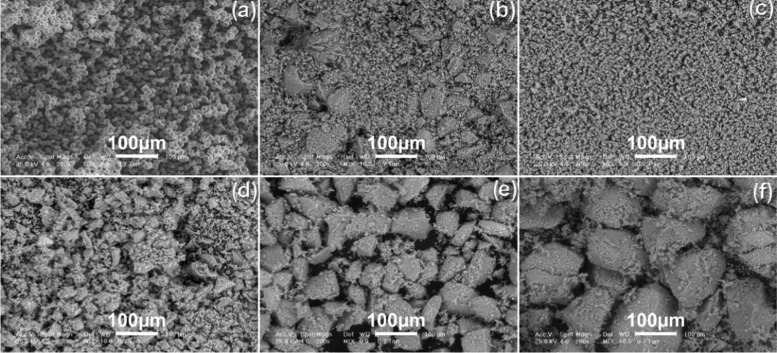
HA and starch powders morphologies are comparatively represented in Figure 4. The raw starch powder consists of spherical particles with smooth surfaces and 10–20 μm particle size. The HA a.p. has different morphologies based on particle size distribution. The mixed HA powder (Figure 4b), prepared from a mix of equal amounts of four types of sorted powders—namely 25 wt % particles sized <20 μm + 25 wt % particles sized <50 μm + 25 wt % particles sized <100 μm + 25 wt % particles sized <200 μm—consisted of particles similar with corresponding granulometric sorts presented in Figure 4c–f. Particles are distributed randomly, with smaller-sized particles filling in the interstices between the larger ones. HA particles smaller than 100 μm (Figure 4c–e) are preponderantly polyhedral (with few elongated particles) with sharp edges and coarse surfaces.
Figure 4.
Initial powders morphology: (a) raw starch; and HA a.p. with different particle sizes: (b) mixed HA (equal parts of sorts presented in (c)–(f)); (c) <20 μm; (d) <50 μm; (e) <100 μm; and (f) <200 μm.
The sorted powder, sized 100–200 μm (Figure 4f), consists of polyhedral particles with rounded edges. The surface of the larger particles is covered with agglomerations of small-sized particles (<20 μm). HA particles surface has small-sized pores that remain after the removal of bone organics during thermal treatment,22 and some of the particles have cracks generated by milling and sorting.
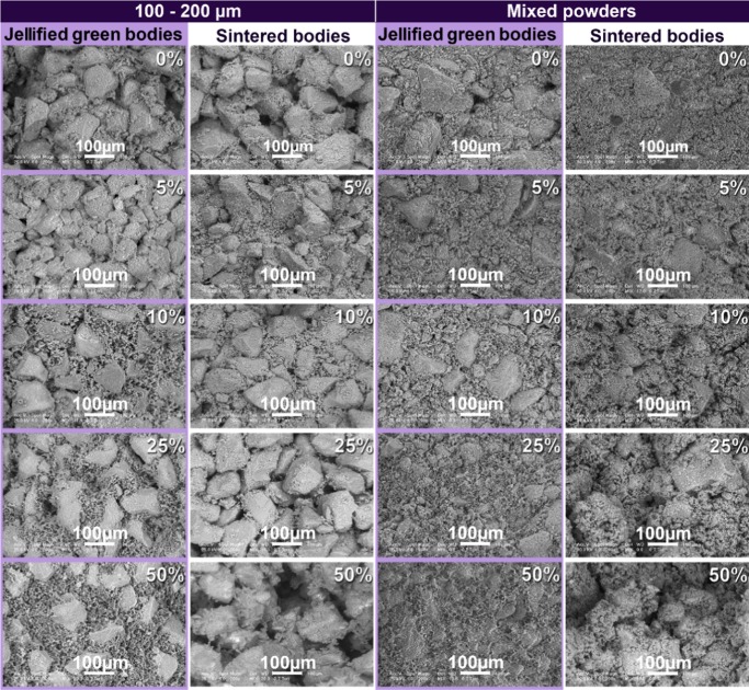
The morphologies of jellified composites and thermal-treated bodies are presented comparatively in Figure 5 for different starch concentrations and particle size distributions. The control samples consisting of HA without starch are included in the analysis for evaluation.
Figure 5.
Morphology of jellified and thermal-treated HA–starch composites prepared with sorted (100–200 μm) and mixed HA powders. Starch content is expressed as weight percent on each scanning electron microscopy (SEM) micrograph.
The jellified materials prepared with sorted HA powders (100–200 μm) and different starch quantities (left column in Figure 5) consisted of polyhedral ceramic particles well represented within the consolidated bodies. The samples contained pores with various shapes and dimensions. Addition of starch in low concentrations (HA with 5 wt % starch) leads to a better packing of the samples due to pores filling. In the samples with starch additions higher than 10 wt %, the spherical (darker) starch particles are unified in a polymeric network, which encloses the HA particles.
Starch addition ensures a bimodal particle size distribution, which contributes to porosity decrease and better consolidation of the jellified body (first and third column in Figure 5); this observation is supported by similar results, in which the starch addition to HA leads to the preparation of cements with compact morphologies and enhanced mechanical characteristics.23 The use of mixed powders leads to an enhanced packing of jellified bodies, their porosity being significantly reduced compared with the samples prepared with sorted HA (Figure 5, third vs first column from left to right).
Ceramic body consolidation is achieved mainly by starch jellification. Starch jellifies in aqueous solutions, at 60–80 °C. The process begins with the swelling of starch grains, whereas their crystalline regions are damaged. These damaged regions are then adsorbed at the ceramic particles surface; this enhances the mechanical strength of the consolidated body.18,24 The influence of starch addition upon the morphology is best observed in the samples with higher starch concentrations (25–50 wt %) in which the large ceramic particles are covered with gel scales consisting of starch and small HA particles.
Thermal treatment leads to thermal degradation and removal of starch and the formation of porous ceramic bodies consisting of consolidated large particles covered with smaller particles. The porosity corresponds to the shape and quantity of jellified starch. In the sintered samples (second and fourth columns in Figure 5), the size and shape of hydroxyapatite particles do not suffer any significant modifications as a consequence of sintering, thus confirming that sintering does not influence the ceramic’s morphology.
The degradable starch filler is completely removed after the thermal treatment is performed at 1200 °C. As a consequence of thermal degradation, the spaces initially filled starch are replaced by randomly distributed pores. The shape and quantity of these pores correspond to the shape and quantity of starch filler in the jellified samples (as noted in previous studies25), so the samples that initially contained higher starch quantities exhibit an increased porosity as compared with the hydroxyapatite samples prepared without starch.
2.3. X-ray Diffraction (XRD)
The XRD patterns of the HA as-prepared (a.p.) powder and heat-treated HA–starch samples are presented comparatively in Figure 6. For evaluation we have also included in Figure 6 the pattern of the as-jellified 50% HA–50% starch sample, as well as the diagrams of two control samples: simple HA powder thermal-treated samples (i) in the absence and (ii) in the presence of HA–starch.
Figure 6.
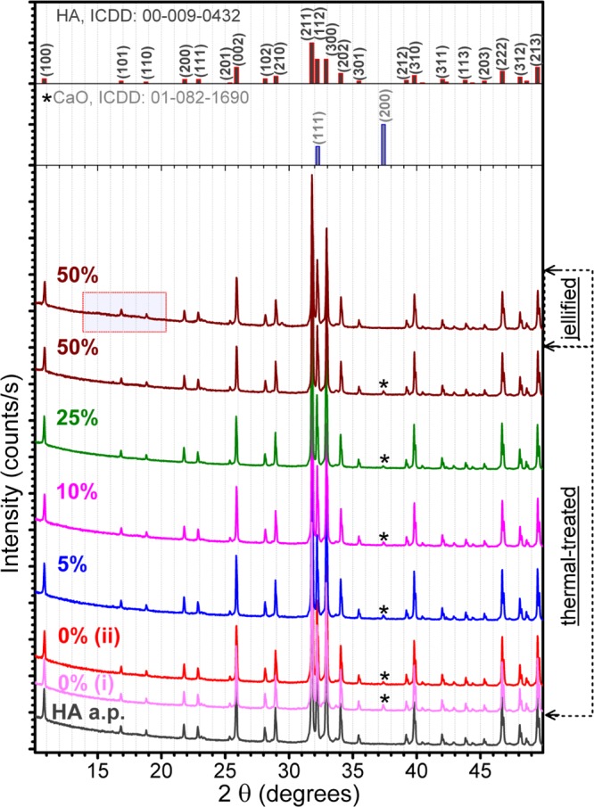
Comparative XRD patterns of the simple HA powder, and HA–starch blends, before and after their thermal treatment in air.
The presence of starch can be highlighted by XRD only in the case of 50% HA–50% starch jellified sample, as fade humps in the 2θ ≈ 10–22° range (the corresponding highlighted region in Figure 6 is presented enlarged in Figure 7). This is due to the reduced crystalline status (Figure 7) and low density of starch, which translates into a lower diffracted intensity. For lower starch contents, the signal is buried in the background noise. From the comparison of the raw and jellified starch powders (Figure 7), we can deduce that no modification at long-range order occurs in the starch structure during the jellification process.
Figure 7.
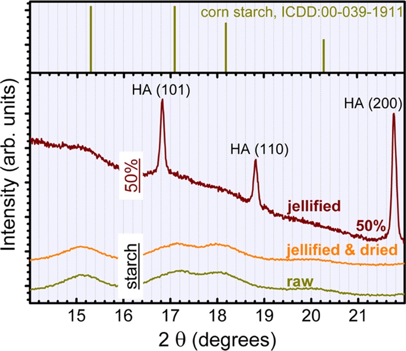
XRD pattern of unannealed 50% HA–50% starch blend presented comparatively to the patterns of raw starch and jellified and dried starch powders.
After the thermal-treatment has been applied (i.e., 1200 °C/4 h in air) to the HA–starch, no significant structural modifications can be detected by XRD, apart from the appearance as a residual secondary phase of calcium oxide (CaO) (Figure 6, starred peak). Both, the mean crystalline size (∼250 nm) and lattice parameters (a = 9.419 Å; c = 6.882 Å) of HA, were found to be fairly constant in the case of all of the sintered blends. The content of CaO does not appear to be influenced by the presence of starch (Figure 6); its amount, estimated by Rietveld full-pattern structure refinement method, is in the range 0.35–0.70 wt % for all of the samples. Furthermore, the presence of CaO in similar concentration in both simple HA powder batches—(i) heat-treated in the absence and (ii) presence of HA–starch—strengthens our hypothesis. One can note that the ISO 13779 standards,26,27 which regulate the fabrication of implants, state that a content of maximum 5 wt % of impurity phases (i.e., α-tricalcium phosphate, β-tricalcium phosphate, tetracalcium phosphate, and/or CaO) in HA materials is considered as acceptable for clinical applications. Consequently, the composition of the materials proposed in this study is situated significantly below the limit imposed by the ISO 13779 standard.
The formation of the crystalline CaO phase during thermal processing of HA can be considered rather rare. In literature, three possible hydroxyapatite decomposition reactions have been advanced (eq 1 (refs (28−31)); eq 2 (refs (28−32)); eq 3 (ref (33)))
| 1 |
| 2 |
| 3 |
The absence of tricalcium phosphate, either in crystalline—XRD (Figure 6) or amorphous—Fourier transform infrared (FTIR) (Figure 9) forms, in the case of all of the thermal-treated samples suggests eq 3 as partial decomposition route of hydroxyapatite. Kim et al.33 associate this partial conversion of HA into crystalline CaO to its severe dehydroxylation. This is to be expected when performing a second sintering procedure, as was the case of our studies. The absence of P2O5 as the crystalline phase (Figure 6) can be explained by its low sublimation temperature (∼300 °C).33 The binary CaO–P2O5 equilibrium phase diagram2,28,32,34 suggests that phases such as CaO or P2O5 cannot easily emerge in the system at temperatures lower than 1720 °C. However, our result is not unprecedented, as previous studies have shown that CaO can form even at 1000 °C in the case of HA materials with a Ca/P molar ratios higher than the stoichiometric theoretical value (i.e., 1.67).35,36
Figure 9.
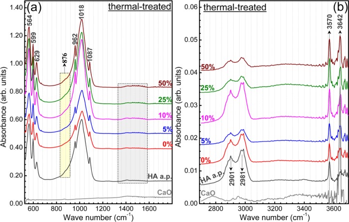
Comparative FTIR spectra of the simple HA, and CaO powders, and thermal-treated HA–starch blends, collected in the fingerprint (a) and functional groups (b) regions.
2.4. FTIR Spectroscopy Measurements
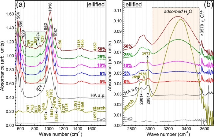
The FTIR spectra of the as-jellified and thermal-treated HA–starch blends are presented in Figures 8 and 9, respectively. For an easy visualization of the IR spectra details, they are presented in the fingerprint (Figures 8a and 9a) and functional groups (Figures 8b and 9b) separate wave numbers regions. The spectra of HA a.p. and starch starting materials, as well as of a pure CaO (Sigma-Aldrich) powder, are presented in Figures 8 and 9 for comparison purposes.
Figure 8.
Comparative FTIR spectra of the simple HA, CaO, and starch powders, and unannealed HA–starch blends, collected in the fingerprint (a) and functional groups (b) regions.
Typical IR envelopes of hydroxyapatite37 have been recorded by FTIR in the case of all HA–starch blends (Figure 8). All of the characteristic vibration bands of hydroxyapatite have been identified: libration (∼629 cm–1) and stretching modes (∼3570 cm–1) of hydroxyl structural groups and ν4 bending (∼560–600 cm–1), ν1 symmetric stretching (∼962 cm–1), and ν3 asymmetric stretching (1000–1090 cm–1) modes of orthophosphate groups.37−39
In the case of the blends, part of the starch IR bands are overlapped by the more intense HA maxima, and thus obscured. A complete assignment of both HA and starch bands is given in Table 2. In the regions of lower HA absorption (Figure 10a), the vibration bands of starch can be easily depicted, having a similar intensity ratio and presenting no wavelength shifts with respect to the raw powder (Figure 8): out-of-phase bending of hydrogen-bonded OH– groups (709 cm–1), rocking of −CH2 groups (763 cm–1), bending modes of C–H bonds (857 cm–1), vibration in rings and bending of C–O (929 cm–1), stretching vibrations of C–O–C and C–O–H bonds (1050 cm–1), and bending (1652 cm–1) and stretching (2500–3600 cm–1) of adsorbed water molecules.37,40−42 This gives a first indication that the starch structure is not strongly modified during the jellification process, and thus, supports the XRD findings (Figure 7).
Table 2. FTIR Bands Assignment of Hydroxyapatite–Starch Samples.
| position (cm–1) | band assignment |
|---|---|
| 564, 599 | bending ν4 of (PO4)3– groups37−39 |
| 629 | libration of structural (OH)− groups37−39 |
| 709 | out-of-phase bending of hydrogen bonded OH– groups40−42 |
| 763 | rocking of –CH2 groups40−42 |
| 857 | bending modes of C–H bonds40−42 |
| 874–876 | bending ν2 of (CO3)2– groups37−39 |
| 929–930 | vibration modes in rings; bending of C–O40−42 |
| 957 | bending of C–O–C, C–O–H; stretching of CO40−42 |
| 962 | symmetric stretching ν1 of (PO4)3– groups37−39 |
| 1018, 1087 | asymmetric stretching ν3 of (PO4)3– groups37−39 |
| 997, 1012, 1041, 1078, 1105, 1150, 1207, 1245 | various stretching vibrations of C–O–C and C–O–H bonds40−42 |
| 1381 | in plane bending of –CH groups40−42 |
| 1414 | stretching vibration of C–C bonds40−42 |
| asymmetric stretching ν3 of (CO3)2– groups37−39 | |
| 1460 | in plane bending of –CH2 groups40−42 |
| asymmetric stretching ν3 of (CO3)2– groups37−39 | |
| 1652 | bending of water molecules37−39 |
| 2890–2901 | symmetric stretching ν2 of C–H bonds in –CH2 groups40−42 |
| 2928 | symmetric stretching of C–H bonds in benzene rings40−42 |
| 2972–2981 | asymmetric stretching of –CH240−42 |
| 3570 | stretching of structural (OH)− groups37−39 |
| 3642 | stretching vibrations of (OH)− groups of surface Ca(OH)2 compounds49−51 |
| 2500–3600 | stretching vibrations of O–H bonds in adsorbed water molecules37−39 |
Figure 10.
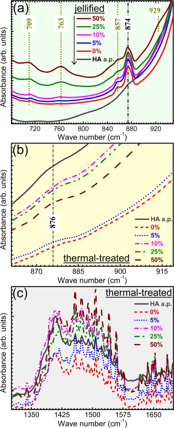
Zoomed FTIR regions of the wave numbers domains highlighted in (a): Figure 8a; (b) Figure 9a; and (c) Figure 9a.
The higher the starch content in the materials, the more prominent its bands are, and more significant is the level of material hydration (Figure 8).
However, slight band shifts are signalled in the case of the stretching vibrations of C–C bonds (from 1414 to 1418 cm–1) and in-plane bending vibrations of −CH2 groups (from 1460 to 1456 cm–1) between pure starch and HA–starch blends (Figure 8a). This is attributed to the superposition in this specific region of the ν3 asymmetric stretching bands of carbonate groups present in the structure of HA,37−39 which results in the modification of the peaks profile. The presence of carbonate groups in the structure of HA is supported also by the shallow band positioned at ∼874 cm–1, in case of both HA a.p. and HA–starch jellified blends, ascribed to the bending vibrations of carbonate groups.37−39 Carbonatation is typical of HA materials derived from animal bones.43,44
Further, insightful comparative FTIR measurements have been performed on starch found in three forms: raw, jellified, and jellified and dried at room temperature (Figure 11). Upon jellification, the starch uptakes significant amount of water, as demonstrated by the intensity increase of bands corresponding to bending (1652 cm–1) and stretching vibrations of adsorbed water molecules (2500–3600 cm–1). Apart from this, one can notice modifications in the intensity ratio of symmetric stretching of (C–H) bonds in benzene rings (2928 cm–1) and asymmetric stretching of (−CH2) groups (2972 cm–1) bands (Figure 11, inset). This suggests that slight perturbations of these specific chemical environments occur.
Figure 11.
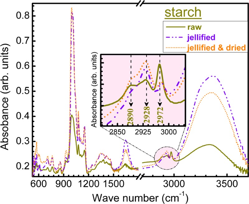
Comparative FTIR spectra of starch in raw, jellified, and jellified and dried form. Inset: zoomed region of C–H stretching bands wave numbers domain (2800–3100 cm–1).
The doubly split bands positioned in the 2800–3000 cm–1 region (Figures 8b and 9b), observed also in the case of simple HA a.p. powder, are assigned to the various C–H stretching vibrations determined by adventitious hydrocarbon contamination of samples during handling and storing in ambient. Their shape is modified only in the case of higher concentrations of starch in the blends.
In the case of thermal-treated HA–starch blends (Figure 9), one can notice the disappearance of all of the starch IR bands. Concurrently, the hydroxyapatite bands’ position and allure (Figure 9a) are preserved with respect to the jellified blended samples and HA a.p. control (Figure 8a). This points toward the excellent capability of the chosen thermal route to eliminate the starch from the scaffold bodies and conserve unaltered the structure of the HA material. The carbonatation of HA, which is known to elicit remarkable biological properties,39,45−48 has been fairly well maintained (Figure 10b,c) after sintering. The presence of C–H stretching vibrations due to adventitious hydrocarbon contamination has been evidenced also in the case of the thermal-treated samples (Figure 9b). Their intensity varies as a function of the haphazard degree of contamination.
However, a new vibration band emerges at ∼3642 cm–1 in the spectra of all of the sintered blends, which is characteristic to the stretching vibrations of (OH)− groups of surface Ca(OH)2 compounds.49−51 This is a consequence of the hygroscopic nature of the CaO phase that is obtained as the residual product during sintering (Figure 6). In contact with ambient, the surface of the CaO regions adsorbs water molecules and gets partially hydrolyzed.
2.5. Mechanical Properties
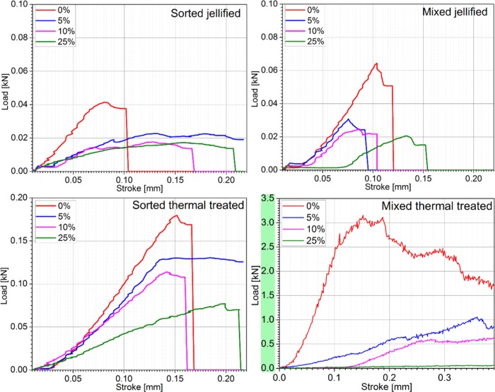
The load–stroke curves of jellified and thermal-treated (Figure 12) HA–starch specimens are presented in comparison with control samples (HA). Compression testing is performed only for 0, 5, 10, and 25 wt % starch concentrations. The HA samples with 50 wt % starch collapse under their own weight shortly after thermal treatment.
Figure 12.
Load–stroke curves for jellified and thermal-treated samples prepared with HA and starch. Starch content is expressed as weight percent on each curve.
Based on the ceramic particle size distribution and starch concentration, the load–stroke curves have different slopes, which suggest differences between load absorption and, implicitly, specimens’ microstructure. The HA green body (jellified—0 wt % starch) has a typical brittle behavior, without a plastic deformation. Material’s stiffness decreases with an increase in starch concentration. The jellified specimens prepared with sorted HA powders and 5–10 wt % starch exhibit a linear segment on the load displacement curve, which is explained by the pores compaction during compression. The jellified 25 wt % starch specimens exhibited a plastic/malleable behavior, with significant shortening of ∼1.4 mm.
Because the different particle size distribution leads to different packing configuration, the specimens prepared with mixed HA powders exhibit a higher strength due to particle arrangement, which increases the surface that may absorb mechanical loads. A decrease in ultimate strength is observed when the specimens with sorted HA powders are tested (41 vs 60 N—the ultimate strength of specimens prepared with mixed powders).
Thermal treatment induces a significant improvement in the mechanical properties of all of the tested specimens. Similar to jellified composites, the thermal-treated samples (ceramics from which starch is removed by thermal degradation) exhibit superior mechanical properties when prepared with mixed HA powders. An additional decrease in mechanical characteristics of the thermal-treated materials with an increase in starch concentration is also observed.
The compressive strength of jellified specimens (Figure 13a) decreases with an increase in starch concentration. A minor influence of HA particle size distribution is also observed, the specimens prepared with sorted powders (100–200 μm) having a slightly lower compression strength as compared to the ones prepared with mixed powders. This influence is due mainly to the better compaction and decreased porosity of jellified samples prepared with mixed HA powders.
Figure 13.
Compressive strength of (a) jellified and (b) thermal-treated HA and HA–starch samples. Starch content is expressed as weight percent for each sample.
Thermal treatment increases the compressive strength of the samples (Figure 13b). Maximum results are obtained for the specimen prepared with mixed HA powders without starch addition, which exhibit compressive strengths similar to cortical bone (170–200 MPa52). Significant differences are observed both due to starch concentration and particle size distribution. Because starch is removed after thermal treatment, the compressive strength of the specimens is attributed to the ceramic body densified by sintering.
Higher starch concentrations are equivalent to higher quantities of removed materials, which contributes to the decrease in compressive strength. However, this decrease is not significant for specimens prepared with sorted HA powders (100–200 μm) because all of the specimens exhibit a rather low compressive strength—10–20 MPa. Higher strength values, which significantly decrease with increase in starch concentration, are observed for the specimens prepared with mixed powders: the compressive strength decreases from 100 MPa for 5 wt % starch to 10 MPa for 25 wt % starch. After the thermal treatment, the spaces initially filled with starch are free, so the mechanical strength of thermal-treated bodies is ensured through particle junctions. Because the 100–200 μm particles geometry involves a large number of sharp edges (Figure 1f), the mechanical strength is ensured primarily through pointlike junctions, leading to overall poor mechanical properties that are not suitable for bone reconstruction.
3. Conclusions
Incorporation of starch as a consolidation and porogen agent in hydroxyapatite allowed the preparation of materials with suitable composition for clinical applications (materials’ suitability for medical applications still needs to be confirmed by in vitro evaluations).
The jellification of HA–starch materials occurred without significant structural modifications of the components. However, successful use of the rapid solidification abilities of starch is strictly dependent of the paste temperature during extrusion because starch jellification occurs in a limited temperature range (60–80 °C).
After the thermal treatment, starch was degraded and removed, leading to consolidated hydroxyapatite products with different levels of porosity corresponding to the quantity of incorporated starch and the HA particle size distribution (sorted or mixed powders). Starch incorporation was possible up to 25 wt % in the ceramic mixture; the samples prepared with higher concentrations collapsed immediately after the thermal treatment.
Because the mechanical testing of heat-treated samples prepared with sorted HA indicated poor mechanical properties for bone scaffolds, for next stages of robocasting ink development, the use of mixed powders with different particle sizes is recommended, which will ensure a homogeneous distribution of ceramic particles in the jellified samples. However, the compression strength of robocasted parts is expected to be significantly lower due to reduced surface of filaments and the net scaffold density, further influenced by the micro- and macroporosity.
4. Experimental Section
4.1. Samples Preparation
4.1.1. HA and Starch Powders
HA was prepared by thermal processing of bovine bone according to a previously described protocol.22,53 HA powder was obtained by milling the calcined bone in a planetary mill with agate bowl and balls54 and sorting the powders with standardized granulometric sieves.
Two HA powder batches were used in the experiments: (i) sorted powder—with 100–200 μm particle size; and (ii) mixed powder—prepared by mixing equal parts of powders with particles sizes <20, 20–40, 40–100, and 100–200 μm.
Each type of HA powder (sorted and mixed) was homogenized with 0–50 wt % food grade corn starch powder in the as-received state. Each batch of HA–starch powder was homogenized for 15 min using a tumbler mixer.
4.1.2. Jellified HA–Starch Samples
The HA–starch powders were homogenized with water in water/powder ratio of 1/4. Starch jellification was induced by heating the solutions at 70 ± 2 °C with continuous stirring. The jellified samples were formed by cold isostatic pressing at 25 MPa. Jellified samples were allowed to dry in atmospheric air for 240 h before testing.
4.1.3. Thermal-Treated HA–Starch Samples
The cylindrical jellified samples with different HA particle size distribution and different starch content were sintered in an electrical furnace in air atmosphere at 1200 °C for 4 h. The sintered bodies were stored at ambient conditions until testing.
For morphological and structural characterization, HA and starch powders were analyzed in their initial state. The jellified and thermal-treated HA–starch cylindrical samples were carefully fractured for analyzing the inner surfaces. For mechanical testing, jellified and heat-treated HA–starch specimens were machined to obtain smooth cylindrical samples (n = 5), with a final diameter of 10.0 ± 0.2 mm and a final height of 10.0 ± 2.1 mm.
4.2. Characterization
Thermal analyses of the as-prepared/as-received and mixed powders of HA and starch were performed with a DSC/TGA SDTQ600 equipment in the 20–1500 °C range. Experiments were performed in synthetic air, using alumina crucibles, and samples of ∼20 mg. The gas flow rate was 25 mL/min, and the heating rate was 10 °C/min.
Morphological characterization of the precursor powders, jellified, and thermal-treated ceramic bodies with different starch additions was performed by scanning electron microscopy (SEM) using a Philips ESEM 30 equipment in the low-vacuum mode at 0.7 mbar pressure. The samples were imaged without any coating or preparation.
The crystalline status of the materials was investigated with a Bruker D8 Advance X-ray difractometer, with Cu Kα (λ = 1.5418 Å) radiation, using a high efficiency linear detector of Lynx Eye type. The films were scanned in the angular range of 2θ = 9–50°, with a step size of 0.02° and 2 s acquisition time per step.
Fourier transform infrared (FTIR) spectroscopy was used for analyzing the functional groups present in the samples. The analyses were performed with a PerkinElmer BX Spectrum spectrometer, in attenuated total reflection mode using a Pike-MIRacle diamond head of 1.8 mm diameter. The spectra were recorded in the range 530–4000 cm–1 at a resolution of 4 cm–1, with a total of 128 scans per experiment.
Compression testing was performed with a Walter+Bai LSB300 universal testing machine with a 300 kN load cell. The machine cross head speed was set to 1 mm/min with data acquisition at 0.05 s.
Acknowledgments
This work was supported by a grant of the Romanian National Authority for Scientific Research and Innovation, CNCS—UEFISCDI, project number PN-III-P2-2.1-PED-2016-0892.
The authors declare no competing financial interest.
References
- Studart A. R.; et al. Processing routes to macroporous ceramics: a review. J. Am. Ceram. Soc. 2006, 89, 1771–1789. 10.1111/j.1551-2916.2006.01044.x. [DOI] [Google Scholar]
- Dorozhkin S. V. Calcium orthophosphates: occurrence, properties, biomineralization, pathological calcification and biomimetic applications. Biomatter 2011, 1, 121–164. 10.4161/biom.18790. [DOI] [PMC free article] [PubMed] [Google Scholar]
- Butscher A.; et al. Structural and material approaches to bone tissue engineering in powder-based three-dimensional printing. Acta Biomater. 2011, 7, 907–920. 10.1016/j.actbio.2010.09.039. [DOI] [PubMed] [Google Scholar]
- Cesarano J. III; King B. H.; Denham H.. Recent Developments in Robocasting of Ceramics and Multimaterial Deposition; Sandia National Laboratories: Albuquerque, NM, 1998. [Google Scholar]
- Franchin G.; et al. Direct ink writing of geopolymeric inks. J. Eur. Ceram. Soc. 2017, 37, 2481–2489. 10.1016/j.jeurceramsoc.2017.01.030. [DOI] [Google Scholar]
- Marques C. F.; et al. Biphasic calcium phosphate scaffolds fabricated by direct write assembly: Mechanical, anti-microbial and osteoblastic properties. J. Eur. Ceram. Soc. 2017, 37, 359–368. 10.1016/j.jeurceramsoc.2016.08.018. [DOI] [Google Scholar]
- Lewis J. A. Direct-write assembly of ceramics from colloidal inks. Curr. Opin. Solid State Mater. Sci. 2002, 6, 245–250. 10.1016/S1359-0286(02)00031-1. [DOI] [Google Scholar]
- de Hazan Y.; et al. Robotic deposition of 3d nanocomposite and ceramic fiber architectures via UV curable colloidal inks. J. Eur. Ceram. Soc. 2012, 32, 1187–1198. 10.1016/j.jeurceramsoc.2011.12.007. [DOI] [Google Scholar]
- Hoelzle D. J.; Alleyne A. G.; Johnson A. J. W. Micro-robotic deposition guidelines by a design of experiments approach to maximize fabrication reliability for the bone scaffold application. Acta Biomater. 2008, 4, 897–912. 10.1016/j.actbio.2008.02.018. [DOI] [PubMed] [Google Scholar]
- Feilden E.; et al. Robocasting of structural ceramic parts with hydrogel inks. J. Eur. Ceram. Soc. 2016, 36, 2525–2533. 10.1016/j.jeurceramsoc.2016.03.001. [DOI] [Google Scholar]
- Butscher A.; et al. Printability of calcium phosphate powders for three-dimensional printing of tissue engineering scaffolds. Acta Biomater. 2012, 8, 373–385. 10.1016/j.actbio.2011.08.027. [DOI] [PubMed] [Google Scholar]
- Gamelas J. A. F.; Martins A. G. Surface properties of carbonated and non-carbonated hydroxyapatites obtained after bone calcination at different temperatures. Colloids Surf., A 2015, 478, 62–70. 10.1016/j.colsurfa.2015.03.044. [DOI] [Google Scholar]
- Michna S.; Wu W.; Lewis J. A. Concentrated hydroxyapatite inks for direct-write assembly of 3-D periodic scaffolds. Biomaterials 2005, 26, 5632–5639. 10.1016/j.biomaterials.2005.02.040. [DOI] [PubMed] [Google Scholar]
- Silva L.et al. In Characterization of Hydroxyapatite Scaffold Using Corn Starch as Porous Agent, Proceedings of the 21st Brazilian Congress of Mechanical Engineering (COBEM 2011), Natal, RN, Brazil, Oct 24–28, 2011.
- Yang L.; et al. Preparation of porous hydroxyapatite ceramics with starch additives. Trans. Nonferrous Met. Soc. China 2005, 15, 257–260. [Google Scholar]
- Lyckfeldt O.; Ferreira J. M. F. Processing of porous ceramics by ‘starch consolidation’. J. Eur. Ceram. Soc. 1998, 18, 131–140. 10.1016/S0955-2219(97)00101-5. [DOI] [Google Scholar]
- Rodríguez-Lorenzo L. M.; Vallet-Regí M.; Ferreira J. M. F. Fabrication of porous hydroxyapatite bodies by a new direct consolidation method: starch consolidation. J. Biomed. Mater. Res. 2002, 60, 232–240. 10.1002/jbm.10036. [DOI] [PubMed] [Google Scholar]
- Xie F.; et al. Advanced Nano-biocomposites Based on Starch. Polysaccharides 2015, 1467–1553. 10.1007/978-3-319-16298-0_50. [DOI] [Google Scholar]
- Yu L.; Christie G. Measurement of starch thermal transitions using differential scanning calorimetry. Carbohydr. Polym. 2001, 46, 179–184. 10.1016/S0144-8617(00)00301-5. [DOI] [Google Scholar]
- Hoffmann B.; et al. A new biodegradable bone wax substitute with the potential to be used as a bone filling material. J. Mater. Chem. 2007, 17, 4028–4033. 10.1039/b707992n. [DOI] [Google Scholar]
- Mondal S.; et al. Studies on processing and characterization of hydroxyapatite biomaterials from different bio wastes. J. Miner. Mater. Charact. Eng. 2012, 11, 55–67. 10.4236/jmmce.2012.111005. [DOI] [Google Scholar]
- Miculescu F.; et al. Cortical bone as resource for producing biomimetic materials for clinical use. Dig. J. Nanomater. Biostruct. 2012, 7, 1667–1677. [Google Scholar]
- Chen L.; et al. Development of a new Injectable Calcium Phosphate Cement that contains modified starch. Key Eng. Mater. 2007, 843. 10.4028/0-87849-422-7.843. [DOI] [Google Scholar]
- Kaseem M.; Hamad K.; Deri F. Thermoplastic starch blends: A review of recent works. Polym. Sci., Ser. A 2012, 54, 165–176. 10.1134/S0965545X1202006X. [DOI] [Google Scholar]
- Kundu B.; et al. Development of porous HAp and β-TCP scaffolds by starch consolidation with foaming method and drug-chitosan bilayered scaffold based drug delivery system. J. Mater. Sci.: Mater. Med. 2010, 21, 2955–2969. 10.1007/s10856-010-4127-0. [DOI] [PubMed] [Google Scholar]
- ISO 13779-1. Implants for Surgery – Hydroxyapatite, Part 1: Ceramic Hydroxyapatite; International Organization for Standardization: Geneva, Switzerland, 2008. [Google Scholar]
- ISO 13779-2. Implants for Surgery – Hydroxyapatite, Part 2: Coatings of Hydroxyapatite; International Organization for Standardization: Geneva, Switzerland, 2008. [Google Scholar]
- Liao C.-J.; et al. Thermal decomposition and reconstitution of hydroxyapatite in air atmosphere. Biomaterials 1999, 20, 1807–1813. 10.1016/S0142-9612(99)00076-9. [DOI] [PubMed] [Google Scholar]
- Muralithran G.; Ramesh S. The effects of sintering temperature on the properties of hydroxyapatite. Ceram. Int. 2000, 26, 221–230. 10.1016/S0272-8842(99)00046-2. [DOI] [Google Scholar]
- Zhou J.; et al. High temperature characteristics of synthetic hydroxyapatite. J. Mater. Sci.: Mater. Med. 1993, 4, 83–85. 10.1007/BF00122983. [DOI] [Google Scholar]
- Wu J.-M.; Yeh T.-S. Sintering of hydroxylapatite–zirconia composite materials. J. Mater. Sci. 1988, 23, 3771–3777. 10.1007/BF00540526. [DOI] [Google Scholar]
- Ou S.-F.; Chiou S.-Y.; Ou K.-L. Phase transformation on hydroxyapatite decomposition. Ceram. Int. 2013, 39, 3809–3816. 10.1016/j.ceramint.2012.10.221. [DOI] [Google Scholar]
- Kim H.; et al. Control of phase composition in hydroxyapatite/tetracalcium phosphate biphasic thin coatings for biomedical applications. J. Mater. Sci.: Mater. Med. 2005, 16, 961–966. 10.1007/s10856-005-4430-3. [DOI] [PMC free article] [PubMed] [Google Scholar]
- Welch J. H.; Gutt W. High-temperature studies of system calcium oxide–phosphorus pentoxide. J. Chem. Soc. 1961, 4442–4444. 10.1039/JR9610004442. [DOI] [Google Scholar]
- Sung Y.-M.; Lee J.-C.; Yang J.-W. Crystallization and sintering characteristics of chemically precipitated hydroxyapatite nanopowder. J. Cryst. Growth 2004, 262, 467–472. 10.1016/j.jcrysgro.2003.10.001. [DOI] [Google Scholar]
- Marcelo T. M.; et al. Microstructural characterization and interactions in Ti- and TiH2-hydroxyapatite vacuum sintered composites. Mater. Res. 2006, 9, 65–71. 10.1590/S1516-14392006000100013. [DOI] [Google Scholar]
- Markovic M.; Fowler B. O.; Tung M. S. Preparation and comprehensive characterization of a calcium hydroxyapatite reference material. J. Res. Natl. Inst. Stand. Technol. 2004, 109, 553–568. 10.6028/jres.109.042. [DOI] [PMC free article] [PubMed] [Google Scholar]
- Heimann R. B.; Lehmann H. D.. Bioceramic Coatings for Medical Implants: Trends and Techniques; John Wiley & Sons, 2015. [Google Scholar]
- Sima L. E.; et al. Differentiation of mesenchymal stem cells onto highly adherent radio frequency-sputtered carbonated hydroxylapatite thin films. J. Biomed. Mater. Res., Part A 2010, 95A, 1203–1214. 10.1002/jbm.a.32947. [DOI] [PubMed] [Google Scholar]
- Uribe A. R.Fundamentals and Characterization of Fungally Modified Polysaccharides for the Production of Bio-plastics; University of Toronto, 2010. [Google Scholar]
- Zeng J.; et al. Comparison of A and B starch granules from three wheat varieties. Molecules 2011, 16, 10570–10591. 10.3390/molecules161210570. [DOI] [PMC free article] [PubMed] [Google Scholar]
- Galat A. Study of the Raman scattering and infrared absorption spectra of branched polysaccharides. Acta Biochim. Pol. 1980, 27, 135–142. [PubMed] [Google Scholar]
- Duta L.; et al. Novel doped hydroxyapatite thin films obtained by pulsed laser deposition. Appl. Surf. Sci. 2013, 265, 41–49. 10.1016/j.apsusc.2012.10.077. [DOI] [Google Scholar]
- Mihailescu N.; et al. Structural, compositional, mechanical characterization and biological assessment of bovine-derived hydroxyapatite coatings reinforced with MgF2 or MgO for implants functionalization. Mater. Sci. Eng., C 2016, 59, 863–874. 10.1016/j.msec.2015.10.078. [DOI] [PubMed] [Google Scholar]
- Landi E.; et al. Carbonated hydroxyapatite as bone substitute. J. Eur. Ceram. Soc. 2003, 23, 2931–2937. 10.1016/S0955-2219(03)00304-2. [DOI] [Google Scholar]
- Rey C.; et al. The carbonate environment in bone mineral: a resolution-enhanced Fourier transform infrared spectroscopy study. Calcif. Tissue Int. 1989, 45, 157–164. 10.1007/BF02556059. [DOI] [PubMed] [Google Scholar]
- Gibson I. R.; Bonfield W. Novel synthesis and characterization of an AB-type carbonate-substituted hydroxyapatite. J. Biomed. Mater. Res. 2002, 59, 697–708. 10.1002/jbm.10044. [DOI] [PubMed] [Google Scholar]
- Miculescu F.; et al. Progress in Hydroxyapatite–Starch Based Sustainable Biomaterials for Biomedical Bone Substitution Applications. ACS Sustainable Chem. Eng. 2017, 5, 8491–8512. 10.1021/acssuschemeng.7b02314. [DOI] [Google Scholar]
- Ishikawa T.; Wakamura M.; Kondo S. Surface characterization of calcium hydroxylapatite by Fourier transform infrared spectroscopy. Langmuir 1989, 5, 140–144. 10.1021/la00085a025. [DOI] [Google Scholar]
- Loy C. W.; et al. Effects of Calcination on the Crystallography and Nonbiogenic Aragonite Formation of Ark Clam Shell under Ambient Condition. Adv. Mater. Sci. Eng. 2016, 2016, 2914368 10.1155/2016/2914368. [DOI] [Google Scholar]
- Hayashizaki J.; et al. Preparation of Hydroxyapatite Fiber by using Alginate and its Application to Bioceramics. Bioceramics 1994, 41–46. 10.1016/b978-0-08-042144-5.50010-8. [DOI] [Google Scholar]
- McNamara S. L.; et al. Silk as a biocohesive sacrificial binder in the fabrication of hydroxyapatite load bearing scaffolds. Biomaterials 2014, 35, 6941–6953. 10.1016/j.biomaterials.2014.05.013. [DOI] [PMC free article] [PubMed] [Google Scholar]
- Maidaniuc A.; et al. Effect of micron sized silver particles concentration on the adhesion induced by sintering and antibacterial properties of hydroxyapatite microcomposites. J. Adhes. Sci. Technol. 2016, 30, 1829–1841. 10.1080/01694243.2016.1163808. [DOI] [Google Scholar]
- Maazouz Y.; et al. Robocasting of biomimetic hydroxyapatite scaffolds using self-setting inks. J. Mater. Chem. B 2014, 2, 5378–5386. 10.1039/C4TB00438H. [DOI] [PubMed] [Google Scholar]


