Abstract
The distribution of electric fields within the electrochemical double layer depends on both the electrode and electrolyte in complex ways. These fields strongly influence chemical dynamics in the electrode-electrolyte interface, but cannot be measured directly with sub-molecular resolution. We report experimental capacitance measurements for aqueous interfaces of CO-terminated Pt(111). By comparing these measurements with first-principles density-functional theory (DFT) calculations, we infer microscopic field distributions and decompose contributions to the inverse capacitance from various spatial regions of the interface. We find that the CO is strongly electronically coupled to the Pt, and that most of the interfacial potential difference appears across the gap between the terminating O and water, and not across the CO molecule as previously hypothesized. This ‘gap capacitance' resulting from hydrophobic termination lowers the overall capacitance of the aqueous Pt-CO interface, and makes it less sensitive to electrolyte concentration compared to the bare metal.
Graphical abstract

Chemical processes at electrochemical interfaces are fundamentally important for a wide range of technological applications including chemical synthesis, corrosion prevention, energy conversion and energy storage.1–5 The mechanisms, kinetics and selectivity of these processes depend critically on the microscopic structure of the electrodeelectrolyte interface. The distribution of electric fields and potentials at this interface is particularly important because it determines the adsorption/desorption energetics of relevant chemical species and their charge states at the surface.4–6 The basis for understanding field distributions in electrochemical interfaces is the double layer model of electrochemical capacitance.7 The total capacitance decomposes into two capacitors in series: an ‘inner layer’ or Stern capacitance dependent on electrode-solvent-ion interactions, and the Gouy-Chapman capacitance from ionic contributions in the outer ‘diffuse’ layer.8
The double layer model of electrochemical interfaces has been tested extensively for bare-metal electrode surfaces,9,10 but its applicability to metal surfaces with adsorbates has not yet been investigated as thoroughly.11–13 Recent experiments using Stark tuning as a probe of the local electric fields of adsorbates find results in support of the double layer model.14–16 Metal surfaces terminated by a strongly-bonded rigid adsorbate are most suitable for fundamental studies of the structure of such an interface that include first-principles calculations because the electrode+adsorbate structure remains in a single configuration with a purely electronic response, and does not require thermodynamic averaging over rotational and flexional modes. CO-terminated Pt surfaces are particularly well characterized, with electrochemical capacitance measurements in a range of solvents including water, acetonitrile and ionic liquids.17–19 The classical double layer model for this system consists of an inner layer with a linear potential drop covering the CO adlayer and extending till the outer Helmholtz plane, assumed to be one radius of unsolvated electrolyte ion beyond the first water layer.17 Smith and White12 proposed an alternate model for electroactive films in which the potential drops linearly across a dielectric, and then decays rapidly in the electrolyte.
It is challenging to experimentally evaluate these models because the sub-molecular field distributions within the electrode, adlayer and electrolyte cannot be measured directly in experiment. Direct measurement of microscopic fields is possible using Stark shift spectroscopy, but with a resolution limited to the size of the vibrational chromophore molecule added to the surface. Additionally, the adsorbed Stark tuning probe itself changes the field distribution and the double layer. First-principles calculations can probe field distribution over sub-molecular length scales, with density-functional theory (DFT) providing the structure and electronic response of the electrode + adlayer, coupled to suitable solvation models that capture the response of the electrolyte.
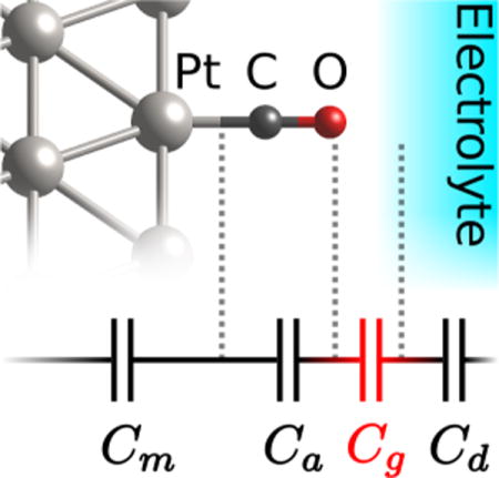
In this Letter, we combine experimental capacitance measurements with solvated DFT calculations to understand the aqueous Pt-CO interface in microscopic detail. We find good agreement between the DFT + continuum solvent predictions and experimental measurements for the total capacitance. The calculations additionally provide the atomic-scale variation of the potential across the metal, adlayer and electrolyte. We find two approximately-linear potential regions within the inner layer: a mostly flat potential region in the CO adlayer, and a far steeper potential profile in the gap between the terminal O and the start of the water. The ‘gap capacitance’ due to this second region contributes significantly to the lower capacitance and relative insensitivity to ionic concentrations, compared to metal electrodes, and illustrates the limitations of the classical inner/outer-layer division for hydrophobic adsorbates.20
The voltammetric experiments were performed in a three-electrode configuration using a Pt (111) bead (from icryst, www.icryst.com) as working electrode, a Pt wire as counter and a reversible hydrogen (RHE) as reference electrode, at room temperature. [Note: Certain commercial materials are identified in this paper to foster understanding. Such identification does not imply recommendation or endorsement by the National Institute of Standards and Technology, nor does it imply that the materials or equipment identified are necessarily the best available for the purpose.] The electrolyte solutions were prepared using different concentrations of HClO4 (70 %, Merck Suprapur) and ultrapure water (Merck Millipore, 18.2 MΩ cm). The electrochemical measurements were performed with the working electrode in hanging meniscus configuration and the potential was controlled with an Autolab PGSTAT302N potentiostat. The current density reported represents the measured current normalized to the electrochemical surface area of the working electrode. To ensure the proper surface ordering, the electrodes were prepared as previously described.23,24 Briefly, prior to each measurement, the crystals were flame-annealed and cooled to room temperature in an Ar:H2 (3:1) environment. Subsequently, the crystal was protected with a drop of water saturated in the same gas mixture and transferred to the electrochemical cell. All the experiments were performed by first acquiring a blank voltammogram of the Pt(111) in the electrolyte solution purged with Ar (6.0 Linde), to ensure the surface cleanliness and order. After recording the blank, CO (6.0 Linde) was purged in the solution for 2 minutes to ensure a full layer of CO on the electrode surface, and subsequently Ar was purged for 20 min through the electrolyte solution in order to remove all the CO from solution. During this process the electrode potential was kept at 0.1 V (vs RHE) to avoid CO oxidation. We only consider full CO coverage in the work as it is most reproducible experimentally and amenable for theoretical analysis of capacitance contributions due to its planar homogeneity. See Supporting Information for experimental voltammograms and details on the extraction of capacitance from the measurements.
Computationally, we follow the protocol previously established in Ref.25. Briefly, we perform plane-wave electronic DFT calculations in the JDFTx code,26 with the Perdew-Burke-Ernzerhof (PBE) exchange-correlation functional,27 ultrasoft pseudopotentials,28 and plane-wave kinetic energy cutoffs of 20 Eh (Hartrees) and 100 Eh for orbitals and charge densities respectively. We treat the bare and CO-terminated platinum surfaces with inversion-symmetric slabs with five Pt(111) layers, and use truncated Coulomb potentials29 to eliminate interactions with periodic images normal to the slab. We use a nonlinear continuum solvation model30 that captures nonlinearities in both the dielectric response of the solvent and ionic response of the electrolyte within a local-response approximation. We employ the original parametrization of this model based on solvation energies of organic solutes for the CO-terminated surface calculations, and the revised parametrization for metallic surfaces25 for the bare surface calculations. To evaluate capacitances and potential profiles, we calculate the change in electron number and electrostatic potential31 between a neutral DFT calculation and a grand canonical DFT calculation32 at a potential fixed 0.1 V below the neutral value. The solvation models used here have been carefully benchmarked for prediction of electrochemical properties,5,25 while equivalent treatment with ab initio molecular dynamics would require impractically large simulation cells to contain statistically meaningful numbers of ions in the electrolyte.32 Importantly, the key conclusions below relate to the electronic structure of the electrode calculated in DFT, and are therefore insensitive to the details of the solvation model.
Tables 1 and 2 list the total capacitance from these calculations and from the experimental measurements. The DFT calculated capacitance reduces from 26 μF/cm2 for the bare surface to 10 μF/cm2 for the CO-terminated surface. The DFT results are insensitive to the exchange-correlation functional and are in good agreement with experiment for the CO-terminated surface. For the Pt(111), we note that the experimental capacitance measurements are performed near the Hupd region, and include contributions from hydrogen adsorption onto the surface. When the experimental values are corrected for the hydrogen adsorption, they are considerably lower and closer to the values predicted from DFT calculations.21,22
Table 1.
The experimental double layer capacitances and standard deviations for bare Pt(111) and Pt(111) with adsorbed CO, extracted from measurements of the current density at 0.4 V at different scan rates. Below, ‘Hupd corrected' refers to correction of the capacitance for under-potential deposition of H as described in the Supporting Information.
Table 2.
DFT predictions of total capacitance of aqueous bare Pt(111) and Pt(111) with adsorbed CO, and the spatial decomposition of the DFT capacitances and inverse capacitances (from Fig. 1).
| System | Method | Capacitance [μF/cm2]
|
Inverse Capacitance [cm2/μF]
|
|||||||
|---|---|---|---|---|---|---|---|---|---|---|
| Total | Pt (Cm) |
CO (Ca) |
Gap (Cg) |
Diffuse (Cd) |
Pt |
CO |
Gap |
Diffuse |
||
|
| ||||||||||
| Pt | GGA | 27.5 | 784. | – | 32.0 | 259. | 0.0013 | – | 0.0312 | 0.0039 |
| LDA | 26.4 | 598. | – | 31.0 | 250. | 0.0017 | – | 0.0323 | 0.0040 | |
|
| ||||||||||
| Pt-CO | GGA | 9.7 | 228. | 39.5 | 14.3 | 252. | 0.0044 | 0.0253 | 0.0698 | 0.0040 |
| LDA | 9.4 | 185. | 39.2 | 14.0 | 235. | 0.0054 | 0.0255 | 0.0716 | 0.0043 | |
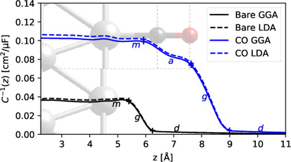
Next, to better understand the reason for the lowered capacitance for Pt-CO, we compare the spatial distribution of the DFT electrostatic potential for the CO-terminated and bare surfaces. Specifically, we define the inverse capacitance profile,
| (1) |
where is the electrostatic potential averaged along the directions parallel to the surface and N is the number of electrons in the DFT calculation. We calculate the derivative from the difference between calculations at the neutral potential V0 and a potential V1 = V0 — 0.1 V. With this definition, C−1(0) (with z = 0 inside the electrode) is the inverse of the total capacitance, and its spatial profile elucidates the contributions of each spatial region to the inverse capacitance (that combine in a series model).
Figure 1 shows the inverse capacitance profiles of the Pt and Pt-CO interfaces, compared between GGA and LDA DFT calculations. The potential is approximately constant inside the metal, which manifests as a flat C−1 profile up to the metal surface at z ≈ 5 Å. The bare Pt system has a lower inverse capacitance (higher total capacitance) in this flat region which extends till ≈ 1 Å away from the surface Pt atom. In contrast, the Pt-CO has a higher inverse capacitance (lower total capacitance), which reduces slowly across the CO, and then drops quickly past the terminal O atom. In both cases, most of the potential drop, and hence the C−1 change, occurs in the gap region between the outermost surface atom and the fluid. The results are mostly insensitive to the DFT functional, indicating that the spatially-resolved predictions are also relatively robust against DFT errors.
Figure 1.

Inverse capacitance for bare Pt(111) and Pt(111) terminated (atop) by CO. Dotted lines indicate the locations of C (gray) and O (red), as also shown by the atomic configuration in the background. Note that the center of the slab is at z = 0, and ‘+’s mark the points of maximum curvature for separating series capacitor regions, m (metal), a (adlayer, only for CO case), g (gap) and d (diffuse) (see Table. 2).
To further understand the drop in capacitance, we decompose the inverse capacitance across the entire interface into contributions from different spatial regions. We separate regions at the points of maximum magnitude of curvature in C—1(z) (points where the slope changes the most, i.e. where the induced charge density peaks), marked with ‘+’s in Fig. 1. Both the bare and CO-terminated systems exhibit a metal region ‘m’ at the left end and the diffuse region of the electrolyte ‘d’ at the right end. In the bare surface, these regions are separated by the gap region ‘g’, whereas for the CO-terminated surface, there is an additional region ‘a’ corresponding to the adlayer between the m and g regions. The total capacitance is given by the series capacitor model, , where is present only for the CO-terminated case.
Table 2 shows the separation of the total (inverse) capacitance into these spatial contributions. For both the bare and CO-terminated systems in 1 M (mol/L) aqueous electrolyte, the metal and diffuse inverse-capacitance contributions are negligible; the diffuse contribution will become more important at lower ionic concentrations near the potential of zero charge as usual within the Gouy-Chapman-Stern theory.7 Importantly, note that for the COterminated Pt surface, the series capacitance is dominated by the gap region, Cg ≈ 14 μF/cm2, rather than by the adlayer, Ca ≈ 40 μF/cm2 (lower capacitance dominates in series). Also note that this gap region capacitance for the CO-terminated surface is much smaller than that of the bare surface, Ca ≈ 30 μF/cm2. This suggests that the total capacitance of the Pt-CO interface is low because the surface repels solvent, rather than because the capacitance of the Pt-CO itself is low with the CO adlayer acting as an insulating spacer as previously suggested.17
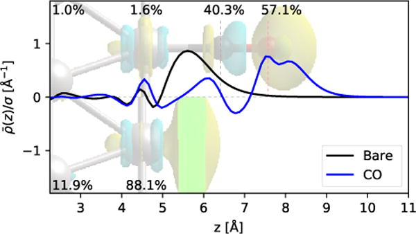
In fact, the CO adlayer appears to act more like an extension of the metal, as shown by the spatial distribution of the induced charge density in Fig. 2 (the planarly averaged charge density is normalized by the total surface charge density σ induced on the surface). For the bare metal, the surface charge density is mostly located in a sheet about 1 Å past the surface Pt atom. In the CO-terminated case, this sheet is replaced by a dipolar distribution on the C atom, followed by most of the surface charge appearing on the O atom and extending 0.5 Å to1 Å beyond it. This illustrates that the induced surface charge is migrating to the end of the carbon monoxide layer, supporting the fact the Pt-CO is insulated after, rather than by, the CO layer.
Figure 2.

Spatial profile of the planarly averaged induced electronic charge density in bare and CO-terminated Pt surfaces, with an isodensity surface of the induced charge distribution shown in the background image. The labels indicate the fraction of the induced charge in the neighborhood of each atom, calculated using Bader analysis, to the total induced charge on the surface.
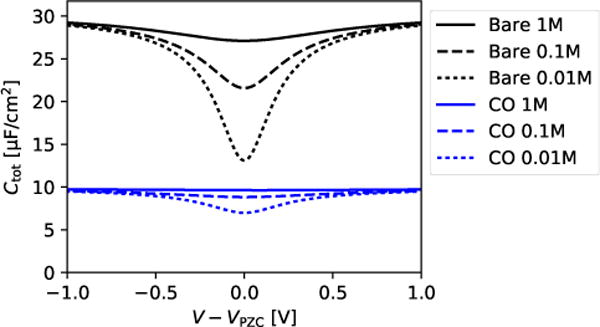
The dominance of the gap capacitance is unsurprising considering that the dielectric constant of the vacuum region is considerably lower than the dielectric constant of the surrounding regions. Even small gaps between the surface and the solvent result in large drops in potential, which predominates for hydrophobic surfaces such as the the COterminated Pt surface. Importantly, the induced charge migration to the end of the CO is entirely due to the electronic structure of the metal electrode and adlayer, and not the solvent. For this reason, the details of the solvation model do not matter beyond providing a diffuse capacitance and total capacitance of the overall correct magnitude. We chose 1 M electrolyte for the solvated DFT calculations because the fluid capacitance is large and contributes negligibly to the total series capacitance. Replacing the Cd ≈ 250 μF/cm2 (Table 2) with the Gouy-Chapman-Stern model results in the ionic concentration and potential dependent capacitance prediction shown in Fig. 3, for potentials above and below the potential of zero charge of each surface. The Pt-CO capacitance is expected to exhibit much smaller variations with ionic concentration and potential because it is dominated by the gap capacitance which is insensitive to these parameters. Experimentally, the capacitance variation with ionic strength is also quite low, and less than the experimental error. However, this may also be due to the potential difference between the potential of zero charge of the Pt-CO33 and the potential at which the capacitance is measured.
Figure 3.

Capacitance as a function of electrolyte ionic strength, with the Gouy-Chapman-Stern estimate of the diffuse capacitance, in series with the Cm, Ca, and Cg capacitance contributions from Table 2 for bare Pt and Pt-CO.
In conclusion, we find the low capacitance of the Pt-CO interface is primarily a result of the gap capacitance that occurs between the oxygen of the CO, and the solvent. The CO, strongly electronically-coupled to the Pt, acts as an extension of the metal, with most of the change in charge with potential occurring at the oxygen atom. Additionally, the CO capacitance is expected to be more insensitive than the bare Pt surface to the ionic strength of the electrolyte, as predicted from the Gouy-Chapman-Stern diffuse capacitance, coupled with the DFT-predicted Cm, Ca, and Cg capacitance terms.
Supplementary Material
Acknowledgments
RS acknowledges start-up funding from the Department of Materials Science and Engineering at Rensselaer Polytechnic Institute. Calculations were performed on the BlueGene/Q supercomputer in the Center for Computational Innovations (CCI) at Rensselaer Polytechnic Institute.
Footnotes
Supporting Information. Experimental voltammograms and details on extracting electrochemical capacitance from these measurements.
References
- 1.Taylor C, Chandra A, Vera J, Sridhar N. Multiphysics Modelling, Quantum Chemistry and Risk Analysis for Corrosion Inhibitor Design and Lifetime Prediction. Faraday Discuss. 2015;180:459–477. doi: 10.1039/c4fd00220b. [DOI] [PubMed] [Google Scholar]
- 2.Jaber-Ansari L, Puntambekar K, Kim S, Aykol M, Luo L, Wu J, Myers B, Iddir H, Russell J, Saldana S, et al. Suppressing Manganese Dissolution from Lithium Manganese Oxide Spinel Cathodes with Single-Layer Graphene. Adv Energy Mater. 2015;5:1500646. [Google Scholar]
- 3.Hori Y, Murata A, Takahashi R. Formation of Hydrocarbons in the Electrochemical Reduction of Carbon Dioxide at a Copper Electrode in Aqueous Solution. J Chem Soc Faraday Trans 1. 1989;85:2309–2326. [Google Scholar]
- 4.Chen L, Urushihara M, Chan K, Norskov J. Electric Field Effects in Electrochemical CO2 Reduction. ACS Catal. 2016;6:7133–7139. [Google Scholar]
- 5.Xiao H, Cheng T, Goddard WA, III, Sundararaman R. Mechanistic Explanation of the pH Dependence and Onset Potentials for Hydrocarbon Products from Electrochemical Reduction of CO on Cu(111) J Am Chem Soc. 2016;138:483–486. doi: 10.1021/jacs.5b11390. [DOI] [PubMed] [Google Scholar]
- 6.Schwarz KA, Sundararaman R, Moffat TP, Allison T. Formic Acid Oxidation on Platinum: a Simple Mechanistic Study. Phys Chem Chem Phys. 2015;17:20805–20813. doi: 10.1039/c5cp03045e. [DOI] [PubMed] [Google Scholar]
- 7.Bard A, Faulkner L. Electrochemical Methods: Fundamentals and Applications. 2nd. John Wiley and Sons, Inc; Hoboken, NJ: 2001. [Google Scholar]
- 8.Stern O. The Theory of the Electrolytic Double Shift. Z Elektrochem Angew Phys Chem. 1924;30:508–516. [Google Scholar]
- 9.Parsons R, Zobel F. The Interphase between Mercury and Aqueous Sodium Dihydrogen Phosphate. J Electroanal Chem. 1965;9:333–348. [Google Scholar]
- 10.Schmickler W, Henderson D. The Interphase between Jellium and a Hard Sphere Electrolyte: Capacity-Charge Characteristics and Dipole Potentials. J Chem Phys. 1986;85:1650–1657. [Google Scholar]
- 11.Crispin X, Geskin V, Bureau C, Lazzaroni R, Schmickler W, Bredas J. A Density Functional Model for Tuning the Charge Ttransfer between a Transition Metal Electrode and a Chemisorbed Molecule via the Electrode Potential. J Chem Phys. 2001;115:10493–10499. [Google Scholar]
- 12.Smith CP, White HS. Theory of the Interfacial Potential Distribution and Reversible Voltammetric Response of Electrodes Coated with Electroactive Molecular Films. Anal Chem. 1992;64:2398–2405. doi: 10.1021/ac00044a017. [DOI] [PubMed] [Google Scholar]
- 13.Dunwell M, Wang J, Yan Y, Xu B. Surface Enhanced Spectroscopic Investigations of Adsorption of Cations on Electrochemical Interfaces. Phys Chem Chem Phys. 2017;19:971–975. doi: 10.1039/c6cp07207k. [DOI] [PubMed] [Google Scholar]
- 14.Ge A, Videla P, Lee G, Rudshteyn B, Song J, Kubiak C, Batista V, Lian T. Interfacial Structure and Electric Field Probed by in Situ Electrochemical Vibrational Stark Effect Spectroscopy and Computational Modeling. J Phys Chem C. 2017;121:18674–18682. [Google Scholar]
- 15.Patrow J, Sorenson S, Dawlaty J. Direct Spectroscopic Measurement of Interfacial Electric Fields near an Electrode under Polarizing or Current-Carrying Conditions. J Phys Chem C. 2017;121:11585–11592. [Google Scholar]
- 16.Sorenson S, Patrow J, Dawlaty J. Solvation Reaction Field at the Interface Measured by Vibrational Sum Frequency Generation Spectroscopy. J Am Chem Soc. 2017;139:2369–2378. doi: 10.1021/jacs.6b11940. [DOI] [PubMed] [Google Scholar]
- 17.Roth JD, Weaver MJ. Role of the Double-Layer Cation on the Potential-Dependent Stretching Frequencies and Binding Geometries of Carbon Monoxide at Platinum-Nonaqueous Interfaces. Langmuir. 1992;8:1451–1458. [Google Scholar]
- 18.Baldelli S. Probing Electric Fields at the Ionic Liquid-Electrode Interface Using Sum Frequency Generation Spectroscopy and Electrochemistry. J Phys Chem B. 2005;109:113049–13051. doi: 10.1021/jp052913r. [DOI] [PubMed] [Google Scholar]
- 19.Wasileski S, Koper M, Weaver M. Field-Dependent Electrode–Chemisorbate Bonding:Sensitivity of Vibrational Stark Effect and Binding Energetics to Nature of Surface Coordination. J Am Chem Soc. 2002;124:2796–2805. doi: 10.1021/ja012200w. [DOI] [PubMed] [Google Scholar]
- 20.Pham TA, Lee D, Schwegler E, Galli G. Interfacial Effects on the Band Edges of Functionalized Si Surfaces in Liquid Water. J Am Chem Soc. 2014;136:17071–17077. doi: 10.1021/ja5079865. [DOI] [PubMed] [Google Scholar]
- 21.Pajkossy D, Kolb D. Double Layer Capacitance of Pt(111) Single Crystal Electrodes. Electrochim Acta. 2001;46:3063–3071. [Google Scholar]
- 22.Garcia-Araez N, Climent V, Herrero E, Feliu JM, Lipkowski J. Thermodynamic Approach to the Double Layer Capacity of a Pt(111) Electrode in Perchloric Acid Solutions. Electrochim Acta. 2006;51:3787–3793. [Google Scholar]
- 23.Clavilier J, Actii KE, Petit M, Rodes A, Zamakhchari MA. Electrochemical Monitoring of the Thermal Reordering of Platinum Single-Crystal Surfaces after Metallographic Polishing from the Early Stage to the Equilibrium Surfaces. J Electroanal Chem Interfacial Electrochem. 1990;295:333–356. [Google Scholar]
- 24.Climent V, Feliu JM. Thirty Years of Platinum Single Crystal Electrochemistry. J Solid State Electrochem. 2011;15:1297–1315. [Google Scholar]
- 25.Sundararaman R, Schwarz K. Evaluating Continuum Solvation Models for the Electrode-Electrolyte Interface: Challenges and Strategies for Improvement. J Chem Phys. 2017;146:084111. doi: 10.1063/1.4976971. [DOI] [PMC free article] [PubMed] [Google Scholar]
- 26.Sundararaman R, Letchworth-Weaver K, Schwarz KA, Gunceler D, Ozhabes Y, Arias TA. JDFTx: Software for Joint Density-Functional Theory. 2017 doi: 10.1016/j.softx.2017.10.006. arXiv.1708.03621. [DOI] [PMC free article] [PubMed] [Google Scholar]
- 27.Perdew JP, Burke K, Ernzerhof M. Generalized Gradient Approximation Made Simple. Phys Rev Lett. 1996;77:3865–3868. doi: 10.1103/PhysRevLett.77.3865. [DOI] [PubMed] [Google Scholar]
- 28.Garrity KF, Bennett JW, Rabe K, Vanderbilt D. Pseudopotentials for High-throughput DFT Calculations. Comput Mater Sci. 2014;81:446–452. [Google Scholar]
- 29.Sundararaman R, Arias T. Ideal Regularization of the Coulomb Singularity in Exact Exchange by Wigner-Seitz Truncated Interactions: Towards Chemical Accuracy in Non-trivial Systems. Phys Rev B. 2013;87:165122. [Google Scholar]
- 30.Gunceler D, Letchworth-Weaver K, Sundararaman R, Schwarz KA, Arias TA. The Importance of Nonlinear Fluid Response in Joint Density-Functional Theory Studies of Battery Systems. Modell and Simul Mat Sci Eng. 2013;21:074005. [Google Scholar]
- 31.Sundararaman R, Ping Y. First-principles Electrostatic Potentials for Reliable Alignment at Interfaces and Defects. J Chem Phys. 2017;146:104109. doi: 10.1063/1.4978238. [DOI] [PubMed] [Google Scholar]
- 32.Sundararaman R, Goddard WA, III, Arias TA. Grand Canonical Electronic Density-Functional Theory: Algorithms and Applications to Electrochemistry. J Chem Phys. 2017;146:114104. doi: 10.1063/1.4978411. [DOI] [PubMed] [Google Scholar]
- 33.Cuesta A. Measurement of the Surface Charge Density of CO-saturated Pt(111) Electrodes as a Function of Potential: the Potential of Zero Charge of Pt(111) Surf Sci. 2004;572:11–22. [Google Scholar]
Associated Data
This section collects any data citations, data availability statements, or supplementary materials included in this article.


