

Abstract
Shape memory polymer (SMP) foams have been developed for use in neurovascular occlusion applications. These materials are predominantly polyurethanes that are known for their biocompatibility and tunable properties. However, these polymers inherently lack X-ray visibility, which is a significant challenge for their use as implantable materials. Herein, low density, highly porous shape memory polyurethane foams were developed with tungsten nanoparticles dispersed into the foam matrix, at increasing concentrations, to serve as a radiopaque agent. Utilizing X-ray fluoroscopy sufficient visibility of the foams at small geometries was observed. Thermal characterization of the foams indicated altered thermal response and delayed foam actuation with increasing nanoparticle loading (because of restricted network mobility). Mechanical testing indicated decreased toughness and strength for higher loading because of disruption of the SMP matrix. Overall, filler addition imparted x-ray visibility to the SMP foams and allowed for tuned control of the transition temperature and actuation kinetics for the material.
Keywords: nanocomposite, radiopacity, dispersion, aneurysm, glass transition temperature
INTRODUCTION
Polymers have been utilized as medical implants for the last 30 years with much success.[1,2] Some natural and synthetic polymers are known to be biocompatible, indicating their ability to perform with appropriate host response for biomedical applications.[1] These biocompatible polymers, commonly referred to as polymeric biomaterials, are known to have a wide range of applications because of their wide availability, ease of manufacturing, and tunable mechanical and thermal properties.[1,3] Some of the most common biomaterials include polyethylene (PE), polyurethane (PU), polytetrafluoroethylene (PTFE), polymethylmethacrylate (PMMA), poly(lactic acid) (PLA), and poly(glycolic acid) (PGA),[1,3] which currently have found uses as biodegradable sutures and fixation screws. While these materials can be fabricated into complex shapes and are available in a wide range of compositions, most tend to have low tensile strength and Young’s modulus for applications that require mechanical robustness, such as orthopedic implants.[1] Additionally, polymers have similar properties to that of soft tissue, limiting their radiological detectability.[1,4] Most polymeric materials lack radiopacity because their elements possess low electron density and low specific gravity.[2,5,6] Several steps have been taken to improve radiopacity of polymers by incorporating heavy-metal fillers as physical mixtures, attaching heavy-metal salts to the polymer backbone via chelation, and by covalently binding radiopaque elements to monomers prior to their polymerization.[2,5]
Radiopaque polymeric blends consisted of heavy metal fillers physically mixed into the polymer matrix thus imparting radiopacity to the whole system because of the high Z-element nature of the filler.[5] Most commonly used fillers for this technique include iodine, barium, bismuth, zircon, and tantalum.[2,6–10] While successful radiopacity was achieved, the composites generally suffered from reduced mechanical properties because of heterogeneous dispersion of the radiopaque filler from phase separation of metal fillers from resins.[2] This resulted in aggregate formation that ultimately caused crack formation and propagation in the polymer matrix leading to leakage of the radiopaque filler.[5]
Chithambara et al. synthesized radiopaque microspheres by dispersing tantalum within a polymer matrix synthesized using toluene diisocyanate and poly(tetramethylene glycol).[7] Their findings proved the microspheres to be radiopaque with potential as radiopaque embolization agents.[7] However, higher filler loadings resulted in greater aggregates within the polymer, inducing particle size variability.[7]
Barium has also been used to impart radiopaque properties for a variety of medical devices, including denture materials.[11–13] In one study, barium fluoride (BaF2), at 30 wt%, was used to develop denture material because of its satisfactory radiopacity and minimal discoloration of the material overall.[11] However, BaF2 leaching occurred within seven days causing the filler to infiltrate the surrounding tissue. This induced toxicity and altered the mechanical properties of the material.[11]
Radiopaque polymer salt complexes were developed to improve homogeneity and reduce gradual filler leaching.[5,14] A heavy metal salt was complexed to an appropriate polymer ligand via chelation resulting in a homogenous system with polymeric and ionic character.[2] The polymers used for this technique were ionic, meaning they had a charged polar section to bind to cations and a non-polar section which would allow solubilization in non-polar media.[5] Polymer salt complexes were advantageous because they result in limited heavy metal release and constant radiopacity because of entrapment of the salt in a complex network.[14] However, the binding of the salt to the polymer ligand was a result of non-covalent interactions which could easily be disrupted in acidic aqueous conditions, similar to some physiological conditions.[5] Additionally, the halogenated functional groups in these systems may degrade via hydrolysis and result in potentially toxic leachables.[5]
Radiopaque polymerized monomers were also used to impart radiopacity to polymers by synthesizing radiopaque monomers that could covalently be incorporated into the polymer backbone.[6,15,16] This technique resulted in homogenous, non-leachable materials that retained similar mechanical properties to that of the non-radiopaque parent polymer.[2,5] However, a major disadvantage of utilizing these systems is the high production cost, which may not be practical for all medical applications.[5]
In this work, the authors developed radiopaque composite materials using shape memory polymers (SMPs) for their use as biomedical implants. Thermally actuated shape memory polymers are a special class of materials that are capable of switching between a primary and a secondary shape upon a heat stimulus.[17–21] These versatile materials are used for a wide range of applications such as biomaterials, textiles, and automotive.[22,23] Hasan et al. developed aliphatic polyurethane/urea SMP foams for embolic occlusion applications because of their ability to retain a programmed shape and passively actuate inside the body over a given time.[24] Previously synthesized SMP foams have proven to rapidly occlude aortic aneurysms and the resulting clot is stable up to 90 days.[25,26] These SMP foams can further be utilized for a neurovascular occlusion device because of their ultra-low density, which allows for the material to be crimped to a small geometry and delivered to the aneurysm via catheter.[26]
X-ray visualization of the device, however, is a challenge, because the polyurethane SMP material has a density similar to soft tissue and cannot be observed during x-ray fluoroscopy.[25] Therefore delivery of the foam to the aneurysm in a safe and reliable manner is a significant challenge, as guidance by x-ray contrast cannot be used. The purpose of this work was to introduce radiopacity to the foam using heavy metal nanoparticles, which can be incorporated into the polymer using physical mixing. Tungsten has been used as a radiopaque agent previously for embolic coils with much success.[25,27–30] Kampmann et al. studied tungsten biocompatibility in human subjects showing minimal inflammatory response invoked by the radiopaque coils.[27] Additionally, Peuster et al. evaluated in vitro cytotoxic effects of tungsten on various human cells. Their studies concluded that while tungsten may be elevated in the blood serum, there were no cytotoxic effects on the local tissue.[28]
Based on the established biocompatibility of tungsten, Rodriguez et al. synthesized SMP foams for embolic applications with tungsten microparticles to induce x-ray visualization and achieved sufficient opacity with foam geometries up to 6-mm diameter cylinders.[25] While the SMP microcomposites were visible under x-ray fluoroscopy, radiopacity was highly dependent on the diameter of the foam cylinders. Larger diameter cylinders would limit the accessibility of the embolic devices to peripheral blood vessels only therefore small geometry radiopaque materials need to be developed for neurovascular applications. Additionally, high filler loading disrupted foam synthesis. Previously, 4% by volume was the maximum tungsten loading that could be achieved with microparticles which would also require the use of large geometry foam cylinders for visualization. This study aims to increase filler loading by using nanoparticles, allowing for improved particle dispersion resulting in visualization of smaller geometry materials for neurovascular devices that require radiopacity through soft and hard tissue. The materials developed by Hasan et al. had optimal actuation profiles of 5 to 10 min for device delivery and served as the core chemistry for this research.
EXPERIMENTAL
N,N,N′,N′-Tetrakis(2-hydroxypropyl)ethylenediamine (HPED, 99%; Sigma-Aldrich Inc., St. Louis, MO), triethanolamine (TEA, 98%; Sigma-Aldrich Inc., St. Louis, MO), trimethyl-1,6-hexamethylene diisocyanate, 2,2,4- and 2,4,4- mixture (TMHDI, TCI America Inc., Portland, OR), DC 198 (Air Products and Chemicals, Inc., Allentown, PA), DC 5943 (Air Products and Chemicals, Inc., Allentown, PA), T-131 (Air Products and Chemicals, Inc. Allentown, PA), BL-22 (Air Products and Chemicals, Inc, Allentown, PA), Enovate 245fa Blowing Agent (Honeywell International, Inc., Houston, TX), 0.1 N hydrochloric acid (HCl) (Sigma-Aldrich Inc., St. Louis, MO), 2-propanol 99% (IPA) (VWR, Radnor, PA) and deionized (DI) water (>17 MΩ cm purity; Millipore water purifier system; Millipore Inc., Billerica, MA) were used as received. Tungsten nanoparticles (W, 99.95%, 40–60 nm) (US Research Nanomaterials Inc., Houston, TX) were dried for 12 hr, under vacuum, prior to foam synthesis.
SMP foam synthesis was conducted using the protocol described by Hasan et al. Isocyanate (NCO) pre-polymer was first synthesized and cured for 32 hr at 50°C. TMDHI comprised the NCO pre-polymer along with 35% of alcohols (HPED and TEA).[24] W nanoparticles (40–60 nm) were dispersed in the NCO pre-polymer, prior to foam blowing, at 4% to 11% by volume. Molar equivalent of the remaining hydroxyls was added to the hydroxyl (OH) pre-polymer. The resulting OH pre-polymer was combined with the NCO-W mixture, along with catalysts, surfactants, and Enovate.[24] The foam was cured at 90°C under vacuum at −10 mmHg for 10 min.[24] The SMP foam was allowed to cool to room temperature before further characterization.[24] Post-cure purification of the SMP included acid etching the nanocomposites using 0.1 N HCl for 2 hr followed by two 15-min sonication cycles in IPA. The SMP foams were then rinsed using reverse osmosis (RO) water using four 15-min sonication cycles. The purified foams were dried overnight at 55°C under vacuum. Table 1 shows the weight percent of each component used in foam blowing. Three foam batches were synthesized and characterized for duplicity. Foams with 11%W loading were not reproducible and therefore their thermo-mechanical properties were not characterized.
Table 1.
Composition of foams using 100% trimethylhexamethylene diisocyanate (TMHDI) for the isocyanate component of the urethane foam and increasing volume percent concentration of W nanoparticles. Three foam batches were synthesized and the average weight percent of the monomers and volume percent of tungsten nanoparticles was determined for all batches
| Composition | W (vol %) | TMHDI (wt%) | HPED (wt%) | TEA (wt%) | Water (wt%) | T-131 (wt%) | BL-22 (wt%) | DC 198 (wt%) | DC 5943 (wt%) | Enovate (PPH) |
|---|---|---|---|---|---|---|---|---|---|---|
| 100TMDHI 0%W | 0.00 ± 0 | 66.70 ± 0.1 | 17.11 ± 0.02 | 5.74 ± 0.01 | 2.35 ± 0 | 0.26 ± 0 | 0.65 ± 0 | 2.62 ± 0.1 | 4.59 ± 0.01 | 14.88 ± 0 |
| 100TMDHI 4%W | 4.00 ± 0.001 | 66.72 ± 0.03 | 17.10 ± 0.04 | 5.75 ± 0.03 | 2.35 ± 0.01 | 0.26 ± 0.01 | 0.65 ± 0.01 | 1.71 ± 1 | 5.45 ± 1 | 14.57 ± 2 |
| 100 TMHDI 5%W | 4.99 ± 0.002 | 66.69 ± 0.1 | 17.13 ± 0.02 | 5.74 ± 0 | 2.36 ± 0 | 0.26 ± 0 | 0.65 ± 0 | 2.56 ± 0.03 | 4.61 ± 0.1 | 14.55 ± 2 |
| 100 TMHDI 6%W | 5.99 ± 0.01 | 66.72 ± 0.04 | 17.12 ± 0.02 | 5.74 + 0 | 2.35 ± 0 | 0.26 ± 0.01 | 0.66 ± 0.01 | 2.55 ± 0.02 | 4.60 ± 0.04 | 14.55 ± 2 |
| 100 TMHDI 7%W | 6.99 ± 0.01 | 66.75 ± 0.04 | 17.12 ± 0.02 | 5.74 ± 0 | 2.34 ± 0.01 | 0.26 ± 0.01 | 0.65 ± 0.01 | 2.54 ± 0.02 | 4.60 ± 0.03 | 17.00 ± 0.1 |
| 100 TMHDI 8%W | 7.98 ± 0.01 | 66.71 ± 0.1 | 17.13 ± 0.03 | 5.74 ± 0.03 | 2.35 ± 0.01 | 0.26 ± 0.01 | 0.65 ± 0.01 | 2.54 ± 0 | 4.61 ± 0.01 | 16.98 ± 0.04 |
| 100 TMHDI 9%W | 8.98 ± 0.01 | 66.76 ± 0.1 | 17.12 ± 0 | 5.74 ± 0.03 | 2.35 ± 0.01 | 0.26 ± 0 | 0.64 ± 0 | 2.56 ± 0.02 | 4.58 ± 0.02 | 17.00 ± 0.04 |
| 100 TMHDI 10%W | 9.98 ± 0.01 | 66.73 ± 0.03 | 17.13 ± 0 | 5.74 ± 0.02 | 2.35 ± 0.01 | 0.26 ± 0 | 0.64 ± 0 | 2.55 ± 0.01 | 4.61 ± 0.02 | 16.99 ± 0.02 |
| 100 TMHDI 11%W | 10.97 | 66.72 | 17.11 | 5.74 | 2.36 | 0.25 | 0.65 | 2.60 | 4.58 | 17.00 |
Density and porosity
Density measurements were conducted on foam blocks acquired from the top, middle, and bottom section of the foam. Mass of the foam block was recorded and length, width, and height values were measured three times using a digital caliper. Porosity was calculated using eqn (1). Density of the non-porous neat polymer was calculated without accounting for foaming agents such as catalysts, surfactants, DI water, and Enovate.
| (1) |
Scanning electron microscopy (SEM) and pore sizes
Cell structure was determined by cutting thin slices of the bulk foam in the axial and transverse direction. The samples were mounted onto a stage and sputter coated for 60 sec at 20 mA with gold using Cressington Sputter Coater (Ted Pella, Inc., Redding, CA). The samples were then imaged using Joel NeoScope JCM-5000 Scanning Electron Microscope (Nikon Instruments, Inc., Melville, NY) at 10–13× magnification under high vacuum and 5–10-kV current. Pore sizes were calculated by measuring the cell diameter, using Image J software (NIH, Bethesda, MD), in the axial and transverse direction for each SEM image.
Transmission electron microscopy (TEM)
A small piece (2 mm × 4 mm) of the sample was cut and embedded in the flat mold with Polybed 812 (Polysciences, Inc., Warrington, PA) and polymerized at 60°C, overnight. The sample resin block was sectioned at room temperature, using Leica UC6 microtome (Leica Microsystems, Wetzlar, Germany) and DiATOME diamond knives (DiATOME, Hatfield, PA). Ultra-thin sections (70 nm) were examined by JEOL 1200EX II electron microscopy (Jeol, Peabody, MA).
X-ray imaging
An opacity frame was developed by mounting filler-loaded foam samples onto a clear polycarbonate sheet. Two millimeter foam cylinders were threaded over an 89-μm diameter nickel–titanium (Nitinol) wire (NDC, Fremont, CA). A Guglielmi Detachable Coil (GDC) (Boston Scientific, Marlborough, MA) used as the control for this experiment because it is a platinum coil which is considered the current gold standard for aneurysm treatment. The opacity frame was placed under a porcine head and imaged using a Philips Allura Xper FD 20 C-arm System (Koninklijke Philips N.V., Amsterdam, Netherlands) at 63 kV and 382 mA through soft and hard tissue. Images of the opacity frame were collected under porcine jaw and neck for evaluating foam visibility at multiple sites compared to the control.
X-ray density (XD)
X-ray images of the opacity frame were acquired on a Bruker In-Vivo Xtreme multimodal preclinical imaging system (Bruker BioSpin Corp., Billerica, MA) outfitted with a 4 MP back-thinned, back-illuminated 4MP CCD detector. X-rays were collected with an exposure time of 1.0 s, where the f-stop = 1.40, FOV = 153.0 mm, vertical and horizontal resolution = 377 ppi and X-ray energy = 45 KVP. Images were edited using Bruker molecular imaging software. The background was subtracted using an illumination correction reference. To quantify the x-ray density for each sample, a length of 0.50 cm was selected along each sample in the X-ray image as the region of interest. Greater than 70 pixels of X-ray density (XD) were taken within the region of interest for each foam utilizing Bruker Molecular Imaging Software (Bruker BioSpin Corp., Billerica, MA). From these measurements, a mean and standard deviation of the XD was calculated.
Differential scanning calorimetry (DSC)
The glass transition temperature (Tg) of the foams (n = 5) was determined under dry and wet conditions. For dry Tg, foam samples (3–8 mg) were used which were stored in a dry container with desiccant, prior to analysis. A Q-200 DSC (TA Instruments, Inc., New Castle, DE) was used to attain the thermogram for our foams. The first cycle consisted of decreasing the temperature to −40°C at 10°C min−1 and holding it isothermal for 2 min. The temperature was then increased to 120°C at 10° C min−1 and held isothermal for 2 min. In the second cycle, the temperature was reduced to −40°C at 10°C min−1, held isothermal for 2 min, and raised to 120°C at 10°C min−1. Tg was recorded from the second cycle based on the inflection point of the thermal transition curve using TA instruments software (TA Instruments, Inc., New Castle, DE). The aluminum tin was not vented during this step. For wet Tg, foam samples (3–8 mg) were submerged in RO water at 50°C for 5 min to allow full plasticization. After the samples were removed from water, they were pressed dry with Kim Wipes (Kimberly-Clark Professionals, Roswell, GA), weighed, and placed in an aluminum pan sealed with an aluminum lid that was vented. Q-200 DSC was used to cool the samples to −40°C, hold them isothermal for 2 min, and heat them to 80°C at 10°C min−1. TA instruments software (TA Instruments, Inc., New Castle, DE) was used to generate the thermogram and acquire the Tg, after water plasticization, using the average inflection point of the thermal transition.
Tensile testing
Uniaxial tensile loading tests were carried out using an Insight 30 Material Tester (MTS Systems Corporation, Eden Prairie, MN) at a constant strain rate of 5 mm/min at room temperature. Ten foam samples with (L = 25 mm, W = 15 mm, H = 3 mm) were cut from the bulk material. Wood tabs were secured on each end of the foam, using epoxy, to prevent sample deformation in the grips during testing. Tensile strength (kPa), Young’s modulus (kPa), toughness (J m−3), and strain at break (%) were determined per sample using the stress–strain curve.
Actuation studies
Cylindrical foam samples (n = 3) with a diameter of 2 mm and a height of 1 cm were cut. A 203.20-μm diameter nickel–titanium (Nitinol) wire (NDC, Fremont, CA) was inserted through the center of the sample along its length to serve as a stabilizer. The foam samples were radially compressed to their smallest possible diameter using ST 150-42 stent crimper (Machine Solutions, Flagstaff, AZ) by heating the material to 100°C, holding it isothermal for 15 min, and programming the foams to the crimped morphology. Initial foam diameter was measured and recorded for each sample using Image J software. The foams were placed in a water bath at 37°C, and images were taken at 30 sec, 1 min, and every minute thereafter till 15 min, followed by one image every 5 min thereafter till 30 min. Foam diameter was measured, at each time point, using Image J software. The foams were then placed in a 70°C RO water bath, removed after 20 min, and allowed to cool to room temperature. The final diameter of the samples was measured and recorded using Image J software. Percent volume recovery was calculated using eqn (2), and volume expansion was calculated using eqn (3).
| (2) |
| (3) |
RESULTS
Density and porosity
Foam density increased markedly, from 0.013 to 0.060 g cm−3, with greater W incorporation because of the added mass within the foam struts per block (Table 2). All compositions, however, maintained low densities, indicative of the foams retaining high surface area to volume ratios. SMP nanocomposites containing 10%W had significantly lower density than 9%W foams because of changes in pore sizes which are discussed in the next section. Neat polymer density also increased with W addition (Table 2), from 1.0 to 3.0 g cm−3, indicating the material became heavier with filler content without variation from foaming agents. Porosity calculations (Table 2) showed high porosity (>98%) for all compositions with low standard deviation, indicating cell uniformity throughout the bulk foam. These results confirm the development of lightweight foams with high surface area suitable for embolic occlusion devices.
Table 2.
Key physical and thermal properties of the SMP foam nanocomposites
| W (vol %) | ρfoam (g cm−3) | ρneat (g cm−3) | Porosity (%) | Dry Tg (°C) | Wet Tg (°C) | Volume recovery (%) | Volume expansion (x) |
|---|---|---|---|---|---|---|---|
| 0%W | 0.013 ± 0.001 | 1.0 ± 0.02 | 99 ± 0.1 | 58 ± 2 | 34 ± 1 | 108 ± 24 | 63 ± 14 |
| 4%W | 0.033 ± 0.004 | 1.8 ± 0.03 | 98 ± 0.2 | 63 ± 1 | 28 ± 1 | 82 ± 15 | 21 ± 4 |
| 5%W | 0.041 ± 0.000 | 2.0 ± 0.04 | 98 ± 0.0 | 65 ± 1 | 35 ± 0 | 89 ± 19 | 29 ± 11 |
| 6%W | 0.045 ± 0.002 | 2.2 ± 0.04 | 98 ± 0.1 | 67 ± 0 | 38 ± 1 | 93 ± 17 | 41 ± 8 |
| 7%W | 0.045 ± 0.004 | 2.4 ± 0.05 | 98 ± 0.2 | 66 ± 1 | 39 ± 1 | 94 ± 19 | 36 ± 11 |
| 8%W | 0.054 ± 0.009 | 2.6 ± 0.05 | 98 ± 0.4 | 67 ± 1 | 41 ± 0 | 99 ± 13 | 35 ± 7 |
| 9%W | 0.060 ± 0.011 | 2.8 ± 0.06 | 98 ± 0.4 | 66 ± 1 | 41 ± 1 | 105 ± 17 | 32 ± 10 |
| 10%W | 0.048 ± 0.003 | 3.0 ± 0.06 | 98 ± 0.1 | 68 ± 1 | 41 ± 1 | 98 ± 16 | 36 ± 10 |
Scanning electron microscopy (SEM) and pore sizes
SEM images of the foams (Fig. 1a), indicate smaller pore sizes with greater tungsten incorporation. Nanoparticles serve as nucleating sites during the gas blowing foaming process, which increases the number of bubbles generated in the polymer matrix. This, in turn, causes smaller bubble generation and ultimately smaller pore sizes throughout the bulk foam. Note that, while pore density and volume change with loading, overall porosity remains relatively constant. Additionally, pore diameter measurements (Fig. 2) show that the pores are becoming more isotropic compared to the control foam where the pores are larger in the axial foaming direction than the transverse direction. Nanocomposites (10%W) had more isotropic pores compared to the other nanocomposites, and the increase in pore size in the transverse direction had an inverse effect on foam density. Nanofiller addition increased the polymer viscosity prior to foam blowing which translates to smaller pore sizes of the bulk foam because of slower gas release within the increasingly viscous polymer solution. Tungsten nanoparticles can therefore be used to control foam morphology and serve as a tool to regulate pore sizes.
Figure 1.
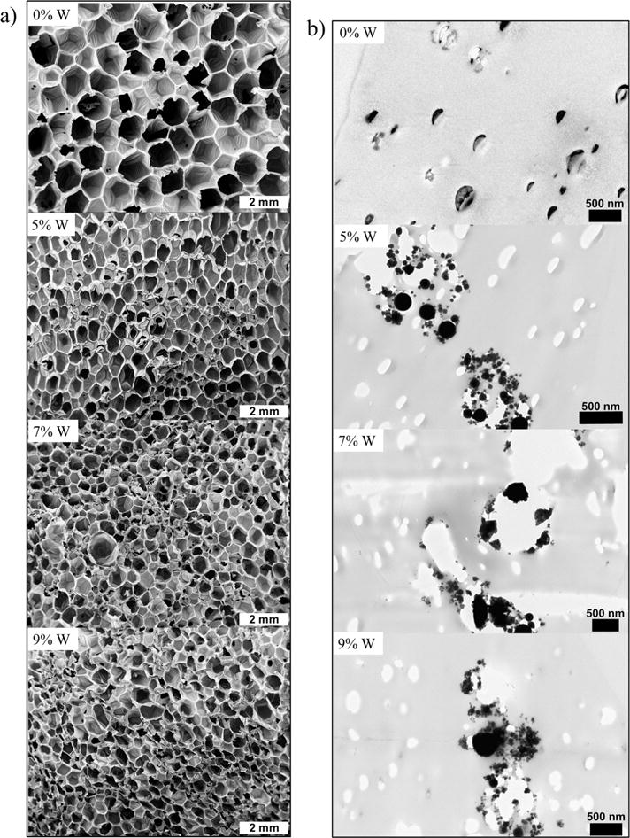
a) SEM images of the SMP nanocomposites at 10–11× magnification. b) TEM images of the SMP nanocomposites showing filler aggregates.
Figure 2.
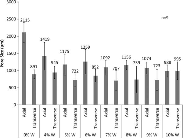
Pore sizes in the axial and transverse direction of SMP foams with increasing W content.
Transmission electron microscopy (TEM)
Incorporation of W nanoparticles into the SMP system resulted in aggregate formation at the nanoscale even at low concentrations (Fig. 1b). TEM image of the control (0%W) foam shows nanopores within the polymer struts which indicate the occurrence of these defects as a part of the foaming process rather than as a result of filler incorporation. However, 5%W, 7%W, and 9%W composites have filler aggregates in the polymer struts that imply poor dispersion of the nanoparticles with physical mixing.
X-ray imaging
Sufficient x-ray visibility was achieved for SMP nanocomposites with W loading greater than 6% (Fig. 3). Crimped foams attenuated x-rays through soft and hard tissue of the porcine head at various locations, suggesting acceptable visibility through qualitative analysis.
Figure 3.
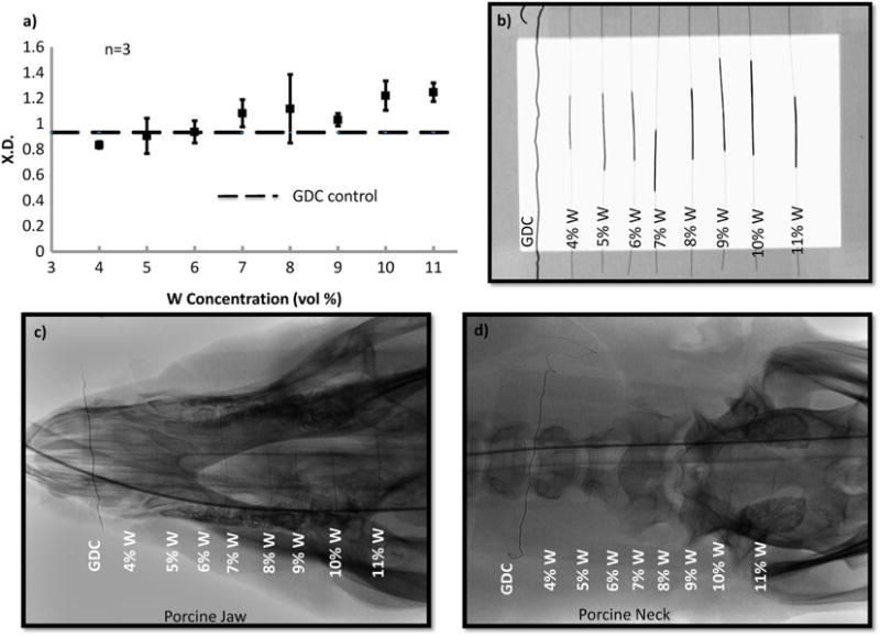
a) X-ray density of the SMP foams with increasing W content. b) Design of the frame mounted with crimped SMP foam over nitinol wire. c) X-ray image of the SMP foams through porcine jaw. d) X-ray image of the SMP foams through porcine neck. Panels a) and b) were acquired via collaboration with the Laboratory for Synthetic-Biologic Interactions using a Bruker In-Vivo Xtreme multimodal preclinical imaging system. Panels c) and d) were acquired via collaboration with Texas Institute of Preclinical Studies using a Philips Allura Xper FD 20 C-arm System.
X-ray density (XD)
Quantitative evaluation of foam visibility was conducted via XD analysis (Fig. 3). With increasing W loading, the crimped SMP attenuates x-ray more effectively, increasing from 0.8 to 1.2 at 45 KV. For SMP foams with greater than 6%W, average XD was larger than the GDC control (0.9). Filler addition successfully imparted radiopacity to the polymer system such that it will allow for use of smaller foam diameters without compromising x-ray visibility.
Differential scanning calorimetry (DSC)
Thermal characterization of the foams revealed increasing transition temperatures with greater W loading (Table 2). Dry Tg of the SMP foams increased by 10°C, while wet Tg increased by 7°C with higher filler content. Nanoparticle incorporation restricted polymer mobility at the molecular level and increased the number of physical crosslinks within the SMP network. The addition of these physical crosslinks requires greater heat input for the polymer to transition from the glassy to the rubbery state therefore shifting the Tg towards higher temperatures. This finding serves as a method for tuning thermal properties of the system for other applications that require a specific actuation temperature.
Tensile testing
Increasing W concentration in SMP foams changed mechanical properties compared to the control (Table 3, Fig. 4). An increase in Young’s modulus can be observed, from 2600 ± 200 kPa to 10,100 ± 400 kPa, for 4%W foams, indicating greater material stiffness. However, higher filler content resulted in decreasing stiffness because of disruption of the polymer matrix. Similarly, the tensile strength of the foams increased at 4%W, from 96 ± 2 kPa to 120 ± 20 kPa; however beyond this concentration the mechanical properties decrease as a result filler agglomerates replacing the polymer within the foam struts. Filler agglomerates within the foam struts resulted from poor dispersion because of relatively agglomerated starting materials, e.g. tungsten nanopowder. At high filler concentrations, W agglomerates caused particle bridging which resulted in weak planes in the nanocomposite. Toughness and strain at break of the SMP material also decreased compared to the control foam because of increased stiffness and aggregate formation because of high filler loading (Fig. 4). Overall, with higher W nanoparticle loading the foams became harder because of increased stiffness and decreasing polymer content within the struts. Additionally, variation in tensile strength and Young’s modulus of the higher loaded foams occurred because of changes in foam morphology as a result of heterogeneous pore sizes.
Table 3.
Key mechanical properties of the SMP foam nanocomposites
| W (vol %) | Modulus (kPa) | Ultimate tensile strength (kPa) | Toughness (J m−3) | Strain at break (%) |
|---|---|---|---|---|
| 0%W | 2598 ± 197 | 96 ± 23 | 97 ± 29 | 20 ± 1 |
| 4%W | 10,103 ± 439 | 117 ± 16 | 46 ± 7 | 9 ± 1 |
| 5%W | 6293 ± 415 | 107 ± 18 | 60 ± 12 | 12 ± 0 |
| 6%W | 5698 ± 1107 | 90 ± 5 | 48 ± 10 | 10 ± 4 |
| 7%W | 3098 ± 258 | 78 ± 3 | 40 ± 6 | 11 ± 1 |
| 8%W | 5472 ± 1909 | 82 ± 27 | 26 ± 9 | 7 ± 0 |
| 9%W | 2495 ± 1037 | 60 ± 6 | 27 ± 9 | 11 ± 2 |
| 10%W | 4075 ± 1567 | 67 ± 12 | 20 ± 13 | 9 ± 2 |
Figure 4.
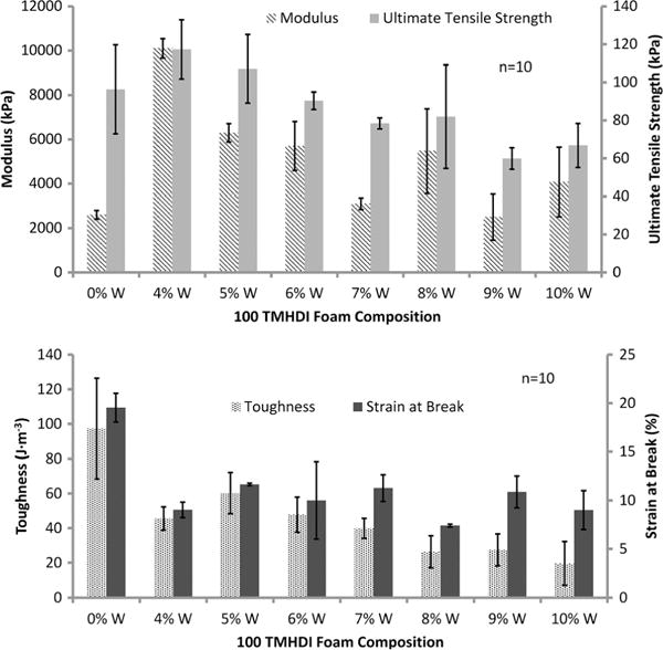
Mechanical properties of the SMP foams with increasing W content. This figure is available in colour online at wileyonlinelibrary.com/journal/pat
Actuation studies
Nanoparticle addition altered passive actuation kinetics of SMP foams at physiological temperature (Fig. 5). The control foam actuated within 4 min, as indicated by the inflection point of the plot. However, with increasing W loading the SMP experienced longer actuation times of 6, 8, and 10 min for 5%W, 7%W, and 9%W foams, respectively, which is reasonable given their increasing thermal transitions. Volume recovery (Table 2) of the foams remained greater than 80% for all foams, however, considerably less than the control foam because of increased molecular restrictions on the network mobility. Similarly, volume expansion of the foams decreased with W addition, from 63× ± 14 to 21× ± 4, for the control foams and 4%W loaded foams, respectively.
Figure 5.
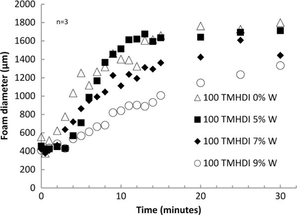
Actuation time of the SMP foams with increasing W content.
DISCUSSION
SMP foam nanocomposites were synthesized with inherent radiopacity by incorporating W nanoparticles within the polymer matrix during OH premix synthesis. W is a high Z number element which allowed it to effectively attenuate x-rays and impart visibility to SMP foams through soft and hard tissue. A smaller foam geometry was used for neurovascular applications; therefore higher filler loading was required to make the foams radiopaque. W concentrations greater than 6% resulted in sufficient foam visibility, when crimped, and had greater XD compared to the GDC control. Additionally, the SMP foams maintained their low density and high porosity, making them desirable for aneurysm occlusion devices because of their large volume expansion and high surface area. W nanoparticles served as a tool for controlling viscosity of the foam mixture and provided nucleation sites, which resulted in smaller and more isotropic pores with greater filler loading. This finding is critical for controlling the overall foam morphology and serves as a platform for material development for new medical applications that require specific pore sizes in polyurethane scaffolds. Filler dispersion improved significantly with nanoparticle content compared to the microcomposites developed by Rodriguez et al. W nanoparticles dispersion within the foam matrix was more homogeneous, compared to W microparticles, as seen by the lack of filler agglomerates within the struts and the foam membranes in the SEM images (Fig. 1a). However, filler aggregation still occurred on the nanoscale (Fig. 1b), indicating the need for further optimization of nanoparticle mixing into the foam matrix.
Thermal characterization of the foams showed increasing transition temperature, under dry and wet conditions, for foams with W loading greater than 5%. The nanoparticles restricted network mobility, thereby increasing polymer stiffness, and required higher temperature for the polymer to transition from the glassy to rubbery state. W addition provided greater control over the thermal properties of the SMP system. This functions as a potential tool for further tuning of the foams and prevention of premature water plasticization of foams in the catheter during device delivery. Similarly, passive actuation time of the foams increased with filler addition because of slower foam plasticization by water. Fortuitously, W nanoparticles have potential use providing greater control over the actuation kinetics of SMP foams, similar to altering the chemical backbone as studied by Hasan et al., to achieve longer working times for clinical applications. Volume recovery and expansion of the SMP foams decrease with greater W loading. However, the foams recover to 80% of their original diameter and expand up to 40× their original volume, maintaining their efficacy for aneurysm occlusion.
Last, mechanical properties of the SMP nanocomposites diminished with filler addition because of a large percentage of the polymer strut being replaced by W. While nanoparticles increased material stiffness and strength up to 4%W loading, an opposite effect was observed on toughness and strain-to-failure at all concentrations. W is traditionally used in low concentrations to develop mechanically robust composites; therefore lower toughness was expected for high filler concentration. Furthermore, the foams were tested below Tg. This could have a negative effect on mechanical properties as, above Tg, the rubbery polymer would align around the filler particles and provide higher toughness and strain-to-failure response. Additionally, increasing the crosslink density of the material because of filler loading would further lower material toughness and strain at break.
In conclusion, radiopaque SMP foam nanocomposites were developed with high W loading, up to 10% by volume, and high porosity for aneurysm occlusion applications. W nanoparticles successfully introduced radiopacity of the foams, using x-ray fluoroscopy, and made the device visible during transcatheter delivery and deployment within the aneurysm. Additionally, thermal properties of the composites were controlled by filler content with greater W concentrations resulting in higher Tg. Actuation profiles of the SMP composites were tailored with filler content because of increased stiffness which delayed actuation and mechanical properties were modified compared to unloaded foams. The new SMP nanocomposites provide a greater control over device visibility and actuation kinetics compared to the previously developed SMP systems by Rodriguez et al. and Hasan et al. Higher surface area of the nanoparticles afforded uniform filler dispersion and minimal foam destabilization compared to microparticles. Nanoparticles also served as a nucleating agent during foam synthesis and resulted in smaller cell sizes with increasing filler loading. Overall, the SMP foams have comparable radiopacity to current GDC coils and variable thermo-mechanical properties that make them optimal for use as embolic agents for neurovascular applications.
Acknowledgments
The authors would like thank Dr. Melissa Grunlan, Dr. Jennifer N. Rodriquez, Julie Grinde, Nicole Rivera, Todd Landsman, Landon Nash, Anthony Boyle, Harrison Emery, Brooke Cohen, Yichen Dai, and Ana Dominguez for their technical support on this research. We would like to acknowledge the Laboratory of Synthetic-Biologic Interactions, as well as its director Dr. Karen L. Wooley.
This work was supported by the National Institutes of Health/National Institute of Biomedical Imaging and Bioengineering Grant R01EB000462, the Welch Foundation (Welch Chair, #A-0001), the Laboratory for Synthetic–Biologic Interactions, Texas A&M Institute for Preclinical Studies, and the Texas A&M University Graduate Diversity Fellowship. Parts of this work were carried out in the Characterization Facility, University of Minnesota, a member of the NSF-funded Materials Research Facilities Network (www.mrfn.org) via the MRSEC program.
References
- 1.Ramakrishna S, Mayer J, Wintermantel E, Leong KW. Composites Science and Technology. 2001;61:1189–1224. [Google Scholar]
- 2.James NR, Philip J, Jayakrishnan A. Biomaterials. 2006;27:160–166. doi: 10.1016/j.biomaterials.2005.05.099. [DOI] [PubMed] [Google Scholar]
- 3.Ratner BD, Hoffman AS, Schoen FJ, Lemons JE. Biomaterials Science: An Introduction to Materials in Medicine. Academic Press; San Diego, CA: 1996. [Google Scholar]
- 4.Dawlee S. Studies on Radiopaque Polymers for Biomedical Applications Sree Chitra Tirunal Institute for Medical Sciences and Technology. Thiruvananthapuram India, Country: 2011. [Google Scholar]
- 5.Mottu F, Rüfenacht D, Doelker E. Investigational Radiology. 1999;34:323–335. doi: 10.1097/00004424-199905000-00001. [DOI] [PubMed] [Google Scholar]
- 6.Kiran S, James NR, Jayakrishnan A, Joseph R. J Biomed Mater Res A. 2012;100:3472–3479. doi: 10.1002/jbm.a.34295. [DOI] [PubMed] [Google Scholar]
- 7.Tbanoo BC, Sunny MC, Jayakrishnan A. Biomaterials. 1991;12:525–528. doi: 10.1016/0142-9612(91)90154-3. [DOI] [PubMed] [Google Scholar]
- 8.He J, Söderling E, Lassila LVJ, Vallittu PK. Dent Mater. 2012;28:110–117. doi: 10.1016/j.dental.2012.04.026. [DOI] [PubMed] [Google Scholar]
- 9.Tallia F, Gallo M, Pontiroli L, Baino F, Fiorilli S, Onida B, Anselmetti GC, Manca A, Vitale-Brovarone C. Mater Lett. 2014;130:281–284. [Google Scholar]
- 10.Reis LO, Kaizer MR, Ogliari FA, Collares FM, Moraes RR. International Journal of Adhesion & Adhesives. 2014;48:80–84. [Google Scholar]
- 11.Primack JE. J Prosthet Dent. 1972;28:363–368. doi: 10.1016/0022-3913(72)90236-3. [DOI] [PubMed] [Google Scholar]
- 12.Amirouche-Korichi A, Mouzali M, Watts DC. Dent Mater. 2009;25:1411–1418. doi: 10.1016/j.dental.2009.06.009. [DOI] [PubMed] [Google Scholar]
- 13.Amirouche A, Mouzali M, Watts DC. J Appl Polym Sci. 2007;104:1632–1639. [Google Scholar]
- 14.Rawls HR, Starr J, Kasten FH, Murray M, Smid J, Cabasso I. Dent Mater. 1990;6:250–255. doi: 10.1016/S0109-5641(05)80006-5. [DOI] [PubMed] [Google Scholar]
- 15.Kiran S, James NR, Joseph R, Jayakrishnan A. Biomaterials. 2009;30:5552–5559. doi: 10.1016/j.biomaterials.2009.06.049. [DOI] [PubMed] [Google Scholar]
- 16.Mawad D, Lauto A, Penciu A, Mehier H, Fenet B, Fessi H, Chevalier Y. Nanotechnology. 2010:21. doi: 10.1088/0957-4484/21/33/335603. [DOI] [PubMed] [Google Scholar]
- 17.Meng Q, Hu J. Composites Part A: Applied Science and Manufacturing. 2009;40:1661–1672. [Google Scholar]
- 18.Gall K, Dunn ML, Liu Y, Finch D, Munshi NA. Acta Mater. 2002;50:5115–5126. [Google Scholar]
- 19.Wilson TS, Bearinger JP, Herberg JL, Marion JE, Wright WJ, Evans CL, Maitland DJ. J Appl Polym Sci. 2007;106:540–551. [Google Scholar]
- 20.Hampikian JM, Heaton BC, Tong FC, Zhang Z, Wong CP. Mater Sci Eng C. 2006;26:1373–1379. [Google Scholar]
- 21.Singhal P, Boyle A, Brooks ML, Infanger S, Letts S, Small W, Maitland DJ, Wilson TS. Macromolecular Chemistry and Physics. 2013;214:1204–1214. doi: 10.1002/macp.201200342. [DOI] [PMC free article] [PubMed] [Google Scholar]
- 22.Small WT, Singhal P, Wilson TS, Maitland DJ. J Mater Chem. 2010;20:3356–3366. doi: 10.1039/B923717H. [DOI] [PMC free article] [PubMed] [Google Scholar]
- 23.Hearon K, Singhal P, Horn J, Small WT, Olsovsky C, Maitland KC, Wilson TS, Maitland DJ. Polymer reviews. 2013;53:41–75. doi: 10.1080/15583724.2012.751399. [DOI] [PMC free article] [PubMed] [Google Scholar]
- 24.Hasan SM, Raymond JE, Wilson TS, Keller BK, Maitland DJ. Macromolecular Chemistry and Physics. 2014;215:2420–2429. doi: 10.1002/macp.201400407. [DOI] [PMC free article] [PubMed] [Google Scholar]
- 25.Rodriguez JN, Yu YJ, Miller MW, Wilson TS, Hartman J, Clubb FJ, Gentry B, Maitland DJ. Ann Biomed Eng. 2012;40:883–897. doi: 10.1007/s10439-011-0468-1. [DOI] [PMC free article] [PubMed] [Google Scholar]
- 26.Hwang W, Singhal P, Miller MW, Maitland DJ. J Med Devices. 2013;7:0209321–0209322. [Google Scholar]
- 27.Kampmann C, Brzezinska R, Abidini M, Wenzel A, Wippermann CF, Habermehl P, Knuf M, Schumacher R. Pediatr Radiol. 2002;32:839–843. doi: 10.1007/s00247-002-0825-1. [DOI] [PubMed] [Google Scholar]
- 28.Peustera M, Fink C. Biomaterials. 2003;24:4057–4061. doi: 10.1016/s0142-9612(03)00274-6. [DOI] [PubMed] [Google Scholar]
- 29.Peuster M, Fink C, Wohlsein P, Bruegmann M, Gunther A, Kaese V, Niemeyer M, Haferkamp H. Biomaterials. 2003;24:393–399. doi: 10.1016/s0142-9612(02)00352-6. [DOI] [PubMed] [Google Scholar]
- 30.Jakhmola A, Antona N, Antona H, Messaddeq N, Hallouard F, Klymchenko A, Mely Y, Vandamme TF. Biomaterials. 2014;35:2981–2986. doi: 10.1016/j.biomaterials.2013.12.032. [DOI] [PubMed] [Google Scholar]