Abstract
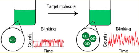
We demonstrate the first biosensing strategy that relies on quantum dot (QD) fluorescence blinking to report the presence of a target molecule. Unlike other biosensors that utilize QDs, our method does not require the analyte to induce any fluorescence intensity or color changes, making it readily applicable to a wide range of target species. Instead, our approach relies on the understanding that blinking, a single particle phenomenon, is obscured when several QDs lie within the detection volume of a confocal microscope. If QDs are engineered to aggregate when they encounter a particular target molecule, the observation of quasi-continuous emission should indicate its presence. As proof of concept, we programmed DNAs to drive rapid isothermal assembly of QDs in the presence of a target strand (oncogene K-ras). The assemblies, confirmed by various gel techniques, contained multiple QDs and were readily distinguished from free QDs by the absence of blinking.
Keywords: fluorescence blinking, quantum dots, lattices, biosensors, K-ras, nucleic acid engineering, strand displacement
Graphical abstract
In recent years, the field of biosensing has been introduced to colloidal luminescent semiconductor nanoparticles, better known as quantum dots (QDs).1–9 QDs are composed of a semiconducting core and a shell that protects against oxidation.10 Their size-tunable optical properties, due to quantum confinement, yield narrow, wavelength-specific emission spectra while maintaining a broad excitation range, resulting in polychromic fluorescence with a relatively uniform excitation energy. QDs offer a better shelf life and a higher resistance to photodegradation compared to small organic dyes, and their high surface area is amenable to a wide range of chemical modifications.7,11–13 These properties make them attractive for biosensing applications14 and have led to the development of inexpensive, sensitive, and multiplexed assays,15 e.g., the detection of oncogenic mRNAs using QD DNA conjugates.16,17
To date, all QD-based biosensing approaches have required a change in fluorescence intensity or color to confirm the presence or absence of a biomolecule.18,19 For this to occur, QDs must be engineered with a local coordination environment that, after selective interaction with an analyte, is able to undergo an electron or energy transfer reaction with the QD. The signal from this type of sensor is usually straightforward to detect, but it is not always convenient to design a QD system that can undergo such dramatic fluorescence changes, which are inherently sensitive to donor–acceptor distances and small changes in the local environment.
Here, we propose a more robust sensing strategy, which eliminates the need for any analyte-induced changes in the fluorescence from individual particles. Instead, QDs are programmed to aggregate after interaction with a target molecule and fluorescence differences between aggregated and single (not aggregated) QDs are used to report its detection. The proposed method relies on an intrinsic property of most QDs and many other chromophores known as fluorescence blinking. Single QDs typically exhibit binary fluorescence blinking trajectories (Figures 1 and S1) that alternate between bright (on) and dark (off) states,20 but when several QDs are observed, all the individual trajectories add up to yield a quasi-continuous fluorescence signal. By looking at the microscopic fluorescence and associated blinking trace it is, therefore, relatively easy to distinguish between single QDs and multiple QDs, even without the need for a reference sample.
Figure 1.
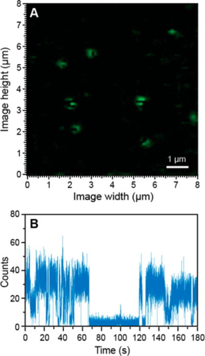
Representative QD fluorescence microscopy image (A) and blinking trace (B) of free QDs.
To prove this concept, we designed a QD-based biosensor that uses a DNA strand-displacement method21–26 to trigger the formation of QD lattices in the presence of a specific target strand as shown in Figure 2. Programmable DNA nano-assemblies27–30 have been shown to have an important impact in biosensing,31–35 and DNA is a well-suited biological material for the guided formation of QD assemblies because of its ability to self-assemble with its complementary strand.36–38 The working principle of our current biosensor is based on the thermodynamically driven reassociation of DNA strands assisted by ssDNA toeholds and triggered by a specific binding to target strand (a fragment of oncogene K-ras with codon 12 mutation39,40). The reassociation cascade leads to the formation of double biotinylated DNA duplexes, which rapidly cross-link the streptavidin-decorated QDs. Using confocal fluorescence microscopy we show that the target strand elicits a clear change in fluorescence trajectory from which we can infer the presence of the analyte and even estimate the number of particles in the resulting assemblies.
Figure 2.
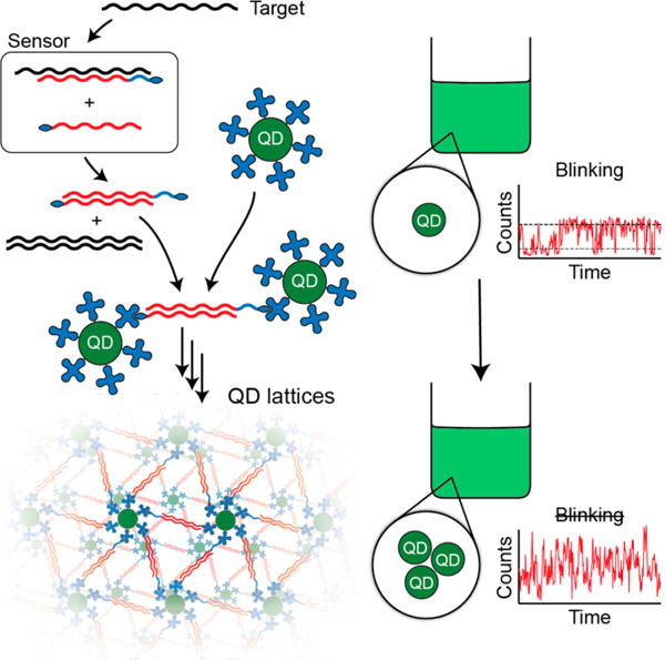
Schematics explaining the concept of biosensing with fluorescent blinking. Thermodynamically driven strand displacement in the presence of target sequence results in the formation of double biotinylated duplexes (in red) that upon addition of free quantum dots (QD) promotes formation of QD lattices. The additional blue section of the strand is required to stabilize biosensor formation.
EXPERIMENTAL SECTION
All specific experimental details are provided in Supporting Information.
Sequence Design and Sensor Preparation
Single-stranded DNAs entering the composition of biosensors were designed as schematically shown in Figure S2. Correct assemblies were tested with NUPACK.41 The full list of sequences used in this work is available in SI. All oligos were purchased from Integrated DNA Technologies (IDT), Inc. All duplexes were assembled as detailed elsewhere.26 All assemblies and reassociation experiments were analyzed by non-denaturing polyacrylamide gel electrophoresis (native-PAGE). Formation of QD-based lattices was analyzed with agarose gels.
Confocal Imaging
QD-biosensor solutions were analyzed by laser scanning confocal microscopy. Excitation was provided by a PicoQuant PDL 800-B pulsed laser with an LDH Series 470 nm laser head at a 10 MHz repetition frequency and power of 1.15 μW. Excitation pulses were coupled into a single-mode optical fiber, then directed to a 500 nm cutoff dichroic beam splitter before being focused onto the sample by a Zeiss 100× 1.25 NA oil immersion objective lens.
RESULTS AND DISCUSSION
The proof of concept biosensor is schematically explained in Figure 3A. A Target (4) interacts specifically with the Guard DNA (1), releasing a biotinylated DNA strand (2), which can then reassociate with a complementary strand (3) to form duplexes with two biotins (2 + 3). These can then cross-link streptavidin decorated QDs, yielding QD lattices. The lengths of the toeholds were defined based on the reassociation rules described elsewhere.42 The free energies of secondary structures were calculated41 to be −77 kcal/mol for (1 + 2) duplex, −65 kcal/mol for (2 + 3) duplex, and −97 kcal/mol for (1 + 4) duplex. The difference of −12 kcal/mol prevents (2 + 3) duplex formation in the biosensor setup ((1 + 2) + 3); however, the presence of target strand makes the formation of (2 + 3) more favorable, by −85 kcal/mol, due to (1 + 4) association. The melting temperatures shown in Figure 3B for all duplexes were measured43 to be 79.5 (77.8) °C for (1 + 2) duplex, 78.5 (76.3) °C for (2 + 3) duplex, and 78 (78) °C for (1 + 4) duplex and are in agreement with the predicted values (shown in parentheses).
Figure 3.
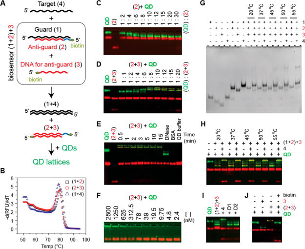
Recognition of target nucleic acids by programmable biosensor. A: Schematics explaining the working principle of biosensor and nomenclature. B: Melting temperatures measured for all duplexes participating in biosensing. C: Titration experiments carried out to determine the highest number of biotinylated DNAs to be bound to QDs. D: Titration experiments carried out to determine the ratio of double biotinylated (2 + 3) duplexes to QDs required for lattice formation. E: Time course of QD lattice formation and treatment of QD lattices with DNase. Red bands on all agarose gels stained with EtBr appear due to composition of the QD buffer that contains BSA. F: Series of dilutions of QD lattices performed in QD buffer. G: Total EtBr staining native-PAGE showing the strands displacement and biosensor activation (formation of 2 + 3) upon the presence of target strand (4). DNA for anti-guard strand (3) is the shortest and appears dim in (1 + 2) + 3 lanes; however, the formation of (2 + 3) duplexes is well observed in the following lanes. H: Target strand triggered formation of QD lattices analyzed with agarose gel. For (G,H), different incubation temperatures were tested. I: Target-specific formation of QD lattices is promoted by target (4) and not by “dummy” strands (D1 or D2). J: The formation of QD lattices is blocked in the presence of free biotin.
Multiple electrophoretic mobility shift assays (Figure 3) were done, prior to blinking analysis, to verify the working principle of this design. First, titration experiments showed that the maximum number of streptavidin–biotin interactions per QD was ∼15–20 (Figure 3C). Due to the increase of overall negative charge of QDs upon DNA binding, their migration rate increases dramatically. However, the formation of lattices makes it difficult for QDs to enter the agarose gel because of size limitations. We found (Figure 3D) that at least a 4:1 ratio of (2 + 3) duplexes to QDs was required for lattice formation. By mixing the preformed (2 + 3) duplexes with QDs (Figure 3E), the complete conversion of free QDs into the lattices was found to take just 30 s. We then demonstrated that QD lattices can be easily digested by DNase, releasing free QDs with shorter DNA fragments attached (Figure 3E). This experiment additionally confirmed that the lattice formation is driven by DNAs. Furthermore, the lowest concentration of lattices required for visualization with the gels was ∼5 nM (Figure 3F).
To test the reassociation of DNA strands in the biosensor and release of duplexes (2 + 3), a series of assemblies with and without target strands present were analyzed by native-PAGE (Figure 3G). Reassociation experiments were carried out at different incubation temperatures and the results confirm that the target sequence (4) causes the formation of duplexes (1 + 4) that result in the release of the biotinylated duplexes (2 + 3). Duplexes (2 + 3) were released most efficiently at an incubation temperature of 37 °C. In the same set of experiments, QDs were added to the biosensor ((1 + 2) + 3) with and without target strands (4) and analyzed on agarose gels, as shown in Figure 3H. Cleanest formation of QD lattices occurred at 20 and 37 °C. To test for specificity, two different “dummy” target strands of comparable lengths were tried (Figure 3I). Lattice formation was detected only in the presence of the correct target strands and was completely blocked in the presence of free biotin (Figure 3J). The experiments with different amounts of (4) mixed with constant amounts of (1 + 2) + 3 + QDs revealed the visible aggregation for ten times excess of sensor to target molecule (Figure S3).
Higher order bands were sometimes observed in reassociation experiments with the target strand, especially when elevated incubation temperatures (45, 50, and 55 °C) were used (Figure 3G). These bands were located higher than expected for double-stranded DNA and point to energetically stable complexes composed of more than two nucleic acids. These complexes decrease the efficiency of lattice formation (Figure 3H) by producing smear bands. To try to explain these bands we chose one possible complex composed of Guard, Anti-guard, and Target (1 + 2 + 4), and ran molecular dynamics (MD) simulations at four different temperatures: 27, 55, 60, and 95 °C. Simulation results, shown in Figure S4, indicate that Target, Guard, and Anti-guard strands can form a stable complex which can be maintained at high temperatures (55–60 °C) and can therefore explain the additional bands observed when the target strand is present.
Representative fluorescence micrographs (Figure 4A,B) show 75 μm square fields containing streptavidin decorated QDs mixed with sensor strands before (A) and after (B) the target strand was introduced. The samples were analyzed at ∼100 picomolar concentrations, which produced relatively dense particle distributions (Figure 4A,B), which points toward the feasibility of using much lower QD concentrations. Both images are scaled to the same intensity ranges and apart from a few brighter spots in Figure 4B there is little visual difference between them. Small regions in Figure 4A and B were reimaged and are shown in Figure 4C and D, respectively. Diffraction limits the resolution of the fluorescence spots to about 250 nm, so even moderately large QD lattices cannot be distinguished from single QDs by spot size alone; however, the particle in Figure 4C exhibits streaking in the fluorescence image, which is largely absent from the particle in Figure 4D. The streaking is due to blinking during a vertical raster scan across the particle and it indicates the presence of a single QD. The absence of streaking in Figure 4D strongly implies that multiple QDs are located within the focal spot. Note that in the absence of the target strand, the majority (>90%) of observed particles exhibited single QD blinking dynamics, while just a few were indicative of small groups of colocalized QDs (estimated 2–3 particles). In the Supporting Information Figures S5 and 6, we have also included fluorescence images, intensity histograms, and blinking traces of QD lattices formed at different temperature and QDs to biosensor ratios in the presence of target strands.
Figure 4.
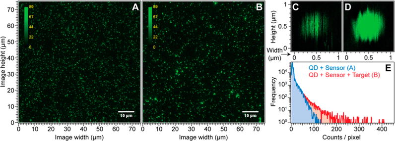
Representative QD fluorescence microscopy images. A: QDs incubated with the biosensor (1:10 ratio). B: QDs incubated with biosensor after addition of target strand. C: Single QD reimaged from the field in A, exhibits streaking due to blinking. D: QD aggregate from B, exhibits little streaking. E: Intensity histograms for the images in A and B.
Further evidence of lattice formation comes from analysis of the intensity distribution in Figure 4A and B, shown in Figure 4E. In the presence of the target strand the intensity histogram (red curve, corresponding to Figure 4B) has a significantly longer tail than the histogram recorded before the target strand was added (blue curve, corresponding to Figure 4A). The presence of high intensity spots in Figure 4B indicates the presence of QD lattices that have many QDs within the detection volume, all of which can contribute to the fluorescence intensity.
The key results that distinguish QD lattices (formed after introduction of target strands) from individual QDs are presented in Figures 5 and S5. Representative fluorescence blinking traces recorded on a bright spot from Figure 4A and B are shown in Figure 5A and B, respectively. Each trace has been scaled over the same intensity range. The blue trace in Figure 5A fluctuates randomly between bright (∼380 counts per 10 ms bin period) and dark (∼90 counts/bin) periods and is typical for a single QD. An intensity histogram calculated for this trace (Figure 5C) shows two peaks indicating the two intensity distributions.
Figure 5.
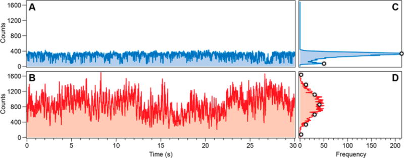
Representative blinking traces. A: Recorded on a bright spot in a fluorescence image from QDs incubated with biosensor (1:10 ratio). B: Recorded from a bright spot from QDs plus biosensor after incubation with target strands. Corresponding intensity histograms are shown in C and D. The white dots in D are derived from the two white intensity markers in C using a binomial model described in the text.
After introduction of the target strand the blinking trace in Figure 5B looks considerably different. Instead of binary blinking, the intensity fluctuates over a much wider range, indicating the lattice formation. Although particles in the lattices are still blinking, the total fluorescence for the whole lattice is rarely completely dark (off) or fully bright (on). This is reflected in the blinking histogram (Figure 5D), which shows a broad intensity distribution with a mean intensity greater than Figure 5C.
Assuming stochastic and independent blinking from each QD in a lattice we used a binomial model with single QD bright and dark intensities from Figure 5C (marked by open circles) to predict the expected blinking histograms for QD lattices. The intensity distribution for six QDs closely matches the measured distribution in Figure 5D (open circles), suggesting that there are at least six emitting QDs in this particular lattice. This type of analysis is approximate since it relies on the intensity of an unrelated single QD as a basis for the intensity distribution of the QD lattice; however, we illustrate in Figure S7 the intensity distributions expected from lattices containing different numbers of QDs.
The difference in blinking dynamics provides us with a reference-free way to distinguish the presence of QD lattices triggered by the addition of a target strand. A sample that yields bright spots with bimodal trajectories, like Figure 5A, clearly contains single QDs, while a sample that yields widely distributed intensity trajectories, like Figure 5B, must contain aggregated QD lattices and therefore indicates the presence of the target strand. The concentration of QD lattices required for the blinking study is in the picomolar range, which would be hard to detect using an ensemble of fluorescence techniques. Although the analytical performance of this method is a complex function of the absolute concentrations of sensor and target strands as well as QD concentration, false positives can be eliminated by surveying a representative number of fluorescent spots. Finally, we recognize that single particle fluorescence microscopy is complex compared to the ensemble of techniques used in other QD biosensing methods; however, previous studies have demonstrated the integration of confocal fluorescence with microfluidics for single particle analysis, which suggests that our proposal is realistic.44,45
CONCLUSION
In conclusion, we have demonstrated, for the first time, the application QD fluorescence blinking for biosensing. As a proof of concept, we constructed a DNA-based sensor that triggered QD lattice formation after introduction of a target molecule. These lattices could then be unequivocally identified by analysis of blinking trajectories using picomolar QD concentrations. Although this is currently a binary sensor, further investigation of the blinking response in different-sized lattices or with different interparticle distances could enable us to distinguish a wider range of situations. We anticipate that the current technique can also find multiple applications in the emerging field of RNA nanotechnology46–49 as a quick and parsimonious method for visualization of various programmable assemblies and their interactions.
Supplementary Material
Acknowledgments
We thank Dr. Troutman (UNC Charlotte) for helpful discussion. This publication was funded with the start-up funds provided by UNC Charlotte to K.A.A. H.S.K. and Y.G.Y. acknowledge support by NSF (CMMI-1150682). The computer support was provided by High Performance Computing (HPC) center at North Carolina State University. This project has been funded in whole or in part with Federal funds from the Frederick National Laboratory for Cancer Research, National Institutes of Health, under contract HHSN26120080001E. The content of this publication does not necessarily reflect the views or policies of the Department of Health and Human Services, nor does mention of trade names, commercial products or organizations imply endorsement by the U.S. Government. This Research was supported [in part] by the Intramural Research Program of the NIH, National Cancer Institute, Center for Cancer Research.
Footnotes
Supporting Information
The Supporting Information is available free of charge on the ACS Publications website at DOI: 10.1021/acssensors.6b00352.
All sequences used in this project, extended materials and methods section, and Figures S1–S7 presenting the blinking traces of individual quantum dots, biosensor designing principles, titration experiments, MD simulations, additional blinking experiments measured for biosensors tested at different conditions, and binomial probability distributions illustrating the likelihood of finding different number of QDs in the QD lattice (PDF)
Author Contributions
The manuscript was written through contributions of all authors. All authors have given approval to the final version of the manuscript.
Notes
The authors declare no competing financial interest.
References
- 1.Ho YP, Leong KW. Quantum dot-based theranostics. Nanoscale. 2010;2:60–68. doi: 10.1039/b9nr00178f. [DOI] [PMC free article] [PubMed] [Google Scholar]
- 2.Chou KF, Dennis AM. Forster Resonance Energy Transfer between Quantum Dot Donors and Quantum Dot Acceptors. Sensors. 2015;15:13288–13325. doi: 10.3390/s150613288. [DOI] [PMC free article] [PubMed] [Google Scholar]
- 3.Kovtun K, Arzeta-Ferrer X, Rosenthal SJ. Quantum Dot Approaches for Target-Based Drug Screening and Multiplexed Active Biosensing. Nanoscale. 2013;5:12072–12081. doi: 10.1039/c3nr02019c. [DOI] [PubMed] [Google Scholar]
- 4.Liu C, Kim K, Fan DL. Location deterministic biosensing from quantum-dot-nanowire assemblies. Appl Phys Lett. 2014;105:083123. doi: 10.1063/1.4893878. [DOI] [PMC free article] [PubMed] [Google Scholar]
- 5.Mattoussi H, Medintz IL, Clapp AR, Goldman ER, Jaiswal JK, Simon SM, Mauro JM. Luminescent Quantum Dot-Bioconjugates in Immunoassays, FRET, Biosensing, and Imaging Applications. JALA. 2004;9:28–32. [Google Scholar]
- 6.Zhou H, Zhang S, Liu J. Quantum-Dot Based Photoelectric Conversion for Biosensing. TrAC, Trends Anal Chem. 2015;67:56–73. [Google Scholar]
- 7.Wang Y, Hu R, Lin G, Roy I, Yong KT. Functionalized quantum dots for biosensing and bioimaging and concerns on toxicity. ACS Appl Mater Interfaces. 2013;5:2786–2799. doi: 10.1021/am302030a. [DOI] [PubMed] [Google Scholar]
- 8.Resch-Genger U, Grabolle M, Cavaliere-Jaricot S, Nitschke R, Nann T. Quantum dots versus organic dyes as fluorescent labels. Nat Methods. 2008;5:763–775. doi: 10.1038/nmeth.1248. [DOI] [PubMed] [Google Scholar]
- 9.Wegner KD, Hildebrandt N. Quantum dots: bright and versatile in vitro and in vivo fluorescence imaging biosensors. Chem Soc Rev. 2015;44:4792–4834. doi: 10.1039/c4cs00532e. [DOI] [PubMed] [Google Scholar]
- 10.Chakravarthy KV, Davidson BA, Helinski JD, Ding H, Law WC, Yong KT, Prasad PN, Knight PR. Doxorubicin-conjugated quantum dots to target alveolar macrophages and inflammation. Nanomedicine. 2011;7:88–96. doi: 10.1016/j.nano.2010.09.001. [DOI] [PMC free article] [PubMed] [Google Scholar]
- 11.Lee T, Yagati AK, Pi F, Sharma A, Choi JW, Guo P. Construction of RNA-Quantum Dot Chimera for Nanoscale Resistive Biomemory Application. ACS Nano. 2015;9:6675–6682. doi: 10.1021/acsnano.5b03269. [DOI] [PMC free article] [PubMed] [Google Scholar]
- 12.Zhou J, Yang Y, Zhang CY. Toward Biocompatible Semiconductor Quantum Dots: From Biosynthesis and Bioconjugation to Biomedical Application. Chem Rev. 2015;115:11669–11717. doi: 10.1021/acs.chemrev.5b00049. [DOI] [PubMed] [Google Scholar]
- 13.Oh JH, Park DH, Joo JH, Lee JS. Recent advances in chemical functionalization of nanoparticles with biomolecules for analytical applications. Anal Bioanal Chem. 2015;407:8627–8645. doi: 10.1007/s00216-015-8981-y. [DOI] [PubMed] [Google Scholar]
- 14.Freeman R, Girsh J, Willner I. Nucleic acid/quantum dots (QDs) hybrid systems for optical and photoelectrochemical sensing. ACS Appl Mater Interfaces. 2013;5:2815–2834. doi: 10.1021/am303189h. [DOI] [PubMed] [Google Scholar]
- 15.Li J, Zhu JJ. Quantum dots for fluorescent biosensing and bio-imaging applications. Analyst. 2013;138:2506–2515. doi: 10.1039/c3an36705c. [DOI] [PubMed] [Google Scholar]
- 16.Chan P, Yuen T, Ruf F, Gonzalez-Maeso J, Sealfon SC. Method for multiplex cellular detection of mRNAs using quantum dot fluorescent in situ hybridization. Nucleic Acids Res. 2005;33:e161. doi: 10.1093/nar/gni162. [DOI] [PMC free article] [PubMed] [Google Scholar]
- 17.Zhang W, Hubbard A, Brunhoeber P, Wang Y, Tang L. Automated multiplexing quantum dots in situ hybridization assay for simultaneous detection of ERG and PTEN gene status in prostate cancer. J Mol Diagn. 2013;15:754–764. doi: 10.1016/j.jmoldx.2013.06.005. [DOI] [PubMed] [Google Scholar]
- 18.Feng CL, Zhong XH, Steinhart M, Caminade AM, Majoral JP, Knoll W. Graded-Bandgap Quantum- Dot-Modified Nanotubes: A Sensitive Biosensor for Enhanced Detection of DNA Hybridization. Adv Mater. 2007;19:1933–1936. [Google Scholar]
- 19.Hansen JA, Wang J, Kawde AN, Xiang Y, Gothelf KV, Collins G. Quantum-dot/aptamer-based ultrasensitive multi-analyte electrochemical biosensor. J Am Chem Soc. 2006;128:2228–2229. doi: 10.1021/ja060005h. [DOI] [PubMed] [Google Scholar]
- 20.Efros AL, Rosen M. Random Telegraph Signal in the Photoluminescence Intensity of a Single Quantum Dot. Phys Rev Lett. 1997;78:1110–1113. [Google Scholar]
- 21.Seelig G, Soloveichik D, Zhang DY, Winfree E. Enzyme-free nucleic acid logic circuits. Science. 2006;314:1585–1588. doi: 10.1126/science.1132493. [DOI] [PubMed] [Google Scholar]
- 22.Turberfield AJ, Mitchell JC, Yurke B, Mills AP, Jr, Blakey MI, Simmel FC. DNA fuel for free-running nanomachines. Phys Rev Lett. 2003;90:118102. doi: 10.1103/PhysRevLett.90.118102. [DOI] [PubMed] [Google Scholar]
- 23.Machinek RR, Ouldridge TE, Haley NE, Bath J, Turberfield AJ. Programmable energy landscapes for kinetic control of DNA strand displacement. Nat Commun. 2014;5:5324. doi: 10.1038/ncomms6324. [DOI] [PubMed] [Google Scholar]
- 24.Srinivas N, Ouldridge TE, Sulc P, Schaeffer JM, Yurke B, Louis AA, Doye JP, Winfree E. On the biophysics and kinetics of toehold-mediated DNA strand displacement. Nucleic Acids Res. 2013;41:10641–10658. doi: 10.1093/nar/gkt801. [DOI] [PMC free article] [PubMed] [Google Scholar]
- 25.Sulc P, Ouldridge TE, Romano F, Doye JP, Louis AA. Modelling toehold-mediated RNA strand displacement. Biophys J. 2015;108:1238–1247. doi: 10.1016/j.bpj.2015.01.023. [DOI] [PMC free article] [PubMed] [Google Scholar]
- 26.Afonin KA, Viard M, Martins AN, Lockett SJ, Maciag AE, Freed EO, Heldman E, Jaeger L, Blumenthal R, Shapiro BA. Activation of different split functionalities on re-association of RNA-DNA hybrids. Nat Nanotechnol. 2013;8:296–304. doi: 10.1038/nnano.2013.44. [DOI] [PMC free article] [PubMed] [Google Scholar]
- 27.Pinheiro AV, Han D, Shih WM, Yan H. Challenges and opportunities for structural DNA nanotechnology. Nat Nanotechnol. 2011;6:763–772. doi: 10.1038/nnano.2011.187. [DOI] [PMC free article] [PubMed] [Google Scholar]
- 28.Genot AJ, Bath J, Turberfield AJ. Reversible logic circuits made of DNA. J Am Chem Soc. 2011;133:20080–20083. doi: 10.1021/ja208497p. [DOI] [PubMed] [Google Scholar]
- 29.Turberfield AJ. DNA nanotechnology: geometrical self-assembly. Nat Chem. 2011;3:580–581. doi: 10.1038/nchem.1097. [DOI] [PubMed] [Google Scholar]
- 30.Liedl T. Nanotechnology: Pathfinder for DNA constructs. Nature. 2015;523:412–413. doi: 10.1038/523412a. [DOI] [PubMed] [Google Scholar]
- 31.Liang H, Zhang XB, Lv Y, Gong L, Wang R, Zhu X, Yang R, Tan W. Functional DNA-containing nanomaterials: cellular applications in biosensing, imaging, and targeted therapy. Acc Chem Res. 2014;47:1891–1901. doi: 10.1021/ar500078f. [DOI] [PMC free article] [PubMed] [Google Scholar]
- 32.Zhao Y, Chen F, Li Q, Wang L, Fan C. Isothermal Amplification of Nucleic Acids. Chem Rev. 2015;115:12491–12545. doi: 10.1021/acs.chemrev.5b00428. [DOI] [PubMed] [Google Scholar]
- 33.Dirks RM, Pierce NA. Triggered amplification by hybridization chain reaction. Proc Natl Acad Sci U S A. 2004;101:15275–15278. doi: 10.1073/pnas.0407024101. [DOI] [PMC free article] [PubMed] [Google Scholar]
- 34.Huang D, Niu C, Ruan M, Wang X, Zeng G, Deng C. Highly sensitive strategy for Hg2+ detection in environmental water samples using long lifetime fluorescence quantum dots and gold nanoparticles. Environ Sci Technol. 2013;47:4392–4398. doi: 10.1021/es302967n. [DOI] [PubMed] [Google Scholar]
- 35.Huang D, Niu C, Wang X, Lv X, Zeng G. ″Turn-on″ fluorescent sensor for Hg2+ based on single-stranded DNA functionalized Mn:CdS/ZnS quantum dots and gold nanoparticles by time-gated mode. Anal Chem. 2013;85:1164–1170. doi: 10.1021/ac303084d. [DOI] [PubMed] [Google Scholar]
- 36.Mirkin CA, Letsinger RL, Mucic RC, Storhoff JJ. A DNA-based method for rationally assembling nanoparticles into macroscopic materials. Nature. 1996;382:607–609. doi: 10.1038/382607a0. [DOI] [PubMed] [Google Scholar]
- 37.Mitchell GP, Mirkin CA, Letsinger RL. Programmed Assembly of DNA Functionalized Quantum Dots. J Am Chem Soc. 1999;121:8122–8123. [Google Scholar]
- 38.Sharma J, Ke Y, Lin C, Chhabra R, Wang Q, Nangreave J, Liu Y, Yan H. DNA-tile-directed self-assembly of quantum dots into two-dimensional nanopatterns. Angew Chem, Int Ed. 2008;47:5157–5159. doi: 10.1002/anie.200801485. [DOI] [PMC free article] [PubMed] [Google Scholar]
- 39.Kam Y, Rubinstein A, Nissan A, Halle D, Yavin E. Detection of endogenous K-ras mRNA in living cells at a single base resolution by a PNA molecular beacon. Mol Pharmaceutics. 2012;9:685–693. doi: 10.1021/mp200505k. [DOI] [PubMed] [Google Scholar]
- 40.Minamoto T, Mai M, Ronai Z. K-ras mutation: early detection in molecular diagnosis and risk assessment of colorectal, pancreas, and lung cancers–a review. Cancer Detect Prev. 2000;24:1–12. [PubMed] [Google Scholar]
- 41.Zadeh JN, Steenberg CD, Bois JS, Wolfe BR, Pierce MB, Khan AR, Dirks RM, Pierce NA. NUPACK: Analysis and design of nucleic acid systems. J Comput Chem. 2011;32:170–173. doi: 10.1002/jcc.21596. [DOI] [PubMed] [Google Scholar]
- 42.Bindewald E, Afonin KA, Viard M, Zakrevsky P, Kim T, Shapiro BA. Multistrand Structure Prediction of Nucleic Acid Assemblies and Design of RNA Switches. Nano Lett. 2016;16:1726–1735. doi: 10.1021/acs.nanolett.5b04651. [DOI] [PMC free article] [PubMed] [Google Scholar]
- 43.Li H, Zhang K, Pi F, Guo S, Shlyakhtenko L, Chiu W, Shu D, Guo P. Controllable Self-Assembly of RNA Tetrahedrons with Precise Shape and Size for Cancer Targeting. Adv Mater. 2016;28:7501–7507. doi: 10.1002/adma.201601976. [DOI] [PMC free article] [PubMed] [Google Scholar]
- 44.Heus F, Giera M, de Kloe GE, van Iperen D, Buijs J, Nahar TT, Smit AB, Lingeman H, de Esch IJ, Niessen WM, Irth H, Kool J. Development of a microfluidic confocal fluorescence detection system for the hyphenation of nano-LC to on-line biochemical assays. Anal Bioanal Chem. 2010;398:3023–3032. doi: 10.1007/s00216-010-4210-x. [DOI] [PMC free article] [PubMed] [Google Scholar]
- 45.Puleo CM, Yeh HC, Liu KJ, Wang TH. Coupling confocal fluorescence detection and recirculating microfluidic control for single particle analysis in discrete nanoliter volumes. Lab Chip. 2008;8:822–825. doi: 10.1039/b717941c. [DOI] [PubMed] [Google Scholar]
- 46.Afonin KA, Kasprzak WK, Bindewald E, Kireeva M, Viard M, Kashlev M, Shapiro BA. In silico design and enzymatic synthesis of functional RNA nanoparticles. Acc Chem Res. 2014;47:1731–1741. doi: 10.1021/ar400329z. [DOI] [PMC free article] [PubMed] [Google Scholar]
- 47.Afonin KA, Desai R, Viard M, Kireeva ML, Bindewald E, Case CL, Maciag AE, Kasprzak WK, Kim T, Sappe A, Stepler M, Kewalramani VN, Kashlev M, Blumenthal R, Shapiro BA. Co-transcriptional production of RNA-DNA hybrids for simultaneous release of multiple split functionalities. Nucleic Acids Res. 2014;42:2085–2097. doi: 10.1093/nar/gkt1001. [DOI] [PMC free article] [PubMed] [Google Scholar]
- 48.Guo P. The emerging field of RNA nanotechnology. Nat Nanotechnol. 2010;5:833–842. doi: 10.1038/nnano.2010.231. [DOI] [PMC free article] [PubMed] [Google Scholar]
- 49.Khisamutdinov EF, Jasinski DL, Guo P. RNA as a boiling-resistant anionic polymer material to build robust structures with defined shape and stoichiometry. ACS Nano. 2014;8:4771–4781. doi: 10.1021/nn5006254. [DOI] [PMC free article] [PubMed] [Google Scholar]
Associated Data
This section collects any data citations, data availability statements, or supplementary materials included in this article.


