

Abstract
A bracing device for stabilizing cardiac catheters inside the heart was developed to provide surgical-level dexterity to minimally invasive catheter-based procedures for cardiac valve disease. The brace was designed to have a folding structure, which lies flat along a catheter during navigation through vasculature and then unfolds into a rigid bracing configuration after deployment across the interatrial septum. The brace was designed to be easily deployable, provide bracing support for a transseptal catheter, and also be compliant enough to be delivered to the heart via tortuous vasculature. This aims to improve dexterity in catheter-based mitral valve repair and enable other complex surgical procedures to be done with minimally invasive instruments.
1. Introduction
Heart disease is the leading cause of death in the U.S. and most other industrialized nations [1]. While some heart diseases can be treated with medicine, disorders of heart valves can disrupt the proper flow of blood by restricting flow (stenosis) or allowing leakage against the proper flow direction (regurgitation) [2]. This can negatively impact the ability of the heart to pump oxygenated blood to the rest of the body.
Interventional treatment of valve disorders involves repair or replacement. This can be done via open or endoscopic surgery, which requires stopping the heart and using a heart-lung bypass machine to oxygenate blood for the patient during surgery. Heart-lung bypass enables many life-saving procedures but it is also associated with cognitive deficits and increased mortality [3,4]. Catheterization, on the other hand, is a minimally invasive surgical beating heart technique in which a long, thin flexible tube is navigated through the patient vasculature to the heart [5]. The proximal end of the catheter is typically held by the clinician and the distal end contains sensors or working instruments. Catheters are advantageous for performing diagnostics and interventions while the heart is beating, thereby eliminating the need for heart-lung bypass.
Unfortunately, catheters are not well suited to performing dexterous tasks such as valve repair. While certain instances of valve replacement can be done via catheter [6], and simple cardiac defects are repaired with catheter-based occluders [7,8] or implants [9], complex valve repair requires a combination of stability and dexterity, which is not currently available with existing tools. Therefore, many valve repairs (and other similarly complex tasks) can currently only be performed while stopping the heart and using heart-lung bypass.
We propose a bracing solution to address the issues of providing stability, increase the potential force that can be applied to tissue, and therefore improve dexterity during catheter-based valve repair. The bracing solution must be flexible enough to be inserted through tortuous vasculature, be easily deployed inside the heart, and then provide bracing support to the distal section of the catheter. Existing medical flexible manipulator stabilization research has focused on externally delivering stitches to internal cardiac structures [10], redesigning the catheter itself [11,12], or inflatable structures for endoluminal procedures [13]. The research prototype presented in this work is an attachment to a standard catheter, which can be navigated through tortuous blood vessels and can be deployed to provide stability. Currently, there are no commercially available or research prototype cardiac catheter bracing solutions known to the authors, which meet the demanding insertability, deployability, and stability criteria addressed in this work.
This work provides the development and implementation of a device for bracing and stabilizing cardiac catheters. We discuss anatomical constraints and bracing strategies, the primary difficulties in creating an effective cardiac bracing structure, and the prototyping methods used to fabricate the brace. The prototype brace is then tested in bench top experiments. The results validate the feasibility of using the brace to stabilize against typical forces required for valve regurgitation repair. The success of the cardiac catheter brace may lead to greater stability and dexterity during catheter-based interventional procedures, therefore enabling a range of complex cardiac procedures (such as valve repair) to be done via catheterization while the heart is beating [14].
2. Design Specifications
While a bracing device could be useful in a broad range of intracardiac catheter procedures, the initial target procedure for device development is catheter-based mitral valve annuloplasty, which is currently performed through surgery in the left atrium (LA) with rigid tools. To perform this procedure through catheterization requires accessing the top of the mitral valve and installing devices around the annulus of the valve [15]. This procedure was chosen due to its demanding requirements for stability, dexterity, and force application to tissue. The difficulty of achieving this through catheterization poses many constraints on the design bracing device.
The LA is reached by introducing a catheter through the venous system (typically in the femoral vein), into the right atrium (RA), and then performing a transseptal puncture through the atrial septum (Fig. 1). From this position, the catheter can be flexed and navigated toward the top of the mitral valve. The catheter must be flexible as it bends through tortuous vasculature in order to reach the LA. Therefore, the bracing device must also be flexible as it is navigated toward the heart and then switched into a stiff bracing mode after reaching the destination.
Fig. 1.
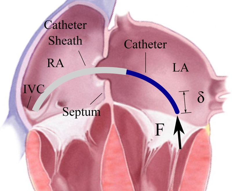
The transseptal catheter applies force to the mitral valve annulus. RA = right atrium, LA = left atrium, IVC = inferior vena cava.
The bracing device must also maintain a low profile during insertion, be easily deployable in the proper location (by applying under 10 N force), and be removable. The deployment force design specification is a guideline for how effortlessly the clinician should be able to deploy the brace. This is not the limit which can be applied to the device.
If the device is mounted to a catheter, then the device must include a clear inner lumen for working instruments to pass through to the surgical site. Any device attached to a catheter must be limited to a total maximum diameter of 24 Fr or 8 mm (the size of the MitraClip device, a proven clinical device that uses the same venous access as the proposed device [6]).
Installing our prototype annuloplasty devices around the valve annulus requires application of 1.5 N of force against tissue [16]. The catheter instrument applying the force must be rigidly braced to avoid displacement, or it must reduce displacement as much as possible. This brace will be designed to restrict displacement below 5 mm due to 2 N forces, corresponding to a moment which will be calculated and discussed.
The technical requirements are summarized:
Flexible enough to bend through tortuous vasculature.
Easily deployable (actuation force < 10 N) and removable.
Rigid enough to restrict deflection < 5 mm in response to 2 N force.
Maximum diameter < 24 Fr (8 mm).
Designed to have an open inner channel > 3 mm diameter which is compatible with existing catheter tools.
Safe, biocompatible, covered to prevent blood coagulation on its surface, and include no sharp components.
3. Design Methodology
3.1. Anatomy.
The cardiac catheter bracing device must mechanically couple the catheter to the cardiac anatomy in order to provide mechanical grounding support. Stability is improved by bracing the catheter against the structures that are as close to the catheter tip as possible. Through research on the structural support of various cardiac structures, initial prototypes, and discussions with clinicians and cardiac researchers, it was determined that a device fixed to the atrial septum is most likely to provide adequate bracing for a catheter. The atrial septum is close to the mitral valve; it undergoes minimal motion; there is a low likelihood of interfering with electrical signals, and it achieves additional stability from the set of fibrous rings connecting the atrial walls to the valves.
3.2. Strategy.
A bracing device with rigid segments connected by flexible joints is capable of providing the required stiffness for bracing support (Fig. 2). The strategy for installing the brace is as follows: Initially, the brace is undeployed, lying flat along the length of the catheter. The brace in its undeployed state is flexible enough to navigate through tortuous vasculature. The clinician uses standard practice for a transseptal puncture to cross the atrial septum. Next, the bracing catheter is advanced over the guidewire through the atrial septum (Fig. 3(a)). The distal tip is advanced into the LA and then deployed by a pull wire secured to the distal end of the brace catheter. The brace catheter is retracted until the deployed distal section contacts the atrial septum on the left side (Fig. 3(b)). The proximal brace half is then deployed by advancing the outer lumen (Fig. 3(c)). The catheter is guided through the inner lumen to the LA (Fig. 3(d)). The two deployed brace halves clamp the septum and provide support to the catheter. This process is repeatable such that the clinician can undo the brace deployment and reseat the device if necessary. This device was designed to be easily manually deployed with limited localization guidance (X-ray fluoroscopy should not be used unless necessary).
Fig. 2.
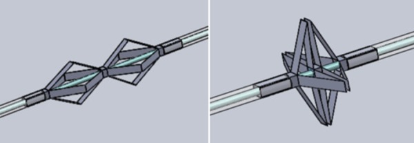
Computer assisted design model of rigid foldable brace
Fig. 3.

Brace deployment steps: (a) insert catheter sheath transeptally, (b) deploy distal brace and pull back to atrial septum, (c) deploy proximal brace and advance to atrial septum, and (d) insert catheter through inner lumen
The brace was designed to fold linkages into a triangular shape during bracing. The set of triangles in this arrangement enables the edges of the linkages to reach the edges of the septum where the cardiac tissue is most rigid. Force applied to the catheter tip causes a moment to occur about the brace. The tips of the brace linkages exert force against the septum. The geometry of the linkages is important because this affects which part of the septum it is braced against, how far the support extends into the LA, and the minimum turning radius during navigation. The required anatomical patient data, exact geometry of the linkage, and resulting sizing options are discussed in Sec. 6 on sizing analysis. A minimum of three linkages ensures proper bracing in all directions. Four linkages were used in this design.
While an effective structural design with rigid components can maintain stability in the braced configuration, the joint design must allow the catheter to bend in all directions during navigation through the vasculature. The most tortuous region along the path of the catheter occurs at the junction of the inferior vena cava (IVC) and the RA. An ultrasound (US) image of patient vasculature was measured to determine physiologically relevant values of IVC curvature for testing proof of concept insertion [17]. The arc of the IVC was estimated to curve 90 deg with radius of curvature 2 cm. The analytical design for geometry and flexibility of the device is discussed in Sec. 4.
4. Analysis
This investigation focuses on the two main components in the rigid foldable design: rigid links and flexible joints. Other features include a biasing ring (to prevent the links from lying completely flat) and deployment mechanism (enabling the clinician to sequentially deploy parts of the brace).
4.1. Linkage Geometry.
The proof-of-concept device developed here was designed for a patient with a small atrial diameter and septum (30 mm atrial diameter [18], 2 mm septum thickness [19]) to ensure that the smallest adult-sized device could be built. One side of the bracing linkage is the triangle shown in Fig. 4. The link lengths were A = 14 mm and B = 12 mm. This geometry would result in the distal tip of the brace being located 7.2 mm away from the septum in the 30 mm wide left atrium, which enables sufficient access for the clinician to work inside the atrium.
Fig. 4.

Brace linkage geometry
For joint design, it is important to know the range of angular rotation of each joint. The displacement x could be as large as A + B (which is 26 mm) and as small as A − B (which is 2 mm). The geometry of the triangle in Fig. 4 is given by the equations
| (1) |
| (2) |
| (3) |
| (4) |
4.2. Rigid Link and Catheter Design.
The linkage thickness was designed from critical force calculations to ensure that the links do not buckle as compressed columns. The critical force required to buckle a column is
| (5) |
The highest force a cardiologist may be expected to apply along the length of a catheter is approximately Fmax = 20 N. Modeling one link as a column fixed at both ends, the effective length was K = 0.5. For the case of two fixed ends, it is typically recommended to design with K = 0.65. The Young's modulus of stainless steel used in the prototype was E = 200 GPa. The smallest second moment of area of the link rectangular cross section is . The width, w, is determined by the diameter of the catheter. The thickness, t, is determined by the strength required to avoid buckling.
The catheter tubing was made of nylon inner tubing (ID: 2.2 mm, OD: 3.2 mm) and polytetrafluoroethylene outer tubing (ID: 3.2 mm, OD: 4.8 mm). The outer diameter was 5 mm (15 Fr), which is on the same order of magnitude as a cardiac catheter. The rigid links attached to the outside of the catheter increased the final diameter to 6 mm (18 Fr).
The brace prototype was designed to have four linkages spaced equally around the catheter circumference. More linkages use the available space of the round cross section of catheter tubing more efficiently. Also, more linkages provide more points of contact on the septum, which increases structural stability. Three linkages could provide the minimum acceptable bracing configuration. Four linkages of 3.2 mm width were used for the prototyping (Fig. 5).
Fig. 5.

Cross-sectional catheter brace geometry
Using w = 3.2 mm and L = 14 mm from Eq. (5), we can calculate the required link thickness to prevent buckling as h = 0.196 mm. With a 2X factor of safety to prevent buckling, the device must have stainless steel links of minimum 0.392 mm thickness. 0.410 mm thick stainless steel was used for prototyping. To improve patient safety, the metal links would be covered in a polymer sheet and the whole brace would be deployed for maximum 3 h.
4.3. Joint Design—Strategy.
The joints must bend through large angles with a small radius of curvature without failure. Additionally, the whole bracing structure must be flexible enough to bend through tortuous vasculature. This means that at least one of the joints must be flexible out of the plane of the bending triangle. Increasing out-of-plane flexibility reduces the bracing ability of the joint when the device is deployed. Therefore, the best brace will use few joints for bending out of plane. Joint 2 is the best candidate for out-of-plane flexibility because it allows the brace to be designed with three segments that are rigid to out-of-plane bending (Fig. 6, axial segments). Joints 1 and 3 can then be designed for zero out of plane bending and therefore can have higher bracing stiffness.
Fig. 6.

Diagram of the bracing device during insertion through vasculature. Joints 1 and 3 (denoted by circles) must rotate about a single living hinge axis. Joint 2 (denoted by squares) must bend in multiple axes without failing.
Plastic flexures are commonly used in thin extrusions for bends about sharp angles. Plastics have high tensile strengths and can be bent through much sharper bending radii than spring steel or other elastic metals (such as nitinol). Plastics could provide enough rigidity to constrain the linkages while also bending through the large angular deflections with a small radius of curvature. Bending strains were considered in designing the plastic hinge joints. The allowable strain of a material dictates how sharply it can bend and at what thicknesses. Referring to Fig. 7, ε = (L0 − L1)/L1, where L1 = θR and L0 = θ(R + t). Therefore, ϵ = θt/L1.
Fig. 7.

Bending dimensions of a living hinge [20]
Joint thicknesses and lengths must be designed to withstand the bending strains from large angular deflections. Some plastic deformation is acceptable, as the joints must withstand only a few deployments. Exact joint angle deflections will vary depending on the brace size chosen for each patient.
4.4. Joint Design—Materials.
Each of the three joints has different requirements for bending during insertion, bending during deployment, and bracing once deployed. Numerous joint materials and geometries were examined to determine which material would satisfy the requirements of each different joint.
4.4.1. Joint 1.
For the current brace size, the angular deflection of joint 1 reaches 59 deg. This means that there can be a mechanical stop beyond 59 deg to allow this joint to rotate freely but have little room for deflection in the bracing state (Fig. 8). Polyethylene terephthalate of 3 mil thickness was selected as a stiff yet extensible option. This thickness was chosen to maintain stiffness of the joint while minimizing the thickness added to the overall outer diameter. The required length to achieve the locking design was calculated as the arc length of the neutral axis of the bending joint, l = Rθ = 0.46 mm. This would cause a strain of ≈9%, which is significantly lower than the strain limit of polyethylene terephthalate.
Fig. 8.

Joint 1 shown deploying and then braced
4.4.2. Joint 2.
The design of joint 2 must accomplish two contradicting goals: joint 2 must be flexible enough to allow bending during insertion but also strong enough to brace the catheter when deployed. A material that is too soft would allow the joint to compress or translate during bracing, compromising the stiffness of the entire structure. To solve this problem, dual layers of thermoplastic polyurethane (TPU) (12 mil thick 85A polyurethane) were arranged with different amounts of slack on the top and bottom layers (Fig. 9). During joint 2 bending, the top layer of TPU is stretched. The excess TPU in the bottom layer kinks and becomes compressed by the two links. The kinked TPU resists deflections from forces along the length of the link during bracing. In bracing, it provides high stiffness, and when flat, it easily bends in multiple planes to enable insertion. TPU is also useful for its favorable blood contact properties, and a thinner layer can be used to cover the entire external surface of the device.
Fig. 9.

Joint 2 dual layer design
4.4.3. Joint 3.
The total bend angle of joint 3, typically in the range of 100 deg, is variable depending on patient anatomy. Joint 3 cannot be designed to lock at one particular angle in the same manner as joint 1 (Fig. 10). The joint length was decreased to the minimum size possible by manufacturing limitations: 0.13 mm. 2 mil nylon was selected for its smaller bend radius and strong adhesion to the stainless steel links. Strong adhesion is important especially at this joint because its design causes it to be the most prone to delaminating under shear stresses. Maximum strains ≈ 35% are below the maximum elongation of nylon (90%).
Fig. 10.

Joint 3 shown deploying and then braced
4.5. Assembly.
Metal frames of 0.41 mm thickness were cut using a 150 W laser. The laser cutting resolution was 0.13 mm. The frames were designed with thin bridges between individual metal links to precisely hold links apart before attaching the joints.
For the fabrication of the final proof-of-concept design, the plastic joints (joints 1 and 3) and metal links were laser cut in alignment frames. Pyralux B-stage 0.5 mil adhesive was used for a strong bond between the metal links and plastics joints. The materials were prepared for adhesion with ultrasonic cleaning and plasma etching. The adhesive was also cut in alignment frames. These five layers (Fig. 11) were pressed under 55 kg at 200 °C for 2 h to securely bond the joints to the metal frame using a process developed in Ref. [21].
Fig. 11.

Layers are aligned and then compressed under heat
The elastomeric joint 2 was subsequently secured by hand with medical device cyanoacrylate (Loctite 4011). Finally, the four linkages were removed from the frame by shearing the thin metallic bridges or by a release laser cut. The linkages were secured to the catheter tubing with cyanoacrylate. The final prototype is pictured in Fig. 12.
Fig. 12.

Final prototype
5. Results
5.1. Insertion.
A simulated IVC was built to demonstrate the ability of the brace to bend during insertion through vasculature (Fig. 13). The diameter of the curve is 2.2 cm (the normal adult range for IVC diameter is 1.5 cm to 2.5 cm). The radius of curvature is 4.47 cm and the curve angle is 90 deg. Section 6 presents a derivation of brace sizing based on patient geometry to ensure that the brace can turn through a range of patient sizes.
Fig. 13.

IVC analog for insertion testing
During a cardiac catheterization procedure, a guide wire would first be delivered to the target destination, and then the bracing catheter would be guided along the wire. In this insertion feasibility test, the undeployed brace catheter was manually navigated through the simulated IVC without a guide wire (Fig. 14). This demonstrated that the brace was sufficiently flexible in its undeployed configuration.
Fig. 14.

Braced catheter turning through the IVC analog
5.2. Deployment.
A force-testing instrument (Instron) was used for measuring the forces needed to deploy the brace (Fig. 15). One side of the brace was deployed as shown in Fig. 15. This was achieved by translating the outer tube downward over the inner tube. Inner and outer tubes were secured at the central location between the two halves of the brace. Thus, holding both inner and outer tubes fixed for the second brace side allowed for controlled deployment of one side of the brace. The bias ring, which prevents the linkages from lying completely flat against the catheter, prevents the brace from becoming undeployable.
Fig. 15.

Deployment testing setup
Figure 16 shows deployment force test results collected with the test fixture in Fig. 15. After the Instron comes into full contact with the device for deployment, 1.2 N additional force begins deployment. Then the force reduces to between 0.6 N and 0.8 N.
Fig. 16.
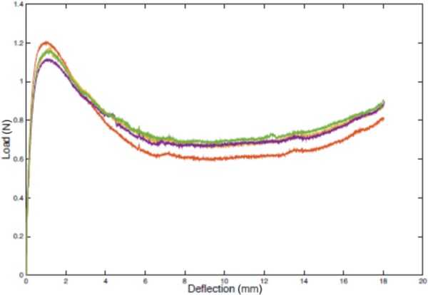
Experimental deployment force
The system was lubricated but not entirely frictionless. The friction between tubes was measured separately (Fig. 17) and may account for about 10% of the recorded deployment force. This low input force result indicates that manual deployment is feasible and unlikely to damage the brace in the bench top environment. During a clinical procedure, the amount of friction force the clinician must overcome to deploy the brace will vary due to the lengths and mechanical properties of the catheters, vessel tortuosity, and blood. Still, the force required to deploy the brace is expected to be well below the 10 N deployment force specification.
Fig. 17.
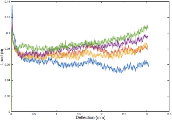
Friction between catheter tubes
5.3. Bracing.
5.3.1. Test Setup.
The force-testing instrument was used to measure the stiffness of the deployed brace. The bracing test setup is shown in Fig. 18. A rigid 0.64 cm acrylic sheet provided vertical stability and was clamped into the Instron with the help of two flanges to ensure strong clamping and orthogonality. Interchangeable septum analogs were attached to the blue 0.64 cm acrylic base. The brace/catheter system was threaded through an oversized (7 mm diameter) hole in the septum. The septum hole was oversized to avoid supporting the catheter. This is consistent with cardiac anatomy because the atrial septum does not provide structural support to transseptal catheters.
Fig. 18.

Bracing testing setup
The braced catheter was manually deployed and clamped in the braced position with collar clamps. The brace was fully deployed on both sides of the acrylic septum. The test method was set to compressive extension with an end of test stoppage point at maximum load 2 N. For each test, a plunger was positioned above the catheter brace centered 3 mm away from the end of the brace. The force at the plunger can be summarized by a resultant force acting 3 mm beyond joint 1 (which is 7.2 mm away from the septum). Thus, the moment arm was 10.2 mm.
Prior to each trial, the plunger arm was positioned above the catheter sheath so that the load cell of the force tester was initially unloaded. The plunger displaced downward a small distance before making contact with the catheter and applying force. To calculate brace stiffness, the actual vertical displacement of the catheter in response to 2 N must be extracted. This is equivalent to the deflection of the plunger arm after making contact with the catheter until the 2 N end of test is reached. Figure 19 shows five example bracing tests.
Fig. 19.

Example bracing data
The overall catheter deflection was the difference between the maximum and minimum extension values. The leftmost (first) trial was a system calibration that effectively seated the catheter before applying further forces. Subsequent trials represent accurate bracing results. The displacement resolution of the force tester was <0.003 mm. The force measurement accuracy was within 0.5% of indicated load.
5.3.2. Test Results.
After seating the catheter as in the first trial of Fig. 19, a 2 N force was applied to the catheter 4 times. This process adjusting the catheter, reseating, and collecting 4 data points was done 10 times for a total of 40 data point shown in Fig. 20. The central catheter and the septum analog were rigid. Half of the tests were done such that two of the brace arms were deployed vertically in the same plane as the plunger's applied force (Fig. 21 (left)). In the remaining deployments, the brace was rotated about its axis by 45 deg to assess the effect of forces applied between arms of the brace (Fig. 21 (right)). This distinction is made because it is important to know whether the angle between the catheter applied force and the brace rotation affects the bracing stiffness. Due to the imaging methods currently available in interventional cardiology catheter labs and the amount of torsional windup, which occurs along the length of a catheter, it would be challenging to control the rotational orientation of the brace. No statistically significant difference was found between these two cases (p = 0.3804). Both cases are shown together in Fig. 20.
Fig. 20.

Bracing results histogram from 40 loadings
Fig. 21.

Rotational orientation of the brace
This result shows a very high stiffness at the tip of the brace (nearly 6 N/mm). Figure 22 shows how the stiffness at the end of the brace corresponds to the stiffness of the brace/catheter system at the catheter tip. We assume that the catheter itself is a rigid body, which could be possible with the continued development of catheters that can stiffen in place. We use this assumption to calculate the stiffness of the brace/catheter system at the catheter tip from Fig. 22 as kt = Fxx2/δxt2. This calculation evaluates the stiffness of the brace only, as though the force to the catheter tip was being applied to the brace.
Fig. 22.

Catheter tip stiffness derivation
An estimated stiffness of a catheter tip at any location in the atrium can be extrapolated from the measured stiffness of the brace at x = 10.2 mm (Fig. 23). With an overall desired target stiffness of k = 2 N/5 mm = 0.4 N/mm, this brace will meet the target for any length of catheter protruding beyond the brace and into the LA. This suggests that even with a very stiff brace, the bracing location must be at the septum or closer. The stiffness of the septum becomes the limiting factor for catheter bracing.
Fig. 23.

Calculated range of catheter tip stiffness
Since stiffness of the working catheter is a contributing factor to the overall stiffness of the system, bracing data were also collected to determine this effect. A set of tests was conducted while the inner lumen had no inner catheter for support. The deflection at the brace tip increased from 0.335 mm to 0.381 mm (p = 0.0179). This increase in deflection is the result of a hollow catheter (with no inner support) bending in response to an applied moment. Because it is expected that this brace will always be used with a working catheter inside, this hollow stiffness measurement demonstrates the lower bound of bracing stiffness.
The stiffness of the septum used during bench top testing also contributes to the overall stiffness of the system. The brace must also succeed in supporting the catheter when the septum is compliant (rather than rigid acrylic used in our initial tests). Clinical data of the mechanical properties of the human interatrial septum have not been found in the literature. We therefore conducted an additional set of bracing tests while bracing onto a rubber septum analog. The rubber chosen for this experiment was 1.59 mm thickness shore 60 A durometer neoprene rubber constrained in a 4 cm rigid circle.
First, the rubber septum itself was tested to determine its stiffness. The rubber septum analog was fastened into the test rig in several different configurations to make the septum more or less stiff. The rubber was orthogonal to the plunger and the force tester was used to measure the rubber stiffness, ks, assuming a point load force was applied. The force applied orthogonally to the rubber is considered analogous to reaction forces between the loaded brace and the septum.
After assessing the stiffness of the septum, the test setup of Fig. 18 was repeated except with the rubber septum in place of the acrylic plastic. The updated test setup is pictured in Fig. 24. A 2 N force was applied to the brace tip when loaded on the rubber septum. The overall catheter and brace system deflection is plotted with respect to the deflection of the septum. This motivates the idea that the physical environment is the limiting factor to the success of the brace.
Fig. 24.

Bracing test setup with rubber septum analog
The deflection of the braced catheter system is linearly correlated (R2 = 0.9095) with the compliance of the rubber (Fig. 25). Therefore, the compliance of the in vivo septum can be assumed to be the limiting factor in terms of overall brace stiffness. Because human septum properties are unknown and not adjustable, the best way to ensure stiffest possible bracing is to reach the areas of the septum that will provide the strongest brace grounding. This can be achieved by informed sizing of the brace, to be discussed in Sec. 6.
Fig. 25.

Brace deflections for various septum analogs
6. Clinical Sizing Analysis
This section presents an algorithm for determining the correctly sized brace for a given patient. With a range of patient anatomical information, it is possible to determine a set of discretely sized brace options. First, the IVC curve must be considered. The majority of the vascular pathway from the femoral vein to the RA is straight in patients with normal vasculature. The turn from the IVC into the RA is typically the most tortuous section and thus the limiting factor (Fig. 26).
Fig. 26.

Defining IVC geometry
Pre-operative U.S. imaging can be used to determine the curvature of the pathway from the IVC into the atria toward the fossa ovalis of the atrial septum. Standard image processing can fit an arc to this curved pathway. Perhaps, the two easiest dimensions to define the curve from this type of arc fit are the radius of curvature of the arc, R, and the linear distance between the ends of the arc, d. The diameter of the IVC, DIVC, can also be determined through standard ultrasound imaging protocol. Recording this dimension is already standard protocol. With these three pre-operative measurements (R, d, and DIVC), the geometry of the curved pathway is completely defined.
The following equations define the other variables in Fig. 26 in terms of R, d, and DIVC. From the triangle defined by d, R, and θ, . The supplementary angle to θ defines another triangle that shares chord length d, where and . The height of this triangle is now defined as . Finally, this height can be decomposed into the portion that is inside the curve, , and the portion external to the curve ϵ = h1 − δ. The equation for δ comes from simple geometry of a chord (Fig. 27). R = x + δ and .
Fig. 27.

Chord geometry
Now that the geometry of the catheter pathway is defined, the catheter can be placed inside the pathway to determine the constraints on sizing imposed by the curvature and diameter of the IVC. Figure 28 shows the catheter curving through a representative IVC with sufficient space to make the turn. The radial positioning of the catheter as it makes this curve is very challenging to control. Thus, the worst case scenario will be considered throughout this analysis. That scenario is when the plane of curvature (cross section shown in Fig. 28) is exactly coincident with the midline of a link as it bends through the inner section of the curve (requiring the largest opening of the brace during curving). All other radial configurations will require less opening of the brace and thus less overall volumetric space. It is important to note that this is a completely general solution for any number of linkages. The schematic in Fig. 28 places the brace at the outer curve to determine the maximum possible brace sizing for given IVC dimensions.
Fig. 28.

Catheter brace turning through IVC and corresponding geometric model
The angle α is the critical dimension to establish the amount of radial expansion of the brace imposed by the curvature of the IVC. To design for the more difficult case of a small radius of curvature, the following analysis will focus on solutions where the longest rigid length is less than d. Figure 29 defines the sizes of the two main components of the brace to be referred to in future steps of the analysis. A and B are the respective lengths of the triangle that is the crux of the bracing. Joint 2 between lengths A and B is the elastomeric joint that has non-negligible length and can bend and twist in planes other than the bending plane required for deployment. The other joints are designed to only rotate in the plane of the cross section shown below. In this insertion analysis, therefore, joint 2 defines a break between rigid links and joints 1 and 3 do not. Lengths A and B, as defined for the purposes of the analysis, include the lengths of the individual stainless steel pieces and roughly half the length of the elastomeric joint as it contributes to the lengths of the triangle. Finally, length D is defined as the central rigid length composed of both B links and the piece through the septum, s, as in D = 2B + s. s represents the distance between B links where the atrial septum is.
Fig. 29.

Brace geometry
The maximum expansion of the brace occurs for the largest possible value of (the supplementary angle to α) or conversely the smallest value of α. Considering the catheter proceeding through the curve, touching the outer curve, the angle between any two links increases as the first link enters the arc region. The angle between the links increases and continues to increase as the second link enters the arc. reaches a maximum when both links are inside the confines of the arc. will remain constant as the connected links proceed around the curve and will begin to decrease when the first length begins to exit the arc to a straight trajectory. Thus, maximum can be determined for a given joint (and this is a symmetric problem so the analysis only needs to be done once) when the two connecting links are anywhere inside the curved portion of the path. One such position is shown in Fig. 30. α can be defined using Fig. 30 to derive the following equations: , and . Now, triangle ADC is defined and angle α can be determined using the law of cosines, .
Fig. 30.

Defining the bend angle between joints during insertion
Consider the central part of the curve to determine what brace sizing can fit a given curve. The three consecutive schematics of Fig. 31 show A and B getting larger. α increases as a result and the brace gets closer to filling the entire IVC. Next, the model will embrace two conservative estimates to build in a factor of safety. First, the septum length is considered to be negligibly small such that triangle BhbX exists. This assumes the B arm is always slightly closer in to the center than is physically possible (there must be some septum length s).
Fig. 31.

Defining the largest possible brace. (a) Small size brace can easily curve through the IVC, (b) medium size brace can curve through the IVC with a small margin of error, and (c) large size brace cannot curve through the IVC.
The second conservative consideration comes in determining the final cutoff for angle a2. Angle a2 defines where the tip of link B is in relation to the apex of the curve. To ensure that link B never interferes with the wall of the IVC and the brace can make it around the entire curve, a conservative mandate that a2 ≤ 90 deg is enforced. This imposes a small area of safety (shaded area in Fig. 31(b)). Thus, the braces in Figs. 31(a) and 31(b) would pass, whereas the brace in Fig. 31(c) would fail. The final calculations to determine a2 are below.
First, we define hb in Fig. 32. Using the same chord geometry as in Fig. 27, . Thus, hb = DIVC − ha − w. The law of cosines is applied to calculate a2 as in , and .
Fig. 32.

Defining IVC geometry with respect to the long rigid brace segment
Finally, this algorithm can be employed to inform clinicians' decisions about sizing based solely on three pre-operative measurements. For IVC curvature, the final constraint is α2 ≤ 90 deg. Since θ will likely be about 90 deg, it is most interesting to consider variation in DIVC and R (the radius of curvature of the IVC). The diameter of an adult IVC ranges from 15 mm to 25 mm. Here, a 10–20 mm range is presented to address the smaller, more restrictive end of the spectrum and include children in the analysis [22].
For discrete possible values of A, the maximum possible value of B is plotted as a function of IVC diameter. Thus, all B lengths below each A curve represent possible combinations of B and A where vertical segments of these possibilities represent all possibilities for a given DIVC. There are two additional sizing constraints beyond the curvature of the IVC. First, the triangular brace design only functions as a triangular brace that reaches the septum for A > B. Second, the distal half of the brace must be able to fit inside the left atrium in a flat configuration before deployment. The diameter of the left atrium is thus an important limiting factor where A + B < Datria. The normal range for the diameter of the left atrium is 28–40 mm [23].
Figure 33 shows potential A and B values the clinician could select as a function of DIVC for a patient with parameters Datria = 30 mm, R = 44.75 mm, and DIVC = 10–20 mm. The constraint A > B caps Bmax values at Bmax = A. The atrium size limits the highest B value, which determines how high on the atrial septum the brace can reach. The maximum value for B is 15 mm (half of 30 mm). For brace hypotenuse A > 15 mm, length B is limited to Datria − A.
Fig. 33.

Brace dimension options as a function of DIVC. Datria = 30 mm, R = 44.75 mm, and DIVC = 10–20 mm
The clinician seeks to maximize dimensions H (the height of the brace about the septum) and L (the distance of the brace into the atrium when deployed) in Fig. 34. For any given A and B, H and L are defined quantities with small variability due to septum thickness variability where the brace is seated. For any brace, the brace dimension s will be chosen such that it is thicker than the septum at likely points of brace tip contact. A septum thickness profile can be estimated with pre-operative imaging to motivate this size selection. Take the smallest case, for example. 2 mm is chosen here as a reasonable small size to accommodate septa thinner than 2 mm. The clinician ultimately wants to choose a brace size (determined by s, A, and B) for a desired H and L. To accommodate this range, the minimal H value (for infinitely thin septum) and its corresponding L will be considered.
Fig. 34.

Defining lengths L and H
L defines the possible working space inside the atrium, . L also determines what fractional length of the catheter is supported by the brace. Therefore, longer L increases ktip (the stiffness at the tip of the catheter) because more of the catheter body is supported by the rigid brace. However, L must be chosen to leave sufficient room for access to the necessary areas of the atrium.
H is given by . For bracing purposes, it is also desirable to maximize H to reach the upper and lower edges of the patient's septum. Recall that the septum meets the atrial wall near the base of the valves where the fibrous skeleton of the heart may provide a rigid bracing seat. The height of the atrium can also be determined by pre-operative US.
Finally, we present Fig. 35 to the clinician, which summarizes anatomical constraints and enables the clinician to select their desired L and H values. Figure 35 represents a patient with Datria = 30 mm and DIVC = 15 mm. Assume septum thickness s is small compared to link lengths A and B, and H ≈ B. The shaded green area represents possible selections for H and L on an individual patient basis. The curve represents anatomical constraints limiting maximum sizes of A and B, which in turn limit H and L. For a patient of Datria = 30 mm, the curve is limited by Datria. For larger Datria, the limiting factor becomes IVC parameters.
Fig. 35.

Clinical decision matrix for choosing H and L values given patient parameters Datria = 30 mm and DIVC = 15 mm
A population study to determine the full range of potential anatomies would allow optimization of discrete sizing choices. These could be represented as dots within these shaded areas. The clinician would then have the knowledge of which existing sized braces could fit their patient. With multiple size options, they could then choose the best size for their needs (which may require negotiation between optimal H and L).
7. Discussion
The cardiac catheter bracing prototype was designed for flexibility to steer through tortuous blood vessels and rigidity to provide bracing support when deployed. Bench top test results demonstrated that the brace successfully could be inserted through tortuous vasculature and deployed with very low forces. Bracing tests were conducted by applying force to the catheter inside the brace and measuring the resulting displacement. These tests were repeated in a rigid and a nonrigid septum. In both cases, the brace provided additional stiffness to the catheter.
All of the technical requirements outlined in Sec. 2 were met. In particular, the actuation force spec was <10 N, and test results demonstrated 1.2 N. The minimum required tip stiffness spec ≥0.4 N/mm was exceeded by the actual measured stiffness range 0.7–6.0 N/mm. The maximum diameter spec was <24 Fr (8 mm), and the final prototype was 18 Fr (6 mm).
Finally, an analytical patient-specific sizing algorithm was derived. A calculator could be created such that the best brace size is automatically selected from key anatomical information. This could involve automatic segmentation from medical images and/or a clinician entering manually determined values.
Additional work aims toward testing the brace in ex vivo and then in vivo porcine models. A protective outer coating is necessary to encapsulate the entire device. There is a wide range of biocompatible polymers that could serve as a soft outer covering. Stretchable elastomers, like TPU, could expand over the device as it deploys. Alternatively, less elastic plastics like polytetrafluoroethylene could be loose and folded up prior to deployment and then wrapped tightly over the device when deployed.
The sizing algorithm must be experimentally verified and population tested to determine the best sizes for manufacturing. The development of a bracing mechanism or strategy is critical to the overall success of improving surgical dexterity through cardiac catheters, with the aim of enabling more cardiac procedures to be feasible through catheterization.
8. Conclusion
This work develops a novel device to improve catheter-based procedures by mechanically supporting flexible catheter tools inside the beating heart. The cardiac catheter brace maintains a low profile as part of a flexible catheter during navigation. Upon deployment, it provides high stiffness to brace catheters against safe and structurally supportive cardiac anatomy. This will allow for enhanced surgical dexterity through catheters, allowing precise manipulation of left atrial tissue during procedures like mitral valve repair. The innovation could greatly benefit patients by enabling complex procedures to be done with less invasive surgical instruments.
Acknowledgment
The authors would like to thank Alperen Degirmenci, Yashraj Narang, Robert J. Wood, Michelle Rosen, Stephanie Kladikis, Diego Porras, Stan Cotreau, Elaine Kristant, Michael Smith, and Samuel B. Kesner.
Contributor Information
Leah P. Gaffney, Paulson School of Engineering and Applied Sciences, , Harvard University, , Cambridge, MA 02138 , e-mail: leahgaffney@post.harvard.edu
Paul M. Loschak, Paulson School of Engineering and Applied Sciences, , Harvard University, , Cambridge, MA 02138 , e-mail: loschak@seas.harvard.edu.
Robert D. Howe, Paulson School of Engineering and Applied Sciences, , Harvard University, , Cambridge, MA 02138 , e-mail: howe@seas.harvard.edu
Funding Data
Harvard Paulson School of Engineering and American Heart Association (#15PRE22710043).
National Institutes of Health (#1R21EB018938).
References
- [1]. Kung, H.-C. , Hoyert, D. L. , Xu, J. , and Murphy, S. L. , 2008, “ Deaths: Final Data for 2005,” Natl. Vital Stat. Rep., 56(10), pp. 1–120.http://www.nber.org/mortality/2005/docs/Deaths_FinalData_2005.pdf [PubMed] [Google Scholar]
- [2]. Collier, P. , Phelan, D. , and Griffin, B. P. , 2014, “ Mitral Valve Disease: Stenosis and Regurgitation,” Cleveland Clinic Center for Continuing Education, Cleveland, OH.
- [3]. Murkin, J. M. , Boyd, W. D. , Ganapathy, S. , Adams, S. J. , and Peterson, R. C. , 1999, “ Beating Heart Surgery: Why Expect Less Central Nervous System Morbidity?,” Ann. Thorac. Surg., 68(4), pp. 1498–1501. 10.1016/S0003-4975(99)00953-4 [DOI] [PubMed] [Google Scholar]
- [4]. Roach, G. W. , Kanchuger, M. , Mangano, C. M. , Newman, M. , Nussmeier, N. , Wolman, R. , Aggarwal, A. , Marschall, K. , Graham, S. H. , Ley, C. , Ozanne, G. , Mangano, D. T. , Herskowitz, A. , Katseva, V. , and Sears, R. , 1996, “ Adverse Cerebral Outcomes After Coronary Bypass Surgery,” New Engl. J. Med., 335(25), pp. 1857–1864. 10.1056/NEJM199612193352501 [DOI] [PubMed] [Google Scholar]
- [5]. Moscucci, M. , 2013, Grossman & Baim's Cardiac Catheterization, Angiography, and Intervention, Lippincott Williams & Wilkins, Philadelphia, PA. [Google Scholar]
- [6]. Lifesciences, E. , 2016, “ SAPIEN 3 Transcatheter Heart Valve,” Edwards Lifesciences, Irvine, CA. [Google Scholar]
- [7]. Medical, S. J. , 2016, “ Amplatzer,” St. Jude Medical, St. Paul, MN. [Google Scholar]
- [8]. Vascular, A. , 2016, “ MitraClip Percutaneous Mitral Valve Repair System,” Abbott Vascular, Abbott Park, IL. [Google Scholar]
- [9].Valtech, 2017, “ Cardioband,” Valtech, Irvine, CA. [Google Scholar]
- [10]. Gabbieri, D. , Pedulli, M. , Bianchi, T. , and Ghidoni, I. , 2009, “ External Security Stitch for Retrograde Cardioplegia Cannula,” J. Card. Surg., 24(4), pp. 429–430. 10.1111/j.1540-8191.2008.00749.x [DOI] [PubMed] [Google Scholar]
- [11]. Kim, Y.-J. , Cheng, S. , Kim, S. , and Iagnemma, K. , 2013, “ A Novel Layer Jamming Mechanism With Tunable Stiffness Capability for Minimally Invasive Surgery,” IEEE Trans. Rob., 29(4), pp. 1031–1042. 10.1109/TRO.2013.2256313 [DOI] [Google Scholar]
- [12]. Kim, Y.-J. , Cheng, S. , Kim, S. , and Iagnemma, K. , 2014, “ A Stiffness-Adjustable Hyperredundant Manipulator Using a Variable Neutral-Line Mechanism for Minimally Invasive Surgery,” IEEE Trans. Rob., 30(2), pp. 382–395. 10.1109/TRO.2013.2287975 [DOI] [Google Scholar]
- [13]. Ranzani, T. , Russo, S. , Schwab, F. , Walsh, C. , and Wood, R. , 2017, “ Deployable Stabilization Mechanisms for Endoscopic Procedures,” IEEE International Conference on Robotics and Automation (ICRA), Singapore, May 29–June 3, pp. 1125–1131. 10.1109/ICRA.2017.7989134 [DOI] [Google Scholar]
- [14]. Kesner, S. B. , and Howe, R. D. , 2010, “ Design and Control of Motion Compensation Cardiac Catheters,” IEEE International Conference on Robotics and Automation (ICRA), Anchorage, AK, May 3–7, pp. 1059–1065. 10.1109/ROBOT.2010.5509250 [DOI] [PMC free article] [PubMed] [Google Scholar]
- [15]. Kawata, M. , Vasilyev, N. V. , Perrin, D. P. , and del Nido, P. J. , 2010, “ Beating-Heart Mitral Valve Suture Annuloplasty Under Real-Time Three-Dimensional Echocardiography Guidance: An Ex Vivo Study,” Interact. Cardiovasc. Thorac. Surg., 11(1), pp. 6–9. 10.1510/icvts.2010.233320 [DOI] [PubMed] [Google Scholar]
- [16]. Wagner, C. R. , Perrin, D. P. , Howe, R. D. , Vasilyev, N. , and Del Nido, P. J. , 2006, “ Force Feedback in a Three-Dimensional Ultrasound-Guided Surgical Task,” 14th Symposium on Haptic Interfaces for Virtual Environment and Teleoperator Systems, Alexandria, VA, Mar. 25–26, pp. 43–48. 10.1109/HAPTIC.2006.1627090 [DOI]
- [17]. Goldflam, K. , Saul, T. , and Lewiss, R. , 2011, “ Focus on: Inferior Vena Cava Ultrasound,” ACEP News, 6, pp. 24–25.https://scholar.googleusercontent.com/scholar?q=cache:RQIi42G2nAgJ:scholar.google.com/+Goldflam,+K.,+Saul,+T.,+and+Lewiss,+R.,+2011,+%E2%80%9CFocus+on:+Inferior+Vena+Cava+Ultrasound,%E2%80%9D+ACEP+News,+6(%3F),+pp.+24%E2%80%9325&hl=en&as_sdt=0,22 [Google Scholar]
- [18].Stanford University, 2016, “ Echocardiography in ICU,” Stanford University, Stanford, CA, accessed Apr. 26, 2018, https://web.stanford.edu/group/ccm_echocardio/cgi-bin/mediawiki/index.php/Left_atrium_dimensions
- [19]. Rosenquist, G. C. , Sweeney, L. J. , Ruckman, R. N. , and McAllister, H. A. , 1979, “ Atrial Septal Thickness and Area in Normal Heart Specimens and in Those With Ostium Secundum Atrial Septal Defects,” J. Clin. Ultrasound, 7(5), pp. 345–348. 10.1002/jcu.1870070503 [DOI] [PubMed] [Google Scholar]
- [20].MatWeb, 2016, “ Tensile Property Testing of Plastics,” MatWeb, Blacksburg, VA.
- [21]. Sreetharan, P. S. , Whitney, J. P. , Strauss, M. D. , and Wood, R. J. , 2012, “ Monolithic Fabrication of Millimeter-Scale Machines,” J. Micromech. Microeng., 22(5), p. 055027. 10.1088/0960-1317/22/5/055027 [DOI] [Google Scholar]
- [22]. Krause, I. , Birk, E. , Davidovits, M. , Cleper, R. , Blieden, L. , Pinhas, L. , Gamzo, Z. , and Eisenstein, B. , 2001, “ Inferior Vena Cava Diameter: A Useful Method for Estimation of Fluid Status in Children on Haemodialysis,” Nephr. Dial. Transplant., 16(6), pp. 1203–1206. 10.1093/ndt/16.6.1203 [DOI] [PubMed] [Google Scholar]
- [23]. Mihov, D. , and Katerska, B. , 2010, “ Some Biocompatible Materials Used in Medical Practice,” Trakia J. Sci., 8(2), pp. 119–125.http://tru.uni-sz.bg/tsj/vol8,suppl.2,2010/d.mihov.pdf [Google Scholar]