Abstract
Autonomous and self-powered micropumps are in critical demand for versatile cell- and tissue-based applications as well as for low-cost point-of-care testing (POCT) in microfluidics fields. The hydrostatic pressure-driven passive micropumps are simple and widely used, but they cannot maintain steady and continuous flow for long periods of time. Here, we propose a hydrostatic pressure-driven passive micropump enhanced with siphon-based autofill function, which can realize the autonomous and continuous perfusion with well-controlled steady flow over an extended time without electric power consumption. The characterization results reveal that both the cycle number in one refilling loop and the siphon diameter will affect the refilling time. Furthermore, this micropump also enables multiplexed medium delivery under either the same or different flow conditions with high flexibility. The system was validated using an in vitro vasculogenesis model over the course of several days. Most importantly, the device can consistently provide steady medium perfusion for up to 5 days at a predefined hydrostatic pressure drop without the need for supplemental medium changes. We believe that this hydrostatic pressure-driven passive micropump will become a critical module for a broad range of sophisticated microfluidic operations and applications.
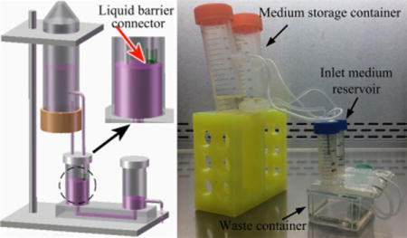
TOC image
We present a micropump enhanced with siphon-based autofill function to realize autonomous and continuous perfusion with steady flow over extended time.
Introduction
Delivery of continuous and steady medium flow with accurate flow control is essential for 3D cell/tissue culture inside microfluidic devices, especially for recent organ-on-a-chip applications [1, 2]. In order to generate constant and well-controlled flow in a microfluidic system, external active macropumps such as syringe pumps [3], electrokinetic pumps [4], and compressed air pumps [5] are commonly utilized. However, these types of bulky pumping equipment usually require external electrical power supplies and the corresponding control units, which make them unsuitable for POCT applications that are typically portable diagnostic and monitoring devices [6]. For cell/tissue culture applications, since their culturing microenvironments need to be well maintained at 37°C in 5% CO2, it is generally prohibitive since the external components of a macropump, such as electric wires or pressure control tubings, would all need to be placed into an incubator. Even though versatile on-chip active micropumps, such as membrane micropump [7], rotary micropump [8], diffuser micropump [9], ultrasonic micropump [10], electroosmotic micropump [11], electro-hydrodynamic micropump [12] and magneto-hydrodynamic micropump [13], have been developed to realize the flow operations with smaller footprints, the flow capacity is insufficient for long-term operation and they still need control signals from external MEMS actuators or transducers to initiate or stop flow, making them difficult to operate inside incubators.
To overcome these limitations, researchers have developed a number of low-cost, zero electric power consumption, and portable on-chip passive micropumps by different approaches. The pumping mechanism based on pressure difference is the most straightforward and commonly used method in various microfluidics-based applications. Examples of this category of micropumps include the hydrostatic pressure-driven micropump based on either difference in medium height or controlled liquid evaporation rate between inlet and outlet medium reservoirs [14,15], the surface tension-driven micropump based on the droplets with different sizes at inlet and outlet ports [16], the osmotic pressure-driven micropump based on the solutions with different concentrations [17], as well as the gas pressure difference-based micropump based on pre-vacuumed PDMS as negative pressure or gas generation through chemical reactions as positive pressure [18,19]. Among these pumping mechanisms, each has its own pros and cons. In particular, the pressure difference-driven micropump could not regulate the flow rate well, and is only suitable for short-term use. Therefore, it is unsuited to applications that need long-term stable flows, like 3D cell/tissue culture in microfluidic device. Another promising pumping mechanism takes advantage of capillary force by using either paper or textile wicking as thread pump [20,21], or by designing a branched microstructure with different dimensions close to the outlet [22], which can generate the adjustable flow rates inside microfluidic channels. Due to the relatively small capillary force, the micropump based on this mechanism is not suitable for maintaining a high flow rate. Recently, another pumping concept by applying finger force on a deformable chamber [23] or pumping lid [24] was reported, which can generate the flexible flow rate control by the design of the pressure chamber or pumping lid with different dimensions or geometries. However, this pumping mechanism is still difficult to operate inside an incubator with a closed environment for a long time. The siphon effect has been widely utilized as siphon valves in centrifugal microfluidic platforms [25], but is rarely utilized as the microfluidics-based micropump.
Here, we present a flexible hydrostatic pressure-driven passive micropump enhanced with siphon-based autofill function, which can realize autonomous and continuous fluid perfusion inside the microfluidic chip with accurately controlled steady flow for a long period of time. Compared with the previous on-chip passive micropumps, this micropump exhibits multiple beneficial features on a single platform, including: (1) small size (13×5×6 cm3) and lightweight (60 g) of single disassembled system for portability; (2) simple system setup with easily acquired components and ease of operation without peripheral equipment; (3) autofill function enabling long-term perfusion with constant flow rate; (4) flow rate driven by hydrostatic pressure drop can be easily and accurately adjusted; and, (5) multiplexed flow conditions are possible with high controllability and flexibility. As a model application that takes advantage of these capabilities, a microvascular network formation model under the stimulus of interstitial flow was established to demonstrate the effectiveness and power of this enhanced micropump.
Materials & Methods
Platform setup
Figure 1 shows the schematic diagram of whole platform setup, and its assembly process is presented in a movie clip (ESI† Movie S1). A microfluidic chip, attached with bottomless plastic vials as medium reservoirs at both inlet and outlet ports is mounted on the object stage of a clamping platform. To enable versatile applications, microfluidic chips with different microchannel geometries and dimensions can be integrated into this platform. A tightly sealed conical tube with large volume (e.g. 50 mL) is fixed by the clamping platform positioned above the inlet medium reservoir (IMR), which can function as the medium storage container (MSC). Two plastic tubings with different heights can function as siphons to establish the interconnection between MSC and IMR. Briefly, these tubings can be connected with conical tube at different location by using a needle and sealed by hot glue or epoxy. To ensure there is enough pressure to induce flow inside the low siphon to activate the siphoning effect, the top end of the straight low siphon should be positioned as close to the bottom of the MSC as possible. For the bent high siphon, its top end can be placed at any position above the top end of the low siphon, and its bottom end should be positioned at the desired height to maintain the desired constant liquid level inside the IMR. To control the liquid level at the outlet medium reservoir (OMR), another tube can be inserted into the OMR at the desired height to divert the redundant medium into a waste liquid container. Therefore, a constant hydrostatic pressure drop between IMR and OMR can be generated to supply the steady flow inside the microfluidic chip, which also enables the long-term perfusion with the assistance of siphon-based autofill function.
Fig. 1.

Schematic diagram showing the platform setup of the hydrostatic pressure-driven passive micropump enhanced with siphon-based autofill function.
Principle of siphon-based autofill function
A siphon can be explained as a tube or pipe that allows liquid to flow from the higher level to the lower level without using pumps, which can be mathematically described by Bernoulli’s equation. The Bernoulli equation is an approximate relation between pressure, velocity, and elevation, which is only valid for incompressible flow and is expressed as:
| (1) |
where V is the fluid velocity at the chosen point along the streamline, g is the gravitational acceleration constant, h is the elevation of the point above a reference plane, with the positive direction pointing upward, P is the pressure at the chosen point, ρ is the density of the fluid at all points along the streamline, and the value of constant will be the same at any point along a given steady state streamline with non-dissipative flowing fluid in the same fluid systems. For both the low siphon and the high siphon, their top ends are set as the starting points of the siphon and their corresponding horizontal planes are the reference elevations. As shown in Fig. 2a, applying Bernoulli’s equation to the liquid surface inside MSC based on the reference elevation of the low siphon (RELS):
| (2) |
where VC is the falling speed of liquid surface inside MSC, hLA is the distance between the liquid surface inside MSC and the RELS, and Pur is the air pressure inside MSC.
Fig. 2.

Schematic diagram showing the working principle of siphon-based autofill function. (a) Liquid from both siphons during the initial filling process. (b) No liquid inside the high siphon due to the decreased pressure inside the MSC. (c) Cavitation inside the high siphon and air bubbles appearing inside the MSC. (d) No liquid inside both siphons and no air bubble appearing inside the MSC when the liquid level inside the IMR reached to the DPHS. (e) Activation of refilling process when liquid level inside the IMR dropping below the DPHS. (f) Autonomous repetition of refilling process.
Compared with the large volume inside MSC, its volume change during each refilling loop is very limited. Therefore, by assuming that MSC is infinite, the falling speed of its liquid surface can be set to zero (VC=0). Equation (2) can be further simplified as:
| (3) |
Applying Bernoulli’s equation to the draining point of the low siphon (DPLS) at the height of -hLB relative to RELS before submerging into medium inside IMR (Fig. 2a):
| (4) |
where VL is the flow velocity at the DPLS, and Patm is the atmospheric pressure. After submerging, applying Bernoulli’s equation to the low siphon positioned at the liquid surface inside IMR (Fig. 2b):
| (5) |
where VR is the flow velocity inside the low siphon at the position of liquid surface inside the IMR, and -hLM is the distance of liquid surface inside IMR below the RELS.
Since the siphon is a single system, the constant in all of the above equations is the same. Setting equation 3 and 4 equal to each other gives:
| (6) |
Solving for VL:
| (7) |
Similarly, the velocity VS at the draining point of the high siphon (DPHS) based on the reference elevation of the high siphon (REHS) can be represented as:
| (8) |
where hSA is the distance of liquid surface relative to the REHS inside the MSC, and hSB is the distance between the REHS and DPHS. Therefore, the velocity difference between the DPLS and the DPHS before submerging can be expressed as:
| (9) |
where d is the distance between the DPHS and DPLS. Similarly, their velocity difference after submerging can be represented as:
| (10) |
where Δd is the distance between the DPHS and the liquid surface inside IMR.
In order to activate the siphoning effect, there must be flow coming from the low siphon first to perfuse IMR (i.e. VL>0). From equation 7, the following pressure relationship should be satisfied:
| (11) |
It can be easily realized by increasing the length of the low siphon (hLB) through the flexible height adjustment of the clamping platform. With the drop of liquid level inside the MSC, its inside pressure P’ur will decrease accordingly. According to equation 8, when the liquid level inside the MSC drops to h’SA relative to the REHS, it satisfies the following pressure relationship:
| (12) |
At this moment, the velocity VS at DPHS will become zero, as shown in Fig. 2b. However, there still will be flow coming from the low siphon at the velocity of to raise the liquid level inside the IMR continuously as long as the height difference Δd exists.
As the liquid level inside the MSC drops gradually, the inside pressure P’ur will decrease continuously. Under the effect of atmospheric pressure, air will be pushed into the high siphon from its draining point to induce cavitation. Simultaneously, air bubbles will appear within the MSC, which can increase the inside pressure P’’ur accordingly (Fig. 2c). As a result, the liquid level inside the IMR will rise continuously until it is flush with the DPHS to block the air supplementation (Fig. 2d). Thus, the DPHS will determine the height of liquid level inside the IMR, which can be flexibly adjusted by changing its position. With the slow medium perfusion into the microfluidic channel through the inlet port, the liquid level inside the IMR will decrease accordingly. Once it is below the DPHS, air will be pushed into MSC again to re-adjust the liquid level height to the DPHS (Fig. 2e). The whole process repeats itself autonomously (Fig. 2f), and finally realizes the siphon-based autofill function.
To better understand this principle, the siphon-based autofill function can be simulated into a simplified electric circuit model. For the air supplementation into the MSC during the cavitation process from the high siphon, it can be analogous to the capacitor charging process, as shown in Fig. 3a. Since the air volume inside the MSC is always changing, it can be treated as a variable capacitor C(P’’ur). The switch represents whether there is air supplementation into the MSC, which is determined by the distance between the liquid level inside the IMR and the DPHS. Once this distance becomes zero, it corresponds to the switch-off. The negative pressure P’ur inside MSC can be treated as the reference voltage V(P’ur) at the time when the first cavitation process initiates, and the atmospheric pressure at the DPHS is considered as the DC voltage source V(atm). After power consumption by the resistance of R(hSB) along the high siphon and R(h’SA) through the medium inside the IMR, if the applied voltage is still higher than V(P’ur), C(P’’ur) will be charged which corresponds to the generation of air bubbles inside the MSC. For the IMR during the auto-filling process with liquid through the low siphon, since the liquid level inside the MSC and IMR almost has no change during the adjacent refilling processes, it can be treated as the reference voltage V(h’’LA+h’LM), as shown in Fig. 3b. As the variable capacitor C(P’’ur) charges, once the total amount of applied voltage is higher than the voltage of V(atm) that represents the atmospheric pressure positioned at the liquid level inside the IMR, the fixed capacitor C(IMR) will be charged continuously until the switch during the cavitation process is off. Due to the fixed electrical potential difference between the input voltage V(IMR) of the fixed capacitor C(IMR) and output voltage V(OMR), the current passing through the resistance of microfluidic channel Rchannel is constant, which corresponds to the steady flow inside the microfluidic channel.
Fig. 3.
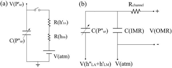
Electric-fluidic circuit analogy of siphon-based autofill function. (a) Electric circuit of variable capacitor charging process to simulate the air supplementation inside the MSC during the refilling process. (b) Electric circuit of fixed capacitor charging process to simulate the liquid filling inside the IMR during the auto-filling process.
Sensitivity analysis of autofill function
Theoretically, during each autofill process, once the liquid surface inside the IMR is below the DPHS, the autofill function will be activated immediately. However, in the practical applications, when the liquid surface inside the IMR touches the DPHS, a liquid column with certain height hw will usually appear inside the high siphon due to either the capillary effect of the high siphon or pressure fluctuation inside MSC (Fig. 4a). In this case, even though the liquid surface inside the IMR drops to the level below the DPHS, there is still no air bubble appeared inside MSC to supplement the pressure, which means the autofill function will be invalid. Therefore in order to restart the autofill function, the pressure PMSC inside the MSC must be further reduced to withdraw the liquid column from the high siphon, which could only be realized by the drop of liquid level inside the IMR. Suppose when the liquid surface inside the IMR drops to the distance of h’LW relative to the RELS (Fig. 4b), the liquid column can be removed to restart the autofill function again. The pressure change inside the MSC during the reactivation stage can be represented as:
| (13) |
This pressure change ΔPMSC should at least offset the extra pressure induced by the liquid column inside the high siphon. Therefore, the following pressure relationship should be satisfied:
| (14) |
This indicates that the liquid surface inside the IMR must drop a distance of at least hw relative to the DPHS to restart the autofill function. Since medium perfusion into the microfluidic chip through the inlet port is very slow, it will take quite a long time to restart the autofill function with low sensitivity. Therefore, to increase the sensitivity of the autofill function, a liquid column inside the high siphon must be avoided (i.e. hw=0).
Fig. 4.
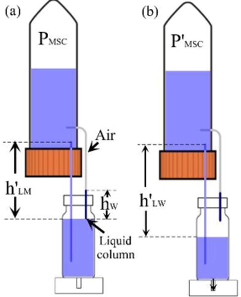
Schematic diagram showing the sensitivity analysis of autofill function. (a) Liquid column formation inside the high siphon to block the air supplementation into the MSC. (b) Low sensitivity of liquid level drop inside the IMR through a certain distance to reactivate the autofill function.
Liquid barrier connector fabrication and operation optimization
In order to completely eliminate the formation of the liquid column inside the high siphon, a homemade liquid barrier connector (LBC) was fabricated and installed at the DPHS, as shown in Fig. 5a. Briefly, a gas permeable/liquid impermeable PTFE film with the pore size of 1μm was hermetically sealed at one side of the connector, and the other side was tightly connected with the high siphon. The fabrication procedure of the LBC was simple, and its assembly process and prototype were shown in a movie clip (ESI† Movie S6) and Fig. S1, respectively. First, two circular disks and the liquid barrier film were separately cut out from a 5 mm thick premade PDMS slab and a thin PTFE film by using the puncher with the diameter of 10 mm. Then, holes with the diameter of the high siphon and 4 mm were separately punched at the center of these two PDMS disks. After their plasma bonding as the housing of LBC, the punched film was glued to this housing by the highly viscous prebaked PDMS without blocking the 4 mm opening. Finally, the fully cured connector was inserted into the cap of the IMR, which could be manually moved to adjust the liquid level inside the IMR with high flexibility.
Fig. 5.
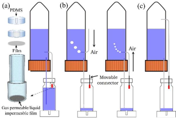
Schematic diagram showing the LBC design and operation optimization. (a) Schematic view of the LBC configuration with PDMS and gas permeable/liquid impermeable film, and its integration at the DPHS to prevent liquid column formation during the refilling process. (b) Lift up the high siphon when its top end is immersed into liquid inside MSC to eliminate liquid column formation during the initial filling process. (c) No liquid column formation during initial filling process if the top end of the high siphon is immersed into air inside the MSC.
Moreover, to further increase the sensitivity of this enhanced micropump, it is also necessary to prevent liquid column formation inside the high siphon during the initial filling process in which the medium perfusion into the IMR from the low siphon. As shown in Fig. 5b, if the top end of the high siphon is immersed into the liquid inside the MSC, the high siphon should be lifted up to prevent liquid column formation inside it until air bubbles appear inside the MSC. Then, the high siphon can be lowered and interconnected with the movable LBC. Meanwhile, air bubbles inside the MSC would become smaller and faster. Otherwise, the high siphon can be interconnected with LBC directly without inducing the liquid column during both the initial filling and the subsequent refilling process, but no air bubble will appear inside the MSC as the indicator (Fig. 5c).
Finite element simulation of interstitial flow for vasculogenesis
Finite element simulations on interstitial flow for vasculogenesis under the drive of a constant hydrostatic pressure drop were performed by COMSOL Multiphysics 4.3 (Comsol Inc., Burlington, MA, USA). The chip design for the vasculogenesis assay was similar to those described in our previous studies [14, 26]. The interstitial flow across a porous fibrin gel with low permeability of 1.5×10⁻¹³ m2 inside the tissue chamber was simulated by employing the Brinkman equation for momentum transportation. Due to the steady hydrostatic pressure drop between the IMR and OMR, the corresponding pressure drop across each tissue chamber was constant to generate the uniform interstitial flow profile, which is the biophysical cue inside the fibrin gel necessary to stimulate vasculogenesis.
Cell culture
Human endothelial colony forming cell-derived ECs (ECFC-ECs) were isolated from cord blood [27], expanded on a flask coated with 10 μg/mL fibronectin (Sigma Aldrich) in EGM-2 (Lonza), and used between passages 4-6. Human normal lung fibroblasts (NHLF) were purchased from Lonza, expanded in DMEM (Corning) containing 10% FBS (Gemini Bio), and used between passages 6-8. All cell types were grown in a 37°C/5% CO2/20% O2 incubator with 100% humidified air environment, and all experimental procedures for embedding cell/tissue into microfluidic device were performed inside a Biosafety Level 2 laminar flow hood with sterile techniques as previously described [14, 28].
Results
Effectiveness of enhanced micropump with autofill function
We first tested the effectiveness of the LBC on the sensitivity of the siphon-based autofill function. As shown in a movie clip (ESI† Movie S2), the sensitivity of autofill function without using the LBC was very low due to the liquid column formation inside the high siphon that postponed the cavitation process. The autofill function could be reactivated only if the liquid column inside the high siphon was removed with the liquid level in the IMR dropping. However, with the LBC, the autofill function could be activated immediately once the liquid level was below the liquid barrier film sealed on the connector (i.e. predefined liquid level).
In addition, the comparison experiments on the maintenance of hydrostatic pressure drop were conducted based on the micropump with and without autofill function for a microfluidic chip. Here, a long straight microchannel with the length of 45 mm and the diameter of 0.7 mm was designed in the chip. As shown in Fig. 6 and a movie clip (ESI† Movie S3), for the conventional hydrostatic pressure-driven passive micropump without autofill function, the liquid level difference between the IMR and OMR dramatically dropped, with a decreased flow rate from 0.935 mL/min to 0.0436 mL/min over around 9 min. However, for the micropump enhanced with autofill function, the liquid level inside the IMR could be steadily maintained at the height of 4 cm determined by the LBC (i.e. DPHS). Since the liquid level inside the OMR was set to be 0.5 cm, the hydrostatic pressure drop between the IMR and OMR could be steadily maintained around 3.5 cm that resulted in the average flow rate between 1.0 mL/min and 1.1 mL/min with little fluctuation. It would also persist for a considerable period of time until the liquid level inside the MSC was below the RELS (low siphon level), as shown in Fig. 6b (T=11 min). In the experiment, the average flow rate was characterized by using the gravimetric method, which was measured with an electric balance (FA1004 from Shanghai Liangping Instrument Co., Ltd. with a resolution of 0.1 mg) by weighting the medium accumulated in the outlet medium reservoir driven by the micropump within a defined period of time.
Fig. 6.
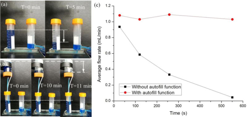
Comparison experiment to test the effectiveness of the enhanced micropump with siphon-based autofill function. (a) Decreased hydrostatic pressure drop for conventional micropump without autofill function. (b) Constant hydrostatic pressure drop for enhanced micropump with siphon-based autofill function. (c) Quantitative analysis of flow rate obtained from hydrostatic pressure-driven passive micropump with and without autofill function over time.
Based on the relative flow rate between the inlet and outlet, there were two different refilling modes, as shown in a movie clip (ESI† Movie S4). If the flow rate in low siphon was higher than the drainage from outlet tubing, the IMR would be refilled intermittently to maintain the constant liquid level determined by the LBC and air bubbles only appeared inside the MSC during the refilling process. Otherwise, the IMR would be refilled continuously and air bubbles appeared all the time. However, in this case, the liquid level inside IMR decreased over time due to the inadequate medium supply and the stable flow rate could not be generated. In both cases, regardless of the different micropump configuration, the autofill function is always effective. However, for microfluidic- based applications, the intermittent refilling mode is normally performed due to the high fluidic resistance of narrow microfluidic channel compared with the diameter of the low siphon. Thus, the constant liquid level can always be well maintained through the autofill function of enhanced micropump to realize the stable flow rate inside microfluidic chip.
Characterization of the enhanced micropump
For the hydrostatic pressure-driven passive micropump, the flow rate inside the microfluidic device was dependent on the medium height difference between the IMR and OMR, as well as the dimensions of the microfluidic channels. As shown in Fig. 7a, for the same microfluidic device integrated with the enhanced micropump, the flow rate was linearly proportional to the predefined hydrostatic pressure drop between IMR and OMR, which was determined by the DPHS and the height of drainage tubing at OMR, respectively. The small error bar range also indicated that the flow rate under certain hydrostatic pressure drop was stable as the result of the siphon-based autofill function.
Fig. 7.
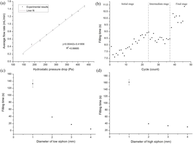
Quantitative analysis of the characteristics of enhanced micropump with autofill function. (a) Good linear relationship with small error bar range between hydrostatic pressure drop and flow rate. (b) Refilling time in each cycle slightly increased as the cycle number increased in the same refilling loop. (c) The bigger the diameter of the low siphon, the shorter the refilling time (liquid volume:1 mL). (d) The bigger the diameter of the high siphon, the shorter the refilling time (liquid volume:1 mL).
For one device in the same refilling loop, the refilling time in each circle would slightly increase as the cycle number increased, especially at the initial refilling stage, as shown in Fig. 7b. It is known that when supplementing a certain amount of air, the larger the confined space, the lower the pressure inside it. Similarly, the air volume inside MSC would increase gradually as its liquid level dropped, which resulted in the decreased flow rate at the DPLS to extend the refilling time. Specifically, the air space inside MSC was limited at the initial refilling stage (e.g. 0-24 cycles). When supplementing the air from high siphon during this stage, the pressure inside MSC would recover rapidly. As a result, the refilling time would increase as the cycle number increased with high sensitivity. When the liquid level inside MSC dropped to a certain height after several cycles (e.g. 25-37 cycles), the pressure recovery induced by the air supplement was less sensitive than that at the initial refilling stage. Then we observe that there is a plateau during the intermediate refilling stage. When the liquid level almost reached the bottom of MSC after more cycles at the final refilling stage (e.g. >38 cycles), the sensitivity was pretty low that resulted in the great variance in the refilling time.
Besides the air volume inside the MSC, the diameters of both the low siphon and the high siphon would greatly affect the refilling time. As shown in Fig. 7c, the bigger the diameter of the low siphon, the shorter the refilling time. For example, to refill the liquid volume of 1 mL, it would take an average of 132 s, 38 s, 17 s and 4.6 s for the high siphon with the same diameter of 1 mm and the low siphon with different diameter of 1 mm, 2 mm, 3 mm and 4 mm, respectively. It was because the bigger the diameter of the low siphon, the higher the liquid flow rate inside it. In addition, the faster the drop of liquid level inside the MSC, the higher the speed of bubbles coming from the high siphon. Similarly, for the low siphon with the same diameter, it would take a shorter refilling time for the high siphon with a larger diameter. As shown in Fig. 7d, to refill the liquid volume of 1 mL, it would take an average of 161 s, 39 s, 33 s and 30 s for the low siphon with the same diameter of 1 mm and the high siphon with different diameter of 1 mm, 2 mm, 3 mm and 4 mm, respectively. In contrast to the influence of the low siphon on bubble speed, the bigger the diameter of the high siphon, the slower the speed of bubbles coming from the high siphon. However, the bubble size would be much bigger for the high siphon with a larger diameter. Although different diameter of both high siphon and low siphon had large effect on the refilling time, the influence sensitivity of low siphon would be much larger than that of high siphon.
Parallel and multiplexed micropump with high flexibility
By interconnecting multiple IMRs with tubing or other components (e.g. luer connectors, etc.), two or more parallel experiments for statistical analysis with the same flow conditions can be simultaneously conducted by using only one MSC, as shown in Fig. S2. Through the connected vessels effect, the liquid volume inside multiple IMRs will be maintained at the same height level that is determined by the DPHS inside only one IMR.
Furthermore, the respective high siphon from two different MSCs could be interconnected into one common high siphon through a four-way stopcock with four different operation modes, which could be flexibly switched during either the same or different refilling loop under the same hydrostatic pressure drop (Fig. 8 and ESI† Movie S5). For the MSCs with the same liquid, after the liquid volume inside one MSC was almost empty, the other MSC could be switched on to prolong the perfusion time, which would be suitable for long-term experiments without the need to frequently refill medium in the MSC. In addition, different solutions could be selectively loaded into the IMR to the predefined liquid level, which would be beneficial for versatile applications like the response of cultured cell/tissue to different chemical reagents or drug compounds. For example, after the formation of vascularized microtumors under the continuous cell culture medium perfusion coming from one MSC, drugs inside the other MSC could be switched on and added into the cultured tissue for anti-cancer drug screening applications [29].
Fig. 8.
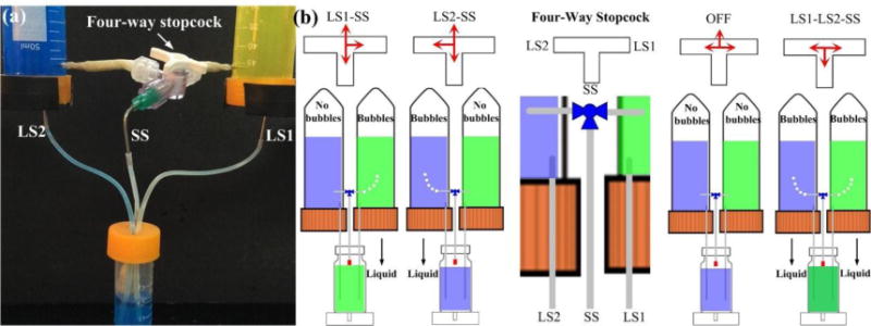
Multiplexed micropump with the integration of four-way stopcock for selective liquid perfusion into the IMR at the predefined liquid level. (a) Prototype of the multiplexed micropump. (b) Four operation modes controlled by the switch of four-way stopcock with high flexibility.
Vasculogenesis by interstitial flow with the enhanced micropump
For ease of transport and use, both the size (13×5×6 cm3) and the weight (60 g) of the single disassembled system is small, and its assembly procedure is very simple, as shown in a movie clip (ESI† Movie S6). All of the components can be easily acquired. Fig. 9a shows a prototype of the enhanced micropump with two parallel single assembled systems for in vitro vasculogenesis studies. Notably, the configuration of enhanced micropump may vary based on different microfluidic chips for specific biological applications. Here, two MSCs are placed on the ring stand above the IMRs that are fixed at the inlet ports of the microfluidic chip. Briefly, the bottom of the IMRs are immersed into the uncured PDMS and then placed on the inlet ports, which will form the solid connection after cured. The thread-to-barb fittings are utilized to establish the interconnection between the MSC and siphon, which can also be sealed with uncured PDMS. The bent stainless steel needles of predetermined height are inserted into the outlet ports, and the culture medium flowing from the outlets of the microfluidic chip is guided into an empty cell culture flask, which acts as a waste container. For microfluidic chip, three central millimeter-sized diamond tissue chambers (1 × 2 mm) with one gel loading inlet and outlet are connected with two side square cross-sectional microfluidic channels (100 ×100 μm). The microfluidic channels are further coupled in an asymmetrical design with one medium inlet and outlet, which can generate the interstitial flow across the confined gel inside tissue chamber [29].
Fig. 9.
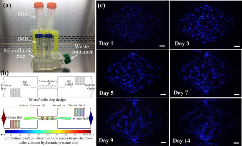
Application of the enhanced micropump system for sustaining an in vitro vasculogenesis model. (a) Prototype of system setup for tissue culture inside incubator. (b) Microfluidic chip design and simulation on the interstitial flow profile across tissue chamber for vasculogenesis. (c) Microvascular network formation inside tissue chambers throughout 14 days. Scale bar: 100 μm.
In the experiment, the hydrostatic pressure drop was steadily maintained at 10 mm H2O, and interstitial flow inside the tissue chamber was generated at a velocity of 0.31-2.55 μm/s in the horizontal direction and 2.44-19.4 μm/s in the vertical direction based on the simulation results, as shown in Fig. 9b. Under the stimulus of interstitial flow generated by the constant hydrostatic pressure drop, vascular fragments could be formed as early as day 3, and continued to develop into a capillary network through day 5 as previously described [14,28,29]. By day 7, the capillary network was lumenized and interconnected, and this could last for more than 14 days (Fig. 9c and ESI† Movie S7). Most importantly, besides the advantage of steady flow, the enhanced micropump also enabled long-term perfusion inside the incubator for up to 5 days without the need to supplement medium to the MSC or relevel the hydrostatic pressure drop between the IMR and OMR. This is 2 to 3-fold longer than our previous culture method, which needs medium change every other day [28].
Discussion
Compared with the traditional hydrostatic pressure-driven passive micropump, our enhanced micropump can provide a steady flow rate inside microfluidic devices for long periods without the need of additional complicated peripheral equipment. All the components can be easily acquired from most laboratories and replaced with high flexibility. For example, the supporting/clamping platform can be customized to hold multiple MSCs and fabricated by 3D printing technology. It also can be designed into adjustable platforms, whose height can be flexibly moved up and down to adapt multiple settings. There is no doubt that the LBC is the core component of the whole system, which will directly determine the success of autofill function and its sensitivity. To make it more reliable, the standardization of the LBC should be further improved by using standard fittings like hollow screw and nut. Furthermore, the enhanced micropump can be applied to the liquid with different hydrophilic/hydrophobic properties. If the liquid inside the IMR is hydrophilic, the PTFE films on LBC with the hydrophobic property should be utilized. Otherwise, the hydrophilic PTFE films need to be selected.
Here we have focused on a single medium reservoir module with siphon-based autofill function to maintain the high hydrostatic pressure. A further increase in the number of modules is possible for some applications that require different hydrostatic pressure drops with either the same or different liquid simultaneously. For example, for multi-organ-chip or body-on-chip applications, each organ has its own culture condition, which would communicate with each other by secreting and sensing a variety of biomolecules or metabolite. Therefore, multiple modules with either different medium types or different hydrostatic pressure drops can be placed on a single microfluidic chip to maintain the optimal condition for each organ as well as to study the organ-to-organ communications, as shown in Fig. S3.
While this enhanced micropump has many advantages, there are still some limitations. For example, although it can maintain the constant hydrostatic pressure drop to supply the steady flow rate, pulsatile flow conditions cannot be implemented directly. To solve this problem, the combination of microfluidic oscillator arrays with the enhanced micropump as the common gravity head can generate the pulsatile flow autonomously with a wide range of oscillation periods [30]. Another drawback of this micropump is that it can only provide low-pressure input to the microfluidic chips, which is only the limited hydrostatic pressure drop between the IMR and OMR. Although it’s very suitable for tissue culture and other biomedical researches, it cannot be used for applications needing high pressure or flow rate, such as droplet generation.
Conclusions
We have developed an enhanced hydrostatic pressure-driven passive micropump for versatile microfluidics-based applications, especially for cell/tissue culture. The configuration of the entire system is simple and portable, and the related components can be easily acquired. With the siphon-based autofill function, the steady flow rate with precise control can be autonomously and continuously supplied for long terms. The hydrostatic pressure drop can be flexibly adjusted by simply changing the position of the LBC inside the IMR, and the characterization results show that the refilling time will be directly influenced by the air volume inside MSC as well as the siphon diameter. With the integration of various fluidic regulators, the enhanced micropump can be further optimized to realize parallel or multiplexed medium delivery. Experimental results from a vasculogenesis assay demonstrate the effectiveness of this enhanced micropump for cell/tissue culture inside an incubator for 14 days, allowing for the development of superior organ-on-a-chip applications.
Supplementary Material
Acknowledgments
This work was supported by grants from the National Natural Science Foundation of China (No. 31600781), Science and Technology Commission of Shanghai Municipality (17JC1400200) and the Fundamental Research Funds for the Central Universities. This work was also supported by grant from the National Institutes of Health (UH3 TR00048). Dr. Hughes receives support from the Chao Family Comprehensive Cancer Center (CFCCC) through a National Cancer Institute Center Grant (P30A062203).
Footnotes
Electronic Supplementary Information (ESI) available: [details of any supplementary information available should be included here].
Author contributions
X.W and D.Z designed and implemented the platform, performed experiments, interpreted data, and wrote the manuscript. J.L, X.C and B.Y contributed to platform fabrication and data analysis. D.T.T.P and C.C.W.H contributed knowledge to project development and edited the manuscript. W.Z and A.P.L conceived the project, interpreted data, and wrote the manuscript. All authors read and approved the manuscript.
References
- 1.van Duinen V, Trietsch SJ, Joore J, Vulto P, Hankemeier T. Curr Opin Biotechnol. 2015;35:118–126. doi: 10.1016/j.copbio.2015.05.002. [DOI] [PubMed] [Google Scholar]
- 2.Bhatia SN, Ingber DE. Nat Biotechnol. 2014;32:760–772. doi: 10.1038/nbt.2989. [DOI] [PubMed] [Google Scholar]
- 3.Hung PJ, Lee PJ, Sabounchi P, Aghdam N, Lin R, Lee LP. Lab Chip. 2005;5:44–48. doi: 10.1039/b410743h. [DOI] [PubMed] [Google Scholar]
- 4.Studer V, Pepin A, Chen Y, Ajdari A. Analyst. 2004;129:944–949. doi: 10.1039/b408382m. [DOI] [PubMed] [Google Scholar]
- 5.Bong KW, Chapin SC, Pregibon DC, Baah D, FloydSmith TM, Doyle PS. Lab Chip. 2011;11:743–747. doi: 10.1039/c0lc00303d. [DOI] [PubMed] [Google Scholar]
- 6.Sia SK, Kricka LJ. Lab Chip. 2008;8:1982–1983. doi: 10.1039/b817915h. [DOI] [PubMed] [Google Scholar]
- 7.Unger MA, Chou HP, Thorsen T, Scherer A, Quake SR. Science. 2000;288:113–116. doi: 10.1126/science.288.5463.113. [DOI] [PubMed] [Google Scholar]
- 8.Chou HP, Unger MA, Quake SR. Biomed Microdevices. 2001;3:323–330. [Google Scholar]
- 9.Andersson H, van der Wijngaart W, Nilsson P, Enoksson P, Stemme G. Sens Actuat B. 2001;72:259–265. [Google Scholar]
- 10.Rife JC, Bell MI, Horwitz JS, Kabler MN, Auyeung RCY, Kim WJ. Sens Actuat A. 2000;86:135–140. [Google Scholar]
- 11.Debesset S, Hayden CJ, Dalton C, Eijkel JCT, Manz A. Lab Chip. 2004;4:396–400. doi: 10.1039/b314123c. [DOI] [PubMed] [Google Scholar]
- 12.Zeng J, Korsmeyer T. Lab Chip. 2004;4:265–277. doi: 10.1039/b403082f. [DOI] [PubMed] [Google Scholar]
- 13.Lemoff AV, Lee AP. Sens Actuat B. 2000;63:178–185. [Google Scholar]
- 14.Wang X, Phan DT, Sobrino A, George SC, Hughes CC, Lee AP. Lab Chip. 2016;16:282–290. doi: 10.1039/c5lc01050k. [DOI] [PMC free article] [PubMed] [Google Scholar]
- 15.Zimmermann M, Bentley S, Schmid H, Hunziker P, Delamarche E. Lab Chip. 2005;5:1355–1359. doi: 10.1039/b510044e. [DOI] [PubMed] [Google Scholar]
- 16.Walker GM, Beebe DJ. Lab Chip. 2002;2:131–134. doi: 10.1039/b204381e. [DOI] [PubMed] [Google Scholar]
- 17.Park JY, Hwang CM, Lee SH. Lab Chip. 2007;7:1673–1680. doi: 10.1039/b710777c. [DOI] [PubMed] [Google Scholar]
- 18.Liang DY, Tentori AM, Dimov IK, Lee LP. Biomicrofluidics. 2011;5:024108. doi: 10.1063/1.3584003. [DOI] [PMC free article] [PubMed] [Google Scholar]
- 19.Qin L, Vermesh O, Shi Q, Heath JR. Lab Chip. 2009;9:2016–2020. doi: 10.1039/b821247c. [DOI] [PMC free article] [PubMed] [Google Scholar]
- 20.Kokalj T, Park Y, Vencelj M, Jenko MM, Lee LP. Lab Chip. 14:4329–4333. doi: 10.1039/c4lc00920g. [DOI] [PubMed] [Google Scholar]
- 21.Jeong GS, Oh J, Kim SB, Dokmeci MR, Bae H, Lee SH, Khademhosseini A. Lab Chip. 14:4213–4219. doi: 10.1039/c4lc00510d. [DOI] [PubMed] [Google Scholar]
- 22.Zimmermann M, Schmid H, Hunziker P, Delamarche E. Lab Chip. 2007;7:119–125. doi: 10.1039/b609813d. [DOI] [PubMed] [Google Scholar]
- 23.Iwai K, Shih KC, Lin X, Brubaker TA, Sochol RD, Lin L. Lab Chip. 2014;14:3790–3799. doi: 10.1039/c4lc00500g. [DOI] [PubMed] [Google Scholar]
- 24.Begolo S, Zhukov DV, Selck DA, Li L, Ismagilov RF. Lab Chip. 2014;14:4616–4628. doi: 10.1039/c4lc00910j. [DOI] [PMC free article] [PubMed] [Google Scholar]
- 25.Siegrist J, Gorkin R, Clime L, Roy E, Peytavi R, Kido H, Bergeron M, Veres T, Madou M. Microfluid Nanofluid. 2010;9:55–63. [Google Scholar]
- 26.Wang X, Phan DT, Zhao D, George SC, Hughes CC, Lee AP. Lab Chip. 2016;16:868–876. doi: 10.1039/c5lc01563d. [DOI] [PMC free article] [PubMed] [Google Scholar]
- 27.Chen X, Aledia AS, Popson SA, Him L, Hughes CC, George SC. Tissue Eng A. 2010;16:585–594. doi: 10.1089/ten.tea.2009.0491. [DOI] [PMC free article] [PubMed] [Google Scholar]
- 28.Hsu YH, Moya ML, Hughes CC, George SC, Lee AP. Lab Chip. 2013;13:81–89. doi: 10.1039/c2lc40787f. [DOI] [PMC free article] [PubMed] [Google Scholar]
- 29.Phan DT, Wang X, Craver BM, Sobrino A, Zhao D, Chen JC, Lee LY, George SC, Lee AP, Hughes CC. Lab Chip. 2017;17:511–520. doi: 10.1039/c6lc01422d. [DOI] [PMC free article] [PubMed] [Google Scholar]
- 30.Kim S-J, Yokokawa R, Cai Lesher-Perez S, Takayama S. Nat Commun. 2015;6:7301. doi: 10.1038/ncomms8301. [DOI] [PMC free article] [PubMed] [Google Scholar]
Associated Data
This section collects any data citations, data availability statements, or supplementary materials included in this article.


