 Bio-nanomaterials offer promise in the field of tissue engineering.
Abstract
Bio-nanomaterials offer promise in the field of tissue engineering. Specifically, environmental cues such as the material chemistry, topography and rigidity of the surface to which cells adhere to, can alter and dictate cell shape, proliferation, migration, and gene expression. How deeply each factor (topographical, chemical and mechanical) drives cell response remains incompletely understood. To illustrate cell sensitivities to different factors, we herein present ZnO nanorods (ZnO-Nrds) coated on glass and polydimethylsiloxane (PDMS) substrates and analyzed cell viability and proliferation. The work presented here shows a clear response of various cell lines (mouse embryonic fibroblasts 3T3, human cervix carcinoma HeLa and human osteoblast-like cells MG63) to the rigidity of the underlying surface. The chemical counterpart, given by the presence of ZnO-Nrds, strongly reduced the cell viability of all cell lines. However, the substrate underlying the ZnO coating impacted cell spreading and viability. The substrates exhibited a better ability to neglect cell attachment and proliferation with the ZnO coating and pro-apoptoticity specifically with the PDMS as the underlying substrate which exhibited a “softer” environment with respect to a glass substrate. The results also revealed that the few cells that adhered to the ZnO-Nrds on PDMS and glass showed a rounded morphology. On the basis of these observations, we can correlate common features of phenomenological cell response to chemotactic and durotactic cues. The work presented herein reinforces the response of cells to changes in substrate rigidity. These observations provide a foundation for a potentially promising approach to decrease cell adhesion and thus as an optimal substrate for different applications such as prosthesis design, tissue engineering, anti-bio fouling materials and diagnostics.
Introduction
The ability to control cell behaviour has increasingly been recognized as a crucial issue for implanted biomaterial devices such as biosensors and suitable biocompatible implants.1,2 As the cell–material interface is one of the first steps of communication in the inflammatory response to a foreign biomaterial body, a surface which inhibits adhesion and function may operate in modulating its response. Material-induced cell responses would allow, in fact, to instruct cells with specific commands eventually affecting cell fate and functions.3 Previous studies have shown that basic cell functions such as adhesion, proliferation, and morphology are extremely sensitive to the surrounding material features including mechanical, biochemical and topographical cues of the extracellular microenvironment.4,5 In particular, mechanical guidance, typically known as mechano- or durotaxis, is recognized to drive processes in development, cancer, and wound healing coordinating cells in their collective migration.6,7 Substrate rigidity can be modulated in order to mimic the extracellular matrix in the cell environment.8,9 Varying the stiffness gradient and investigating the interactive effect on mechanotaxis would supply specifics regarding the mechanical principle of cell motility and provide important guidelines for the design of biomaterials capable of manipulating the migration and localization of cells.4
In recent years, nanostructured materials have attracted a huge growing interest in the field of tissue engineering and biomaterials as they can direct cell response solely by their controllable geometric cues.10–12 Key observations have shown that nanostructured materials obtained by nanoparticle assembling (i.e. bottom-up approach) such as zinc oxide nanorods (ZnO-Nrds) hold great promise in a number of biomedical applications for future clinical applications and applications in medical devices.13–17 In fact the antifouling properties of ZnO-Nrds show great potential for modulating the cell response around implanted biomaterials. Most of the studies reported have shown toxicity interrelated with the various morphologies of ZnO nanoparticles and nanorods suggesting that these nanomaterials could be used as an adhesion-resistant biomaterial,15,18,19 as reported in Table S1.† The cytotoxicity of ZnO has resulted to be cell type-specific and dependent on the shape and size of the material. For example, zinc oxide was toxic for neuroblastoma cells,14 macrophages,20 and vascular endothelial cells21 while it was non-toxic to human dermal fibroblasts22 and T-cells.23 Moreover, the size and shape of the ZnO nanostructures have been shown to be a critical parameter for the cytotoxicity of the biomaterial.14–28 However, of great relevance, very little attention has been paid to surface mechanical property alterations. Moreover the exact toxicity mechanism is not completely understood and still controversial, therefore new insights into the complexity and roles of ZnO in cytotoxicity may derive from considering the mechanotactic properties of the substrate. In this study, we hypothesized that adhesion and apoptoticity of cells are dependent on the mechanical and biochemical properties of the substrate. To test this we coated ZnO-Nrds on PDMS and glass substrates by using a hydrothermal synthesis process.13,17 We show that the mechanical properties of the substrate can significantly influence the pro-apoptotic behaviour of different cell lines. In addition the ZnO-Nrd coated substrates displayed a wide range of mechanical and wettable properties whereas their chemical and topological properties remained constant. The responses of 3T3 fibroblasts, HeLa cells, and MG63 osteoblast cells, in terms of proliferation and morphology to the nano-patterned ZnO-Nrds were evaluated. Overall, the results showed that significantly lower adhesion was found on ZnO-Nrd coated substrates, with marked differences in cell morphogenesis and proliferation that depended on the stiffness and wettability of the substrate. Our work suggests that soft substrates are more suitable for reducing cell adhesion when compared with rigid materials. To the best of our knowledge, this is the first time that the mechanical properties of the substrate underlying a coating is shown to influence cell adhesion.
This study was performed for the purpose of producing and investigating material design strategies for mechano biomaterials in vitro cell-interaction in order to further minimize adhesion of cells. We have focused on the microenvironment, specifically the chemical, topographical and mechanical properties, to improve pro-apoptotic means. The further understanding of cell–material crosstalk may remedy the unmet need for strategies to control cell adhesion, and find significant application in prosthesis design, tissue engineering and diagnostics.
Experimental
ZnO nanorod synthesis
ZnO-Nrds were obtained using a two step synthesis process, as previously reported.13,17 First, a ZnO seed layer was prepared by mixing an equimolar ethanol solution 30 mM zinc acetate dehydrate (Sigma Aldrich, St Louis, MO) with NaOH (Sigma Aldrich, St Louis, MO) at 60 °C for 1 h. Next, the seed layer was spin-coated onto the substrates (PDMS and microscope slides, Corning, Inc., Lowell, MA) and annealed at 150 °C for 20 min, to ensure particle adhesion onto the substrate surface, several times. The growth of nanorods was carried out by suspending the substrates in 100 ml of an equimolar aqueous solution of zinc nitrate hexahydrate and hexamethylenetetramine (HMTA) (25 mM) at 90 °C for a pre-determined time from 0.5 h to 5 h, depending on the desired length of nanorods. To arrest the nanorod growth, the substrates were removed from the solution and rinsed with a copious amount of de-ionized water and dried in air at room temperature (RT). Each substrate was thoroughly cleaned in 70% ethanol and deionized water and exposed to UV light prior to characterization or cell culture experiments.
Morphological characterization
Scanning electron microscope (SEM) images of the samples were recorded using a Carl Zeiss Auriga40 Crossbeam™ instrument at magnification in a high-vacuum and high-resolution acquisition mode, equipped with a Gemini column and an integrated high efficiency In-lens SE (secondary electrons) detector. Typically, the images were acquired at low accelerating voltages (less than 5 kV) using short exposure times. Samples were fixed to aluminum specimen mounts with double coated carbon tape and sputter coated with a 15 nm Au layer prior to imaging.
Atomic Force Microscopy (AFM) (Nano Scope IIIa, Multimode, Veeco, Santa Barbara, CA) in tapping mode was used for deriving the surface roughness profile and for imaging. Standard tapping mode silicon cantilevers of “BS-Tap300” with a spring constant of 40 N m–1 and a resonance frequency of 300 kHz were used under ambient conditions. The radius of the curvature of the atomic force microscope tips was nominally less than 10 nm. A scan rate of 0.3–1 Hz was employed at a resolution of 512 pixels per line. Surface roughness measurement (Rrms), defined as the standard deviation of the elevation, was determined from 2 μm × 2 μm scans and is the average of at least four images scanned at different locations on the sample surface. Images were processed with the ImageJ software. AFM was also used to find nano-hardness and material behaviour under loading and unloading conditions during the nanoindentation test for ZnO-Nrds coated on glass and PDMS substrates. Nanoindentation measurements were performed by using torsional harmonic cantilevers with a resonance frequency of 70 kHz (HarmoniX Probes, Veeco Instruments), in AFM HarmoniX mode, using the Multimode system from Veeco Inc. (Santa Barbara, CA). The HarmoniX mode was used to discriminate the different elastic behaviours of the ZnO-Nrds coated on the glass and PDMS surfaces. The amplitude and deflection sensitivities of the HarmoniX probe were calibrated performing force curves on the surface of a silicon substrate. The sensitivities were measured by fitting the approach curves with a linear model. Then, the elastic constant of the cantilever was determined via the thermal tune method (k = 1.118 N m–1). The amplitude set point was set to 250 mV to measure the interaction between the tip and the surface plotted in the force vs. time curve. The nanoindentation test was done at 4 different locations of each sample in order to collect accurate and repeatable data.
X-ray photoelectron spectroscopy (XPS) analyses were carried out by using an Escalab 250Xi (Thermo Fisher Scientific Ltd, UK) equipped with a monochromatized Al Kα source, electromagnetic lenses and a 6-channeltron detector for spectroscopy. Acquired spectroscopic data were processed by using the Avantage v.5 software.
Surface contact angle measurement
Surface hydrophobicity of the samples was determined by measuring the water contact angle (CA) using an OCA 20 contact angle system (Data Physics Instrument GmbH, Germany) at ambient temperature. An average contact angle value was obtained by measuring the CA at five different positions of the same pattern. Using the contact angle measurement system, the critical surface tension and relative polar-dispersive components of surface free energy were evaluated using the Owens–Wendt–Rabel–Kaelble (OWRK) method. The liquids having diverse polar (γp) and dispersive (γd) surface energy components such as water (γsv = 72.10 mN m–1, γp = 52.20 mN m–1, γd = 19.90 mN m–1) and diiodomethane (Aldrich, density = 3.325, surface energy (γsv) = 50.8 mN m–1 (γd = 48.5, γp = 2.3)) were used in the Owens–Wendt–Ravel–Kaelble (OWRK) approach.
The method assumes that the surface energy, γ12, of two phases in close contact can be calculated from the surface energies of the individual phases, γ1 and γ2, as follows: with γxd and γxp being the dispersive and the polar contributions to the surface energy, respectively.
Cell cultures
Mouse embryonic fibroblasts (3T3), human cervix carcinoma (HeLa) and human osteoblast-like cells (MG63) were purchased from the ATTC. Tissue culture media and serum were purchased from Sigma-Aldrich. All cell lines were maintained in DMEM medium supplemented with FBS (10%), 100 units per mL penicillin, 100 μg ml–1 streptomycin and 2 mM l-glutamine, and sodium pyruvate (5%). Cells were grown in a humidified incubator at 37 °C, with 5% CO2 and 95% relative humidity.
Viability evaluation
The viability of 3T3 fibroblasts, HeLa cells and MG63 osteoblasts was assayed by using the 3-[4,5-dimethylthiazol-2-yl]-2,5-diphenyl tetrazolium bromide (MTT) survival tests in accordance with manufacturer's instructions (Sigma-Aldrich). Briefly, cells were seeded on uncoated/coated ZnO-Nrd glass and uncoated/coated ZnO-Nrd PDMS (50 000 cells per mL, approximately 500 cells per mm2) in 24-well flat bottom culture plates, and incubated at 37 °C in 5% CO2, 95% relative humidity for 24, 48, and 72 hours. Untreated samples were used as the control groups.
After 24, 48, and 72 hours of incubation, the cultures were removed from the incubator and the MTT solution was added in an amount equal to 10% of the culture volume. Subsequently cultures were incubated for 3 hours. Following this incubation period, the cultures were removed from the incubator and the resulting MTT formazan crystals were dissolved in acidified isopropanol solution to an equal culture volume. The plates were read within 1 hour after adding the acidified isopropanol solution. Cell viability was detected by measuring the absorbance of cell culture broth spectrophotometrically at a wavelength of 570 nm with background subtraction at 690 nm. The percentage viability is expressed as the relative growth rate (RGR) by the following equation: where Dsample and Dcontrol are the absorbances of the sample and the negative control. Representative measurements of three distinct sets of data have been reported (Student's t-test, P < 0.05).
The apoptosis evaluation was performed using Annexin V/Propidium iodate assay (Abcam) and Hoechst 33342 (Sigma-Aldrich) staining. Briefly, 3T3 fibroblasts, HeLa cells and MG63 osteoblasts were seeded on uncoated/coated ZnO-Nrd glass and uncoated/coated ZnO-Nrd PDMS (50 000 cells per mL, approximately 500 cells per mm2) and incubated at 37 °C in 5% CO2, 95% relative humidity for 24 hours. The cells seeded on the samples were washed with binding buffer 1× (10 mM HEPES, 140 mM NaCl, 2.5 mM CaCl2, pH 7.4) and 5 μL of Annexin V-FITC (AnV-FITC,) and 5 μL of propidium iodate (PI, 50 μg mL–1) were subsequently added. After 5 minutes of incubation in the dark at RT, the cells were visualized under a fluorescence microscope BX61 (Olympus). The percentage of total apoptotic cells is determined by the following equation:
Ten different fields were randomly selected for counting 100 cells. Representative measurements of three distinct sets of data have been reported (Student's t-test, P < 0.05).
In addition, apoptosis was investigated by staining the cells with Hoechst 33342 (Sigma-Aldrich). The cells seeded on the samples were washed with PBS 1× and then fixed in PBS containing 3.5% formaldehyde for 2 hours at RT. The fixed cells were washed with PBS 1× and stained with Hoechst 33342 for 1 hour at RT. The Hoechst-stained nuclei were visualized using a fluorescence microscope BX61 (Olympus).
Cell morphology
The cell morphology and cell spreading of 3T3 fibroblasts, HeLa cells and MG63 osteoblasts were evaluated by confocal laser scanning microscopy (CLSM) and SEM. All cell lines tested were seeded on uncoated/coated ZnO-Nrd glass and uncoated/coated ZnO-Nrd PDMS at 50 000 cells per mL (approximately 500 cells per mm2 of substrate) in complete culture media, and incubated for 24 h at 37 °C in 5% CO2, 95% relative humidity. Subsequently, the non-attached cells were removed by rinsing carefully with PBS 1× at least three times. Cytoskeleton morphology was investigated by cell staining with phalloidin-TRITC at a final concentration of 1 mg mL–1 (Sigma-Aldrich), according to the manufacturer's instructions. Fixed cells were immunostained for vinculin and stained for actin and the nucleus. Briefly, the cells were washed with PBS, fixed with 3.7% formaldehyde for 30 min, and permeabilized with 1% Triton™-X-100 PBS for 10 min and washed again in PBS 1×. Actin was stained with 25 μl phalloidin solution per 1 cm2 area for 40 minutes at RT and the nucleus was stained with DAPI (Sigma-Aldrich). Subsequently, the cells were washed several times with PBS to remove the unbound phalloidin conjugate and viewed with a Leica confocal scanning system mounted into a Leica TCS SP5, equipped with a 40× (NA 1.30, WD 0.24 mm) and 63× oil immersion objective (NA 1.4 WD, 0.14 mm) with a spatial resolution of approximately 200 nm in x–y and 100 nm in z. All images were acquired with the same contrast and brightness parameters.
Cell morphology was evaluated by SEM analysis. Briefly, the cells were fixed with 2.5% glutaraldehyde in PBS 1× for 5 minutes and post fixed with 1% osmium tetroxide for 1 hour in the dark at RT. The fixed cells were washed several times with distilled water and dehydrated in graded ethanol concentrations. Prior to SEM observation, the samples were sputter-coated with a 10 nm gold layer to make them electronically conductive and to avoid electronic charging during SEM imaging. SEM analyses were taken with a Carl Zeiss Merlin SEM equipped with a Gemini II column and a Field Emission Gun (FEG).
Results
Surface characterization of the substrates
The morphology of the ZnO-Nrd substrates was analyzed by SEM imaging. The ZnO-Nrds showed typical nanoscale honey-comb vertically-aligned arrays, with no significant difference in surface topography due to different substrates, Fig. 1A and B. The nanorods were approximately 80–100 nm in diameter, and ∼1 μm in height. Surface roughness was examined through AFM imaging. Controls (glass and PDMS without ZnO-Nrds) reported a roughness (measured by arithmetical mean deviation of the profile, Rq) value of 0.83 ± 0.54 nm and 1.70 ± 0.22 while the average roughness for ZnO-Nrds on glass was 80.23 ± 0.21 nm, and 95.2 ± 0.18 nm for ZnO-Nrds on PDMS. Interestingly, the surface roughness increased due to the presence of ZnO-Nrds but was similarly independent of the substrate used.
Fig. 1. Morphology of ZnO-Nrds on flat glass and PDMS substrates. (A) SEM image of ZnO-Nrds on PDMS indicating the upright growth of the nanorods, scale bar is 5 μm. The diameter of nanorods was ∼80–100 nm and the height was ∼1 μm. (B) AFM image of ZnO-Nrd on the glass substrate.
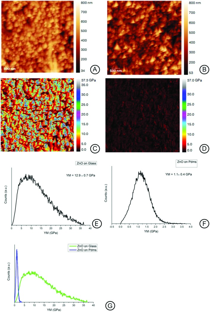
The surface mechanical properties of the ZnO-Nrd coated substrates were investigated by means of the AFM probe indentation technique.29 The Young's modulus value of the surface is shown in Fig. 2. Interestingly the elastic modulus (YM) of ZnO-Nrd coated glass was 12.9 ± 0.7 GPa, 10-fold higher than the ZnO-Nrd coated PDMS substrates (E0 = 1.1 ± 0.4 GPa), Fig. 2E–G. Uncoated PDMS samples reported a modulus of about 0.3 ± 0.8 MPa, which is more than six orders of magnitude range lower than the coated substrate while glass substrates reported a value of 72.9 ± 15 MPa (data not shown).
Fig. 2. AFM height and Young's modulus maps for ZnO-Nrd coated substrates; the maps were obtained using AFM in tapping mode (A, B), and nanoindentation (C–G). The nanoindentation maps (C, D) report the Young's modulus calculated on ZnO-Nrds on glass (C, E) and ZnO-Nrds on PDMS (D, F). It is noted that the two substrates drastically differed in modulus of a tenfold range (G).
Surface chemistry
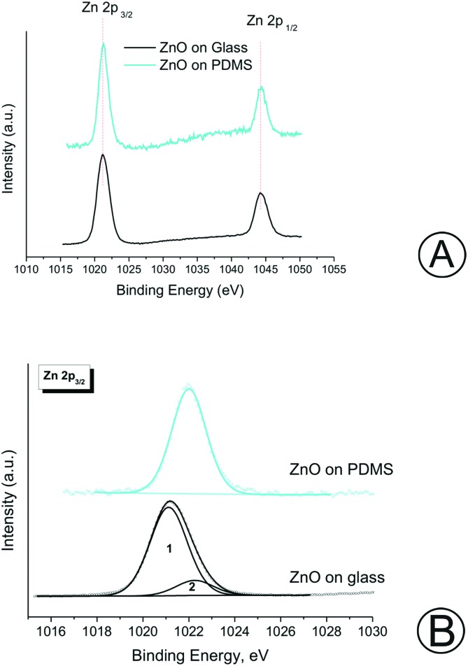
The chemical composition of the ZnO nanorods grown on the different surfaces was characterized through XPS. Fig. S1† shows the XPS survey scan of grown ZnO nanorods on the PDMS and glass substrates. The binding energy (BE) value and the atomic concentration are listed in Table S2.† It can be inferred that both samples showed the presence of zinc and oxygen.24 The obtained results evidenced that the ZnO film was uniformly distributed on both the glass and PDMS substrates. The glass substrate was characterized by a low carbon contamination as indicated by the presence of small amounts of carbonyl compounds (CO and CO2), resulting in two additional peaks at 285.0 and 289.5 eV, respectively. Instead, in the case of ZnO-Nrds deposited on the PDMS substrate, it is possible to measure the residual Si 2p and C 1s signals, corresponding to the silicon moieties originating from the PDMS substrate due to the thin ZnO-Nrd coverage. The signals of Zn due to the Auger transitions photoinduced: L2M45M45, Zn L3M45M45, L2M23M45, L3M23M45 and L3M23M45 are also shown. Fig. 3A shows the doublet Zn2+ core level peak fitting spectrum for both glass and PDMS substrates, where the two major peaks corresponding to the core level of Zn-2P3/2 and Zn-2P1/2 are clearly shown. The two distinct Zn-2p peak separation at 23. eV for glass and at 23.1 eV for PDMS confirms that Zn were in the Zn2+ oxidation state.29,30 According to the XPS results reported in Table S2,† the Zn-2p3/2 binding energy of the glass ZnO-Nrds (1022.2 eV) is greater than that of the PDMS-ZnO-Nrds (1021.9 eV), which may suggest the presence of additional Zn chemical states, therefore there may be a decrease in the number of Zn atoms bound to oxygen due to the deposition of ZnO in an oxygen-rich environment.31 Moreover, the Zn-2p3/2 peak on the ZnO-Nrd glass substrate exhibited two peaks, one peak with a binding energy of 1021.1(1) which was associated to the Zn species in ZnO.24,32–35 The other peak observed with a binding energy of 1022.2(2) was associated to the Zn species in ZnO(OH).36,37 Whereas, for the ZnO-Nrd coated PDMS, the peak fitting analysis revealed the presence of a single component, assigned to ZnO(OH). The presence of Zn2+ was also confirmed by the modified Auger parameter, defined as α′ = BE(Zn-2p) – KE(L3M45M45), that was calculated in the range of 2009.1–2009.9 eV.38 Table S2† reports also the O 1s core level for the ZnO-Nrds on glass with a peak at 531.2 eV while two distinct peaks for the ZnO-Nrds on PDMS were observed with centres at 530.7 and 532.7 eV. On the PDMS substrate, the measured peak at 530.7 eV was associated with the O2– ions on the wurtzite hexagonal structure surrounded by the Zn atoms confirming the full supplement of nearest-neighbour O2– ions. The peak at 532.7 eV could be attributed to defect level oxygen or to hydrated oxides from the growth solution.37 The binding energies of Zn-2p and O 1s confirm the fact that pure ZnO materials are formed on both glass and PDMS substrates by the association of Zn2+ and O2– ions to develop Zn–O bonds in ZnO crystals.
Fig. 3. (A) Zn-2p peak of the samples. (B) Comparison of Zn-2p3/2 spectra of the samples.
Surface wettability
As wettability also affects cellular behaviour such as cell adhesion and spreading, we investigated the surface wettability of the different substrates.39–41 Water contact angle alteration on the ZnO-Nrd coated glass and PDMS substrates are presented in Fig. 4. The glass substrate without a coating was found to be hydrophilic with a contact angle of about 47 ± 1.8°, while PDMS was, as known, hydrophobic (∼116 ± 1.3).13 Glass-ZnO-Nrd coated substrate surfaces were found to be superhydrophilic with a CA ≤ 10°. However, PDMS-ZnO-Nrds resulted in the formation of a superhydrophobic substrate with a CA ∼ 161.6 ± 0.5°.
Fig. 4. Plot of the contact angle CA of a water droplet in air showing the different wettabilities on the ZnO-Nrd coated and uncoated substrates. The ZnO-Nrd coated substrates showed extreme wettability properties: the ZnO-Nrd coated glass showed superhydrophilic properties while the ZnO-Nrd coated PDMS showed superhydrophobic properties.
The obtained surface free energies of the ZnO-Nrd coated substrates and the relationship between dispersion and polar parts of the surface free energy are presented in Table S3.† In the case of glass-ZnO-Nrd coated substrates the polar component γp is comparable to the dispersion component γd proving the presence of polar groups on the surface layer. For the PDMS-ZnO-Nrd coated substrates, we noticed a decrease within the polar fraction, indicating the poor adhesive pinning effect of the water droplet to the substrate and therefore a decrease of the attractive forces between liquid and solid phases with an increase of the contact angle.42
In vitro biological study
In order to investigate the role of substrate topography and to fabricate anti-biofouling interfaces capable of both mimicking the physiological conditions of the extracellular environment, and reducing cell adhesion we sought to examine the cytotoxic and inhibition effects of ZnO-Nrds with different cell lines.
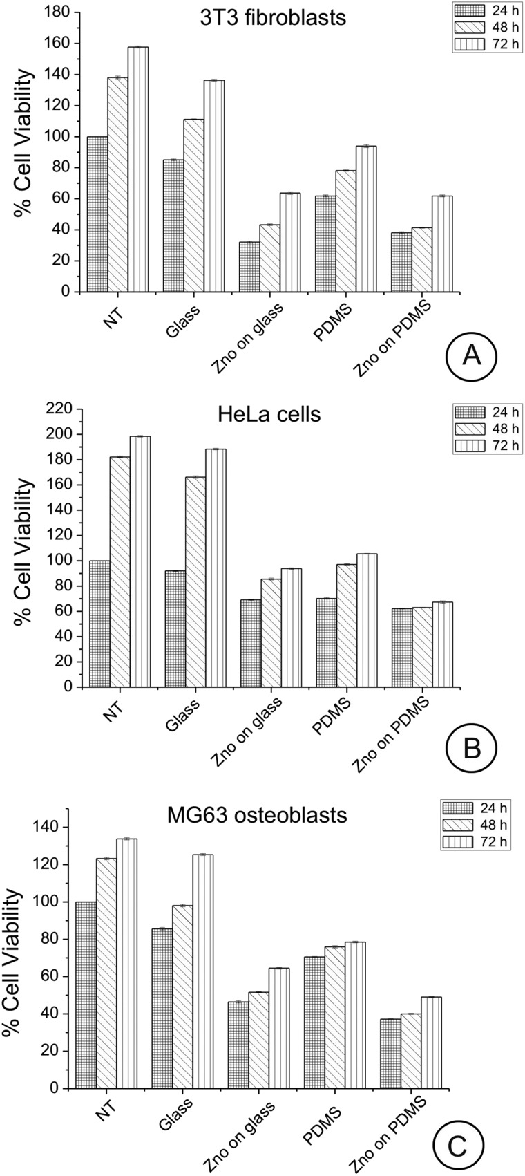
Cells were allowed to adhere for 24, 48, and 72 h on the uncoated/coated ZnO-Nrd substrates following which cell viability and apoptosis were assessed by both a metabolic MTT assay and AnV/PI staining after 24 h. Cell viability examined by the MTT assay showed no statistically significant impact after 24, 48, or 72 h exposure of cells compared with the control cells. The most significant aspect is that for both ZnO-Nrd coated glass and PDMS, after 24, 48, and 72 h of culture, the number of viable cells was reduced compared to the uncoated glass or uncoated petri dish, with the ZnO-Nrd coated PDMS supporting the lowest cell numbers (Fig. 5A–C). In more detail, at 24 h the total number of viable cells on uncoated PDMS was 72–82% compared to the control NT and glass. Moreover, at 24 h the total number of viable cells on ZnO-Nrd coated glass substrates was less than50% of the total viable number on the control NT for MG63 osteoblasts and less than 40% for 3T3 fibroblasts, while for HeLa cells it was ∼60–76%. After 72 h, the number of viable cells on the uncoated PDMS substrate was however never below about 50% compared to glass or control. However at 48 and 72 h the number of viable HeLa cells adherent on ZnO-Nrd coated substrates was less than 50% and 40% of the number of viable cells on ZnO-Nrd coated glass and PDMS, respectively. Besides when comparing ZnO-Nrd coated glass to ZnO-Nrd coated PDMS, the viability was noted to be 10% lower on the ZnO-Nrd coated PDMS for both HeLa cells and MG63 osteoblasts but not for the 3T3 fibroblasts for each 24, 48, and 72 h of experiment.
Fig. 5. MTT assay for cellular viability of 3T3 fibroblasts (A), HeLa cells (B), and MG63 osteoblasts (C) cultured for 24, 48 and 72 hours on glass, ZnO-Nrd coated glass, PDMS and ZnO-Nrds. Uncoated petri dish is used as the control (NT). Representative measurements of three distinct sets of data have been reported and no significant difference between values at different time points (Student's t-test, P < 0.05).
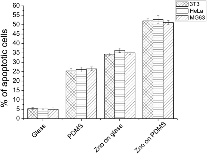
The percentage of cell apoptosis (Fig. 6) was increased when the cells were cultured on the same substrates. These results indicated that the presence of a ZnO-Nrd coating on glass or PDMS affect the cytoviability and cell proliferation. On the other hand, similar results were shown when the same cell lines were seeded on uncoated PDMS substrates.
Fig. 6. Percentage of apoptotic cells after 24 hours of culture on glass, ZnO-Nrd coated glass, PDMS and ZnO-Nrds. Representative measurements of three distinct sets of data have been reported, * indicates P-values of <0.05 for Student's t-test.
In addition, apoptotic studies on 3T3 fibroblasts, HeLa cells and MG63 osteoblasts cultured on glass, ZnO-Nrd coated glass, PDMS and ZnO-Nrd coated PDMS were performed using AnV/PI (ESI Fig. S2†) and Hoechst nuclear stain (ESI Fig. S3†). AnV/PI staining cells showed orange cells as being apoptotic, while necrotic cells were observed as being red in color due to their loss of membrane integrity.43 When the cells were seeded on uncoated glass substrates the Hoechst nuclear staining showed a whole round nucleus with a regular morphology and a bright blue fluorescence, while the cells seeded on ZnO-Nrd coated glass and uncoated/coated ZnO-Nrd PDMS displayed weak blue with nuclear fragmentation and increased chromatin condensation.
Cytoskeleton organization
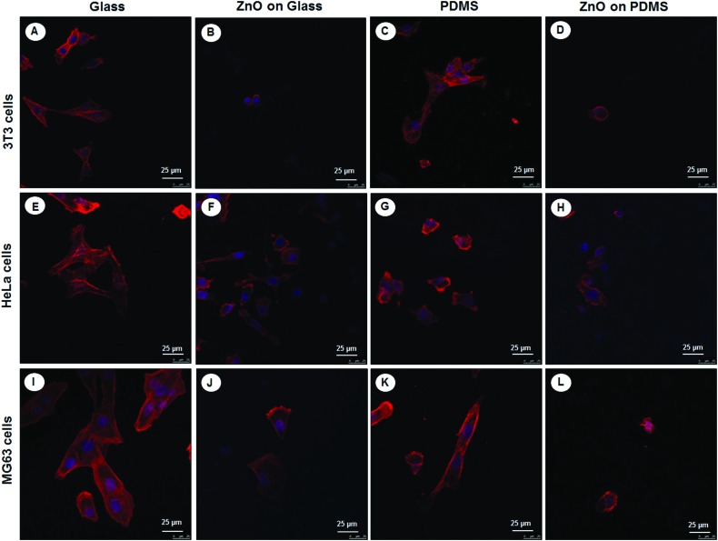
Given that cell elongation and spreading depends on attachment to the surrounding ECM and assembly of the cellular cytoskeleton, the effect of different substrates with and without ZnO-Nrds on the cytoskeleton organization of the three different cell types NIH 3T3s, HeLas, and MG63s, on glass, PDMS, glass-ZnO-Nrds and PDMS-ZnO-Nrds was examined by using immunofluorescence to monitor the changes of the cytoskeleton and cell shape.44 Cells on glass cover slips (Fig. 7A, E, and I) assembled clear stress fibers as well as a reduced adhesion to PDMS substrates (Fig. 7C, G and K). On the other hand cells grown on ZnO-Nrd substrates such as glass (Fig. 7B, F and J) or PDMS (Fig. 7D, H, and L) were characterized by lower cell density, a decreased spreading area of cells and a rounded morphology. Stress fibers were not visible in cells on ZnO-Nrds. On PDMS ZnO-Nrds a rounded and smaller morphology with a reduced cytoplasm area was noted. As cells were seeded at equivalent densities, the decrease of adherent cells on the nanorods in all three cell types is consistent with previous observations.15
Fig. 7. Confocal laser scanning images of cytoskeletal actin (red) and nuclei staining DAPI (blue) after 24 hours of incubation of 3T3 fibroblasts (A–D), HeLa cells (E–H), and MG63 osteoblasts (I–L) on glass (A, E, I), ZnO-Nrd coated glass (B, F, J), PDMS (C, G, K) and ZnO-Nrd coated PDMS (D, H, L) showing that cells do not assemble stress fibers on nanorods. The cell spreading area is greatly reduced and stress fibers are not visible in cells cultured on the nanorods. A representative result of three independent experiments is shown. Scale bars: 25 μm.
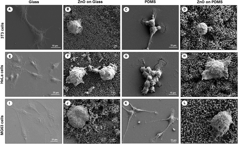
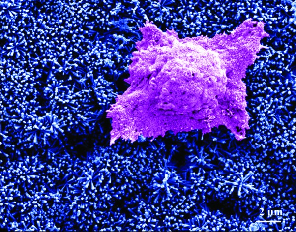
To visualize the morphological changes in the cells on different surfaces, SEM images of 3T3 fibroblasts, HeLa cells and MG63 osteoblasts seeded for 24 hours on uncoated/coated ZnO-Nrd glass substrates and uncoated/coated ZnO-Nrd PDMS samples are shown in Fig. 8. In particular, cells seeded on uncoated glass substrates exhibited elongated fibroblast-like shapes with polarized filopodia protrusions. In contrast, cells cultured on coated ZnO-Nrd glass and PDMS samples displayed typical apoptotic features, including nuclear shrinkage, and a round morphology with blebs characteristic of apoptotic cells.
Fig. 8. SEM images of NIH 3T3 fibroblasts (A–D), HeLa cells (E–H), and MG63 osteoblasts (I–L) on glass (A, E, I), ZnO-Nrd coated glass (B, F, J), PDMS (C, G, K) and ZnO-Nrd coated PDMS (D, H, L) after 24 hours of incubation. A representative result of three independent experiments is shown. Scale bars: 2 μm (B, D, F, H, J, L), 10 μm (A, C, G, K), 20 μm (E, I).
Discussion
Surface engineering of materials for biomedical implants demands awareness of various factors, including integration, biological performance, and clinical success of the implant. As a rule, cell adhesion, spreading and migration take place in a dynamic environment comprehending the mechanical topography and chemistry of a material surface. Stimuli are continuously conveyed to cells, from the underlying surface, which in turn transduce these stimuli into specific intracellular signals in response to changes in their surroundings. The effect of these cues on cell adhesion and differentiation has been the subject of a number of recent investigations and are a key point in cell adhesion according to which cells show modulated adhesion function and differentiation in response to interactions arising from the topography of the external environment.6,45,46 Nevertheless, the relative contributions of mechanical, morphological and chemical properties of a substrate in modulating diverse cellular responses are still not well understood. Therefore, work presented here focuses on the cell response to glass and PDMS substrates possessing nanotopography and different mechanotactic, chemical and surface wettability to explore the synergistic influence of topographical, mechanical and chemical alterations on various cell types.
The primary question raised by our results is why the PDMS substrate reduced adhesion compared to the glass substrates. Matrix stiffness has a well noted influence on cell adhesion and mobility.47,48 Because cells form a mechanical anchoring through the formation of focal adhesions on the substrate, the mechanical behaviour of the substrate was investigated. Young's modulus often referred to as elastic modulus or simply stiffness, is an inherent ECM asset that has a profound effect on cell spreading, morphology and function.4–6 In particular substrate stiffness has become increasingly recognized as playing a key role in many cellular processes showing not only that cells display a spreading preference for stiffer substrates but also favor migration toward stiffer regions of the substrate, a phenomenon referred to as durotaxis.6 Our data support the fact that the substrate mechanical properties can have an effect on cell viability. The adhesion of fibroblasts, cervix cancer cells and osteoblast cells was drastically decreased on the uncoated elastomer substrates as compared to that on the uncoated glass with a reduced assemblement of stress fibers. The measured elastic modulus of ZnO-Nrd coated substrate values showed an improved hardness and elastic modulus of the substrates as well as a highly reduced cell area. A major finding of this study is that under the same chemical conditions with the ZnO coating, the degree to which a cell is apoptotic is dependent on the mechanical properties of the substrate it encounters.
Beside the mechanical properties of the substrates, other factors such as hydrophobicity are likely to play a role in the cell response hindering cell spreading on the ZnO-Nrd coated substrates.49 Glass-ZnO-Nrd coated substrates were found to be superhydrophilic while PDMS-ZnO-Nrd substrates were superhydrophobic. This brusque increase of the CA and the change of the wetting regime to superhydrophobic were explained considering the solid–water interface.50 Given that the water contact angle is a physical phenomenon related to both the topological morphology of a surface and to its chemical composition, we used the Wenzel and Cassie models to explain the measured contact angles.51,52 Typically, in the wetted Wenzel state, water is in complete contact with the rough solid, therefore by increasing surface roughness, the actual CA decreases for hydrophilic materials (θ < 90°) and increases for hydrophobic materials (θ > 90°). For a rough surface composed of solid and air, according to the theory developed by Cassie et al., stable air molecules exist on a rough surface, forming a water/air/solid interface. When a rough surface comes into contact with water, air trapping in the pockets created by the rough area contributes greatly to the increase in hydrophobicity. The Cassie–Baxter contact angle (θCB) is described by the following equation:
| cos θCB = –1 + ΦS(1 + cos θ) | 1 |
where θ is the contact angle measured on the same smooth surface, and ΦS is the area fraction of the liquid–solid contact, with (1 – ΦS) being occupied by the air–liquid interface under the water droplet. Therefore, ΦS, the surface fraction occupied by the ZnO/water interface is only 9% meaning that the droplets stand on the top of the ZnO-Nrds. Regarding the possible role of the hydrophobicity/hydrophilicity of the ZnO-Nrd films, the present results showed that hydrophilic substrates were preferred for cell adhesion. Because adhesion is mediated by ECM components, it can be hypothesized to be correlated to the low surface energy. Protein absorption, which helps the adherence of cells to a surface, would be reduced, thus, cell viability was lower on the hydrophobic substrates than on the hydrophilic ones. Additionally the sharp difference between superhydrophobic and superhydrophilic ZnO-Nrd coated substrates displayed a remarkable difference in cell spreading depending on the cell type.
The toxicity of ZnO-Nrds has been recently ascribed to the dissolved zinc ions in the medium or via production of reactive oxygen species.29,53,54 However, there are still enlightening considerations that should be taken into account. A possible role of the mechanical alterations of the substrate influencing the observed decrease in cell adhesion and viability should not be excluded. Even the substrate elasticity of uncoated substrates revealed a reduction of cell adhesion of the PDMS substrate with respect to the glass substrate. The decrease in viability could not be attributed only to the surface chemistry because the chemistry of ZnO-Nrds on the glass and PDMS substrates was similar. In fact under the same chemical and topographical conditions, when comparing ZnO-Nrd coated glass to ZnO-Nrd coated PDMS, a viability reduction of 10% was proved on the ZnO-Nrd coated PDMS for both HeLa cells and MG63 osteoblasts but not for the 3T3 fibroblasts. This being the case as the cytotoxicity of ZnO is cell type-specific and dependent on the shape and size of the material as well as mechanotactically dependent.
Finally, we cannot completely rule out the role played by the nanotopography of the substrates in modulating cell adhesion and spreading. Initial adhesion of cells is a fundamental requisite to interconnect transmembrane integrins to ligands (such as fibronectin) immobilized on the surface.55 The following clustering of the integrins at the nanoscale leads to the formation of focal adhesions which allow cells to adhere to and spread on the surface.56 The lack of focal adhesion assemblement leads to the lack of cell spreading and subsequent apoptosis.57–59 Anchorage dependent cells, such as fibroblasts, HeLa and osteoblastic cells may undergo cell death due to a lack of adhesive cues, leading to apoptosis. Our results are consistent with previous observations (Table S1†) as we observed altered cell spreading dynamics on nanorod coated surfaces which did not display visible lamellipodia probably due to an inability of cells to establish strong initial adhesion to the substrate. Another prospect is cell engulfment of nanorods. Because the cells can follow the topography of the substrate, the hypothesis of penetration by nanorods cannot be excluded.20,60,61 The cell density on ZnO-Nrds was much less than that on substrates without a coating thus confirming the toxicity to cells as they dissuaded cell adhesion and reduced the cell viability. These results may indicate that decrease in cell survival in each of the cell types could possibly be related to toxicity due to a phagocytosis of the ZnO-Nrds, consistent with previous studies which accounted for the cytotoxic properties of ZnO nanomaterials on cultured cells.21,62 If the ZnO nanorods are able to perforate the cell membrane damaging the membrane integrity, the contact with cells could lead to cell death. However, what range of nanotopography is capable of reducing cell adhesion and apoptosis is yet to be determined. In any case, roughness alone is not an unrelated requirement for cell survival and growth, but it relatively requires the competitive influence of surface chemistry, wettability and durotactic properties. All these parameters are crucial in designing artificial bioimplants. The ZnO-Nrds contributed to an extreme decrease of the number of cells adhering to the substrate and chemically its cytotoxicity can be considered a capable agent in cancer therapy.63–65 However more detailed investigations are required to confirm this hypothesis.
Conclusions
In conclusion, we present here strong evidence that the substrate stiffness underlying the ZnO coating influences cell viability on ZnO nanorods. Our study enlightened interfacial aspects of the underlying substrate, indicating that the mechanical environment can strongly modulate cell behaviour and suggesting an important role in cell viability. Chemically ZnO nanorods reduced significantly adhesion inducing death in anchorage-dependent cells. Nevertheless, the appropriate elastic stiffness should be taken into account for improving the pro-apoptoticity of the substrate. Mechanically and energetically, the change of substrate rigidity of the substrate underlying the coating to a more “soft” environment, increased minimization of cell adhesion and survival. This is significant since cells intrinsically compete for the biomaterial surface and this understanding could lead to the expansion of the fundamental understanding of cellular function at the nano level and to the development of new classes of nanomaterials for improved biological performance and integration. Although the molecular mechanisms governing the process of cell–material interaction still requires attention, the manipulation of material stimuli to control cell behaviour is a key-standing goal in the design of nanostructured biomaterials for implants or antifouling stents. Care has to be taken on the development of easy-to-use and make surfaces to support cell expansion before differentiation and/or transplant back into the patient. Cell–material interactions are clearly important because they may determine the eventual success or failure of such materials. Exploring the integration of soft materials (i.e. polydimethylsiloxane) with these chemical and physical aspects will be edifying for realizing a high-quality scaffold platform. Moreover this study could open new routes in the control of cellular behaviour on biomaterial surfaces and the design of new biomaterial coatings for implants or other applications.
Conflicts of interest
There are no conflicts of interest to declare.
Supplementary Material
Acknowledgments
The authors are grateful for the support provided by the Italian Association for Cancer Research (AIRC) through the grant MFAG no. 16803.
Footnotes
†Electronic supplementary information (ESI) available. See DOI: 10.1039/c6tx00274a
References
- Anderson J. M., Rodriguez A., Chang D. T. Semin. Immunol. 2008;20(2):86–100. doi: 10.1016/j.smim.2007.11.004. [DOI] [PMC free article] [PubMed] [Google Scholar]
- Ribeiro M., Monteiro F. J., Ferraz M. P. Biomaterials. 2012;2(4):176–194. doi: 10.4161/biom.22905. [DOI] [PMC free article] [PubMed] [Google Scholar]
- Bauer S., Schmuki P., von der Mark K., Park J. Prog. Mater. Sci. 2013;58(3):261–326. [Google Scholar]
- Palamà I. E., D'Amone S. and Cortese B., Mechanical guidance of cell migration, in Nanomaterials and Regenerative, ed. Y. Lin and T. Gong, Medicine IAPCOBP Publishing, 2016. [Google Scholar]
- Cortese B., Gigli G., Riehle M. O. Adv. Funct. Mater. 2009;19(18):2961–2968. [Google Scholar]
- Lo C. M., Wang H. B., Dembo M., Wang Y. L. Biophys. J. 2000;79(1):144–152. doi: 10.1016/S0006-3495(00)76279-5. [DOI] [PMC free article] [PubMed] [Google Scholar]
- Palamà I. E., D'Amone S., Coluccia A. M. L., Biasiucci M., Gigli G. Integr. Biol. 2012;4(2):228–236. doi: 10.1039/c2ib00116k. [DOI] [PubMed] [Google Scholar]
- Hörning M., Kidoaki S., Kawano T., Yoshikawa K. Biophys. J. 2012;102(3):379–387. doi: 10.1016/j.bpj.2011.12.018. [DOI] [PMC free article] [PubMed] [Google Scholar]
- Tzvetkova-Chevolleau T., Stéphanou A., Fuard D., Ohayon J., Schiavone P., Tracqui P. Biomaterials. 2008;29(10):1541–1551. doi: 10.1016/j.biomaterials.2007.12.016. [DOI] [PubMed] [Google Scholar]
- Dalby M. J. Int. J. Nanomed. 2007;2(3):373–381. [PMC free article] [PubMed] [Google Scholar]
- Dalby M. J., Gadegaard N., Tare R. Nat. Mater. 2007;6:997–1003. doi: 10.1038/nmat2013. [DOI] [PubMed] [Google Scholar]
- McMurray R. J., Gadegaard N., Tsimbouri P. M. Nat. Mater. 2011;10:637–644. doi: 10.1038/nmat3058. [DOI] [PubMed] [Google Scholar]
- Palamà I. E., D'Amone S., Biasiucci M., Gigli G., Cortese B. J. Mater. Chem. A. 2014;2(41):17666–17675. [Google Scholar]
- Taccola L., Raffa V., Riggio C. Int. J. Nanomed. 2011;6:1129–1140. doi: 10.2147/IJN.S16581. [DOI] [PMC free article] [PubMed] [Google Scholar]
- Lee J., Kang B. S., Hicks B. Biomaterials. 2008;29(27):3743–3749. doi: 10.1016/j.biomaterials.2008.05.029. [DOI] [PubMed] [Google Scholar]
- Papavlassopoulos H., Mishra Y. K., Kaps S. PLoS One. 2014;9(1):e84983. doi: 10.1371/journal.pone.0084983. [DOI] [PMC free article] [PubMed] [Google Scholar]
- Palamà I. E., D'Amone S., Arcadio V. J. Mater. Chem. A. 2015;3:3854–3861. [Google Scholar]
- Stanković A., Dimitrijević S., Uskoković D. Colloids Surf., B. 2013;102:21–28. doi: 10.1016/j.colsurfb.2012.07.033. [DOI] [PubMed] [Google Scholar]
- Talebian N., Amininezhad S. M., Doudi M. J. Photochem. Photobiol. B. 2013;120:66–73. doi: 10.1016/j.jphotobiol.2013.01.004. [DOI] [PubMed] [Google Scholar]
- Zaveri T. D., Dolgova N. V., Chu B. H., Lee J., Wong J., Lele T. P., Ren F., Keselowsky B. G. Biomaterials. 2010;31(11):2999–3007. doi: 10.1016/j.biomaterials.2009.12.055. [DOI] [PubMed] [Google Scholar]
- Gojova A., Guo B., Kota R. S., Rutledge J. C., Kennedy I. M., Barakat A. I. Environ. Health Perspect. 2007;115(3):403–409. doi: 10.1289/ehp.8497. [DOI] [PMC free article] [PubMed] [Google Scholar]
- Agren M. S., Mirastschijski U. J. Wound Care. 2004;13(9):367–369. doi: 10.12968/jowc.2004.13.9.26705. [DOI] [PubMed] [Google Scholar]
- Reddy K. M., Feris K., Bell J., Wingett D. G., Hanley C., Punnoose A. Appl. Phys. Lett. 2007;90:213902. doi: 10.1063/1.2742324. [DOI] [PMC free article] [PubMed] [Google Scholar]
- Chen Y., Tse W. H., Chen L., Zhang J. Nanoscale Res. Lett. 2015;10:106. doi: 10.1186/s11671-014-0712-3. [DOI] [PMC free article] [PubMed] [Google Scholar]
- Okyay T. O., Bala R. K., Nguyen H. N., Atalay R., Bayam Y., Rodrigues D. F. RSC Adv. 2015;5:2568–2575. [Google Scholar]
- Agnihotri S., Bajaj G., Mukherjia S., Mukherji S. Nanoscale. 2015;7:7415–7429. doi: 10.1039/c4nr06913g. [DOI] [PubMed] [Google Scholar]
- Zhang H., Chen B., Jiang H., Wang C., Wang H., Wang X. Biomaterials. 2011;32(7):1906–1914. doi: 10.1016/j.biomaterials.2010.11.027. [DOI] [PubMed] [Google Scholar]
- Gopikrishnan R., Zhang K., Ravichandran P., Baluchamy S., Ramesh V., Biradar S., Ramesh P., Pradhan J., Hall J. C., Pradhan A. K., Ramesh G. T. Nano-Micro Lett. 2010;2(1):31–36. [Google Scholar]
- Palchesko R. N., Zhang L., Sun Y., Feinberg A. W. PLoS One. 2012;7(12):e51499. doi: 10.1371/journal.pone.0051499. [DOI] [PMC free article] [PubMed] [Google Scholar]
- Khot K. V., Mali S. S., Mane R. M. J. Mater. Sci.: Mater. Electron. 2015;26(9):6897–6906. [Google Scholar]
- Kim B. H., Kwon J. W. Sci. Rep. 2014;4(4379) doi: 10.1038/srep04379. [DOI] [PMC free article] [PubMed] [Google Scholar]
- Ramgir N. S., Late D. J., Bhise A. B., More M. A., Mulla I. S., Joag D. S., Vijayamohanan K. J. Phys. Chem. B. 2006;110(37):18236–18242. doi: 10.1021/jp0628131. [DOI] [PubMed] [Google Scholar]
- Leunga C. Y., Djurisic A. B., Leung Y. H., Ding L., Yang C. L., Ge W. K. J. Cryst. Growth. 2006;290:131–136. [Google Scholar]
- Yang L.-L., Zhao Q., Willander M., Liu X., Fahlman M., Yang J. H. Appl. Surf. Sci. 2010;256(11):3592–3597. [Google Scholar]
- Lupan O., Cretu V., Postica V., Ahmadi M., Cuenya B. R., Chow L., Tiginyanu I., Viana B., Pauporté T., Adelung R. Sens. Actuators, B. 2016;223:893–903. [Google Scholar]
- Mu J., Shao C., Guo Z. ACS Appl. Mater. Interfaces. 2011;3(2):590–596. doi: 10.1021/am101171a. [DOI] [PubMed] [Google Scholar]
- Kaciulis S., Pandolfi L., Comini E. Surf. Interface Anal. 2008;40:575–578. [Google Scholar]
- Archana J., Navaneethan M., Hayakawa Y. Scr. Mater. 2016;113:163–166. [Google Scholar]
- Cortese B., Piliego C., Viola I., D'Amone S., Cingolani R., Gigli G. Langmuir. 2009;25(12):7025–7031. doi: 10.1021/la900248j. [DOI] [PubMed] [Google Scholar]
- Ishizaki T., Saito N., Takai O. Langmuir. 2010;26(11):8147–8154. doi: 10.1021/la904447c. [DOI] [PubMed] [Google Scholar]
- Ko T. J., Kim E., Nagashima S. Soft Matter. 2013;9(36):8705–8711. [Google Scholar]
- Cortese B., Morgan H. Langmuir. 2012;28(1):896–904. doi: 10.1021/la203741b. [DOI] [PubMed] [Google Scholar]
- Kamada H., Tsutsumi Y., Yoshioka Y. Clin. Cancer Res. 2004;10(7):2545–2550. doi: 10.1158/1078-0432.ccr-03-0544. [DOI] [PubMed] [Google Scholar]
- Yeung T., Georges P. C., Flanagan L. A. Cell Motil. Cytoskeleton. 2005;60(1):24–34. doi: 10.1002/cm.20041. [DOI] [PubMed] [Google Scholar]
- Biggs M. J. P., Richards R. G., Dalby M. J. Nanomedicine. 2010;6(5):619–633. doi: 10.1016/j.nano.2010.01.009. [DOI] [PMC free article] [PubMed] [Google Scholar]
- Ventre M., Netti P. A. ACS Appl. Mater. Interfaces. 2016;8(24):14896–14908. doi: 10.1021/acsami.5b08658. [DOI] [PubMed] [Google Scholar]
- Engler A. J., Sen S., Sweeney H. L., Discher D. E. Cell. 2006;126(4):677–689. doi: 10.1016/j.cell.2006.06.044. [DOI] [PubMed] [Google Scholar]
- Pelham Jr. R. J., Wang Y. Proc. Natl. Acad. Sci. U. S. A. 1997;94(25):13661–13665. doi: 10.1073/pnas.94.25.13661. [DOI] [PMC free article] [PubMed] [Google Scholar]
- Cortese B., Riehle M. O., D'Amone S., Gigli G. J. Colloid Interface Sci. 2013;394:582–589. doi: 10.1016/j.jcis.2012.11.051. [DOI] [PubMed] [Google Scholar]
- Lafuma A., Quéré D. Nat. Mater. 2003;2:457–460. doi: 10.1038/nmat924. [DOI] [PubMed] [Google Scholar]
- Cortese B., D'Amone S., Manca M., Viola I., Cingolani R., Gigli G. Langmuir. 2008;24(6):2712–2718. doi: 10.1021/la702764x. [DOI] [PubMed] [Google Scholar]
- Bhushan B., Beilstein J. Nanotechnol. 2011;2:66–84. doi: 10.3762/bjnano.2.9. [DOI] [PMC free article] [PubMed] [Google Scholar]
- Pomorska A., Grundmeier G., Ozcan O. Colloids Interface Sci. Commun. 2014;2:11–14. [Google Scholar]
- Ahamed M., Akhtar M. J., Raja M., Ahmad I., Siddiqui M. K., AlSalhi M. S., Alrokayan S. A. Nanomedicine. 2011;7(6):904–913. doi: 10.1016/j.nano.2011.04.011. [DOI] [PubMed] [Google Scholar]
- Xia N., Thodeti C. K., Hunt T. P., Xu Q., Ho M., Whitesides G. M. FASEB J. 2008;22(6):1649–1659. doi: 10.1096/fj.07-090571. [DOI] [PubMed] [Google Scholar]
- Bershadsky A., Kozlov M., Geiger B. Curr. Opin. Cell Biol. 2006;18:472–481. doi: 10.1016/j.ceb.2006.08.012. [DOI] [PubMed] [Google Scholar]
- Chen C. S., Mrksich M., Huang S., Whitesides G. M., Ingber D. E. Science. 1997;276:1425–1428. doi: 10.1126/science.276.5317.1425. [DOI] [PubMed] [Google Scholar]
- Re F., Zanetti A., Sironi M., Polentarutti N., Lanfrancone L., Dejana E. J. Cell Biol. 1994;127:537–546. doi: 10.1083/jcb.127.2.537. [DOI] [PMC free article] [PubMed] [Google Scholar]
- Lee J., Chu B. H., Chen K. H., Ren F., Lele T. P. Biomaterials. 2009;30(27):4488–4493. doi: 10.1016/j.biomaterials.2009.05.028. [DOI] [PubMed] [Google Scholar]
- Kim W., Ng J. K., Kunitake M. E., Conklin B. R., Yang P. J. Am. Chem. Soc. 2007;129(23):7228–7229. doi: 10.1021/ja071456k. [DOI] [PubMed] [Google Scholar]
- Dalby M. J., Gadegaard N., Wilkinson C. D. W. J. Biomed. Mater. Res., Part A. 2008;84(4):973–979. doi: 10.1002/jbm.a.31409. [DOI] [PubMed] [Google Scholar]
- Yu K. N., Yoon T. J., Minai-Tehrani A. Toxicol. In Vitro. 2013;27(4):1187–1195. doi: 10.1016/j.tiv.2013.02.010. [DOI] [PubMed] [Google Scholar]
- Sardar S., Sarkar S., Myint M. T. Z., Al-Harthi S., Dutta J., Pal S. K. Phys. Chem. Chem. Phys. 2013;15(42):18562–18570. doi: 10.1039/c3cp52353e. [DOI] [PubMed] [Google Scholar]
- Turney T. W., Duriska M. B., Jayaratne V. Chem. Res. Toxicol. 2012;25(10):2057–2066. doi: 10.1021/tx300241q. [DOI] [PubMed] [Google Scholar]
- Shi J., Karlsson H. L., Johansson K. ACS Nano. 2012;6(3):1925–1938. doi: 10.1021/nn2021056. [DOI] [PMC free article] [PubMed] [Google Scholar]
Associated Data
This section collects any data citations, data availability statements, or supplementary materials included in this article.


