Abstract
A multifocal metalens, which focuses incident light at multiple foci, has many applications in imaging systems and optical communications. However, the traditional design strategy of a multifocal metalens combines several lenses that have different focal points into a planar integrated unit, resulting in low imaging quality because of the high background noise. Here we show that the defects of the traditional method can be overcome by designing a metalens with conic shapes (the ellipse and the hyperbola); this approach could improve the imaging performance and substantially decrease the background noise of multifocal metalenses. These benefits arise from the intrinsic properties of the two conic curves, which can focus incident light constructively at all of the foci of the metalens. We further demonstrate that the proposed conic-shaped metalens can function well within a broadband operation wavelength that ranges from 600 to 900 nm with the dual polarity actively controlled by the incident circular polarized light. The great agreement between the experimental and simulation results demonstrates that our proposed metalens has significant potential for use in future integrated nanophotonic devices.
Keywords: conic shape, metasurface, multifocal metalens, optical performance
Introduction
Lenses, as one of the fundamental optical components, have served people for hundreds years and are used in marvelous applications in our daily lives. With the development of modern industrialization, the traditional lens fails in terms of miniaturization because of the optical diffraction limit and its long optical path for phase change accumulation. Metamaterials with designed patterns have been demonstrated as an effective alternative to control electromagnetic waves with custom-designed optical responses, such as a negative index1, 2 and cloaking3, 4. Recently, metasurface was reported to have the ability to manipulate the wavefront of light and introduce an abrupt phase shift within a deep subwavelength distance at the interface5, 6, 7, 8, 9, 10, 11, 12, 13, 14, 15. An ultrathin metalens based on a metasurface further addresses the thickness constraint of the traditional lens and allows the miniaturization of future optoelectronic devices16, 17, 18, 19, 20, 21, 22.
Multifocal lenses, which are used to focus incident light at multiple foci, have been widely used in imaging systems and optical communications23, 24, 25, 26, 27. In comparison with the conventional phase accumulation design23, 24, metasurface engineering was recently implemented to produce a multifocal lens with several designed zones, where each of the zones corresponds to one of the focal points25, 26, 27. Although the light can be focused for each of the zones, the entire multifocal lens shows decreased optical performance because the lens in a given region constructively contributes to its corresponding focal point only while simultaneously increasing the background noise to the other areas. The strong background noise seriously impedes the application of multifocal lenses for ultrasensitive signal collection. Therefore, it is important to propose a strategy to enable the incident light to focus constructively at all its focal points.
The ellipse and the hyperbola are two well-known conic curves, and their properties in different areas have been studied extensively. Recently, we revealed the intrinsic properties of the two conic curves in spin optics and demonstrated in the near field that the optical spin Hall effect and the spin-selective effect are intrinsic optical spin properties of the ellipse and the hyperbola, respectively28. Here, we show that because of the intrinsic optical spin properties of the conic shapes, metalenses that are designed with conic shapes are able to constructively focus the incident light at all the focal points, creating an ideal multifocal lens. Compared with the traditionally designed method, the background noise in a conic-shaped metalens can be reduced substantially. Moreover, the polarity and focal positions of the metalens can be further controlled by the helicity of the incident circular polarization (CP) light. The proposed metalens configuration provides a possible solution for future multifocal lens design while allowing easy fabrication.
Materials and methods
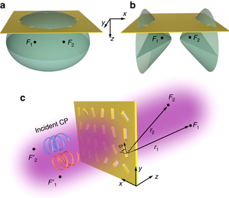
We first consider an ellipsoid and a hyperboloid (Figure 1a and 1b), which are defined by the equations r1+r2=constant and r1−r2=constant, respectively, where r1 and r2 are the distances from the quadric surfaces to their two foci F1 (x1, y1, z1) and F2 (x2, y2, z2), respectively. To investigate the spin optical properties of the two surfaces, we introduce a geometric-phase term σ±ψ and then rewrite the equations as follows:
where k is the wave vector of light, and σ±=±1 corresponds to the helicity (or spin) of the right- (RCP) and left- (LCP) CP light. Assuming that the geometric-phase distribution satisfies the constraint that the phase term within the first bracket kr1+σ±ψ is a constant value (modulo 2π) over the two quadric surfaces, the phase terms within the second brackets will also automatically be constant values. In other words, light with different spin states can simultaneously and constructively interfere at each of the two foci of the ellipsoid, and light with one particular spin state can be accumulated (and constructively interfere) at both foci of the hyperboloid. The simultaneous constructive interference at all the foci is the intrinsic property of these two surfaces, which is also the expected property for an ideal multifocal lens. Figure 1a and 1b, shows the plane of a designed ultrathin metalens intersecting with the ellipsoid and hyperboloid, and results in an elliptical curve and a hyperbolic curve, respectively. We call these metalenses the ellipse-shaped metalens (ESM, Figure 1a) and the hyperbola-shaped metalens (HSM, Figure 1b) because they can focus light at the foci of the quadric surfaces F1 and F2.
Figure 1.
Design of a multifocal metalens with conic shapes. Schematics of (a) an ellipsoid and (b) a hyperboloid with the two foci at points F1 and F2. The intersection of a plane with the ellipsoid (hyperboloid) results in an elliptical (hyperbolic) curve. (c) Schematic of a metalens composed of nanoslits with two foci at F1 and F2 under the illumination of CP light. ϕ is the orientation angle of a nanoslit relative to the x axis. Points F1′ and F2′ are the mirror points of F1 and F2, respectively, with respect to the metalens.
The traditional method for constructing a two-foci metalens is to design two areal patterns with each of the areas presenting one functionality25, 26, 29. However, as mentioned before, such a metalens cannot focus light constructively at both foci; therefore, the background noise is high, and the imaging quality is reduced. As we demonstrate below, our proposed conic-shaped metalenses are able to decrease the background noise and improve the lens imaging performance.
The introduced geometric phase in Equations (1) and (2) can be provided by various elements, such as V-shape, C-shape and long-strip nanostructures. For simplicity, we choose the nanoslit perforating a metallic film as the geometric-phase provider. With the illumination of RCP/LCP light, the transmitted light through a nanoslit carries an additional geometric phase ±2ϕ (ψ=2ϕ) in its cross polarization5, 6, 17, 30, where ϕ is the orientation angle of the nanoslit relative to the x axis, as shown in Figure 1c. The orientation of each nanoslit of the ESM and the HSM can be determined by the constraint equation of kr1+2σ±ϕ=constant (modulo 2π). This condition guarantees that the terms within the second brackets in Equations (1) and (2) are constant values. Because of the subwavelength size of each nanoslit, the transmission through the metalens is expected to be relatively low. As an alternative to metallic nanoslits, high-index dielectric strips18 can be used to enhance the transmission efficiency of the metalens. Because the purpose of this work is to demonstrate the advantages of a conic-shaped metalens, the enhancement of transmission efficiency is beyond of the scope of this paper.
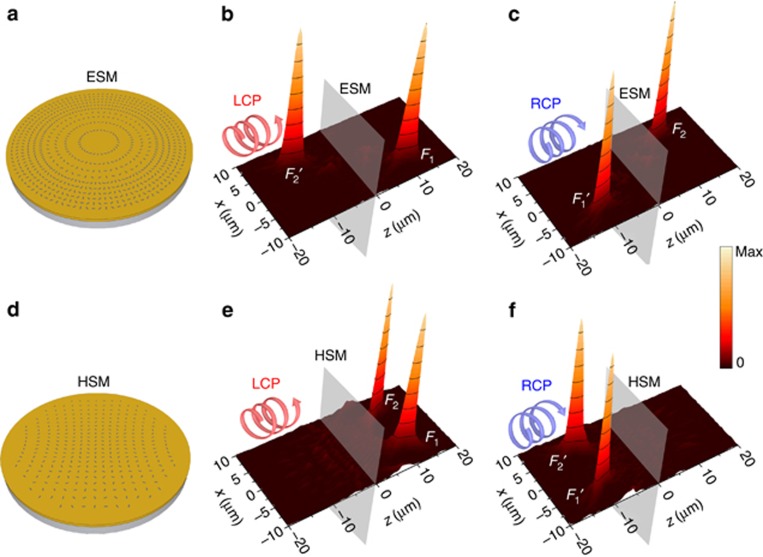
To verify our proposed idea, the geometric phases in the ESM are chosen such that LCP light is focused at F1(x1, y1, z1) (−2ϕ+kr1=constant) and RCP light is automatically focused at F2(x2, y2, z2) (2ϕ+kr2=constant). For the HSM, the LCP light is designed to be focused at point F1 (−2ϕ+kr1=constant), and, at the same time, constructive interference occurs at F2 (−2ϕ+kr2=constant). Figure 2a and 2d, shows the two metalenses with a radius of 10 μm, operating at a wavelength of 785 nm (see Supplementary Fig. S1 for the complete design patterns). The coordinates of the two focal points are x1=−x2=−5 μm, y1=y2=0 μm and z1=z2=10 μm. The size of each nanoslit should be subwavelength and narrow, with the long-axis length much greater than the short-axis length. Each nanoslit has a width of 100 nm and a length of 300 nm.
Figure 2.
Numerical demonstration of the focusing of CP light using the ESM and the HSM. (a) Schematics of the designed ESM and (b, c) simulated electric field intensities at the xz plane (x∈[−10,10] μm, y=0 μm, z∈[−20,20] μm) for (b) LCP and (c) RCP incident light. (d–f) The same as a–c, but for the HSM. The CP light is incident from the left side and is scattered to the right side of the metalens. The distance between the two focal points (F1 and F2) is 10 μm, and the focal length of the metalens is f=10 μm. The metalens is located at the plane z=0 μm.
To confirm our prediction, finite-difference time-domain simulations were performed to calculate the electric field intensities at the xz plane with y=0 μm. The fields at the virtual plane are contributed by the transmitted light and are formed at the positions where the rays would cross if they were projected backward. Details of the calculations of the fields at any positions (including the virtual plane) can be found in the Supplementary Information. Figure 2b and 2c, shows the field intensity distributions of the ESM with LCP (Figure 2b) and RCP (Figure 2c) incident light. As expected, LCP and RCP light are focused at F1 and F2, respectively, as the manifestation of the optical spin Hall effect. Moreover, we also observe a virtual focal point F2′ (mirror point of F2) with LCP incident light and a virtual focal point F1′ (mirror point of F1) with RCP incident light. This observation is made because the ESM also fulfills the following two equations: 2ϕ−kr1=constant and −2ϕ−kr2=constant, which correspond to the virtual focal points F1′ and F2′ with RCP and LCP incident light, respectively. The proposed ESM has dual polarity (positive and negative) with a real and a virtual focus under the illumination of CP light.
For the HSM, Figure 2e shows that there are two focal points F1 and F2 at the real focal plane with the illumination of LCP light. When the polarization is altered to RCP (Figure 2f), two virtual focal points F1′ and F2′ emerge at the virtual focal plane because the HSM also fulfills the two equations: 2ϕ−kr1=constant and 2ϕ−kr2=constant. The polarity of the HSM changes from positive with LCP incident light to negative with RCP incident light. Because linear polarization can be decomposed as a superposition of LCP and RCP, all of the real and virtual focal points can be observed in both the ESM and the HSM with linearly polarized light (Supplementary Fig. S2). The focal properties of the two metalenses can be maintained if each nanoslit is replaced by another shaped element, such as a C-shape (Supplementary Fig. S3). Because the light is focused off-axis of the metalens, the intensity distribution at the focal point is asymmetric. The simulated full-width at half-maximum (FWHM) of the focus along the x axis for both metalenses is ~560 nm, that is, less than the incident wavelength 785 nm. The spot size and the FWHM are strongly dependent on the radius of the metalens and can be reduced by increasing the lens radius (Supplementary Fig. S4).
Results and discussion
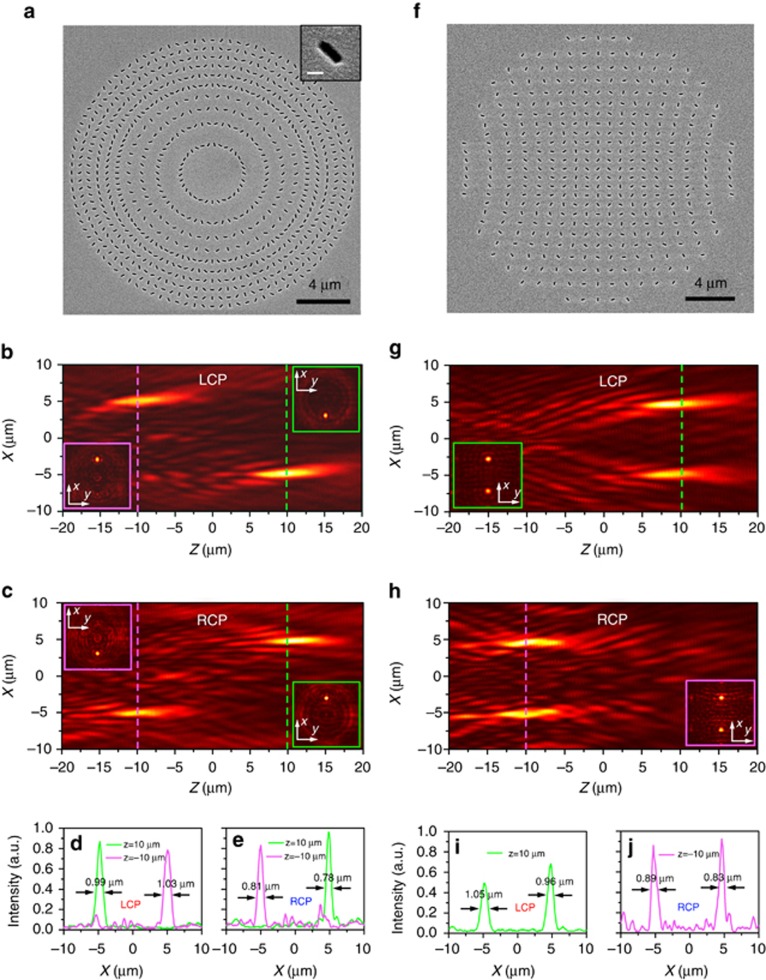
To experimentally demonstrate the focusing performance of the designed metalens, we fabricated two conic-shaped metasurfaces by evaporating an 80-nm thick Au layer onto a glass substrate, followed by focused ion beam milling of the nanoslit pattern into the Au layer (see the Supplementary Information). Because the transmission through a hole decreases exponentially with increasing thickness31, the thickness of the Au layer is chosen such that the level of transmitted light is high enough to be detected. The other parameters of the metalens are exactly the same as those in the finite-difference time-domain simulations. Scanning electron microscopy (SEM) images of these two metalenses are shown in Figure 3a and 3f. Far-field optical microscopy was employed to measure the optical intensity distributions (detection set-up is shown in the Supplementary Information and Supplementary Fig. S5). In the measurement, a motorized actuator was used to accurately adjust the distance between the objective lens and the sample. The optical intensity at the xz plane can be obtained from continuous images of the xy planes at set distances above and below the sample.
Figure 3.
Experimental demonstration of the focusing performance of the ESM and the HSM. (a) SEM images of the ESM. Each nanoslit has a width of 100 nm and a length of 300 nm. The inset shows a magnified SEM figure of a nanoslit (scale bar=200 nm). (b, c) Measured xz plane optical field intensities of the ESM with (b) LCP and (c) RCP incident light. The insets show the xy planes at the real focal plane z=10 μm and at the virtual focal plane z=−10 μm. (d, e) Line plots of the intensities as a function of x at the real and virtual focal planes with (d) LCP and (e) RCP incident light for the ESM. (f–j) The same as in a–e, but for the HSM.
Figure 3b and 3c, shows the measured optical intensities of the ESM with LCP and RCP incident light at a wavelength of 785 nm. Two focal points with one real focus (z=10 μm) and one virtual focus (z=−10 μm) can be clearly observed for both cases but with different focal positions. For the HSM, LCP light can be focused at two real focal points in front of the sample (z=10 μm), and RCP light can be focused at two virtual focal points at the incident side (z=−10 μm), as shown in Figure 3g and 3h.Supplementary Movies 1 and 2 in the Supplementary Information show a gradual evolution of the measured optical intensity at the xy plane with CP light when z ranges from 20 μm to −20 μm for the ESM and the HSM, respectively. The measured FWHM of the focal points along the x-axis range from 0.78 to 1.03 μm for the ESM (Figure 3d and 3e) and range from 0.83 to 1.05 μm for the HSM (Figure 3i and 3j), which are comparable to the incident wavelength 785 nm but are larger than the simulation result of 560 nm. This discrepancy may be due to the inaccuracy of the nanofabrication process and of the measurements.
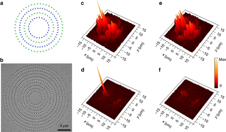
To show the advantages of a multifocal metalens with conic shapes, we use the traditional method to design a metalens with dual foci (Figure 4a), which includes two interleaved zones, with one zone (the green nanoslits) corresponding to the focus F1 under LCP incident light and the other zone (the blue nanoslits) corresponding to the focus F2 under RCP incident light. Figure 4b shows the SEM figure of the traditional metalens, which almost has the same effective areas as those of the ESM (Figure 3a). Figure 4c and 4d, shows the measured field intensities at the real focal plane with LCP incident light for the traditional metalens and for the ESM, respectively. The intensities of the focal peaks of F1 are normalized to the same maxima for fair comparison. A two-dimensional Gaussian function is used to fit the F1 peak as the imaging of the incident plane wave (see the Supplementary Information). The noise is defined as the absolute value of the difference between the total measured field intensities and the Gaussian fitting functions, as shown in Figure 4e and 4f,. The background noise of the traditional metalens is clearly much larger than that of the ESM. The calculated total noise power of the traditional metalens is ~20 times of that of the ESM. Because all the zones in the ESM constructively interfere at its foci, the background noise of the ESM is at approximately the same level as a metalens with a single focus (see Supplementary Information Fig. S6).
Figure 4.
Comparison of the focal performance between the ESM and a traditional metalens. (a) Schematic of the design of the traditional metalens, which is divided into two interleaved zones, with the green nanoslits contributing to one focus and the blue nanoslits contributing to the other focus. (b) SEM image of a traditional metalens. (c, d) The measured field intensities at the real focal plane with LCP incident light for the traditional metalens (c) and for the ESM (d). (e, f) The noise distributions for the traditional metalens (e) and for the ESM (f).
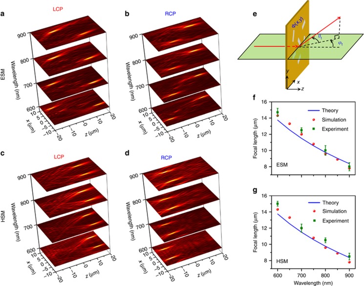
We further demonstrate that our proposed conic-shaped metalenses can function well within a broadband wavelength that ranges from 600 to 900 nm. Figure 5a–5d shows the measured optical intensities of the xz planes for the two metalenses at selected wavelengths of 600, 700, 800 and 900 nm. The focal points can be clearly observed for all cases, which is in good agreement with our simulation results in Supplementary Fig. S7. However, the position of the focus varies with the wavelengths for both metalenses. Figure 5f and 5g, presents the simulated (solid red circle) and measured (solid green square) results, which show that the focal length decreases with increases of the incident light wavelength. This phenomenon is associated with the intrinsic dispersion of the optical lens and can be explained by the generalized Snell’s laws of out-of-plane refraction7, 8. Take the focal point F1 as an example; the phase shift ϕs(x, y) induced by the metalens is
Figure 5.
Broadband focal properties for the ESM and the HSM. (a–d) Measured xz plane (x∈[−10,10] μm, z∈[−20,20] μm) optical intensities of (a, b) the ESM and (c, d) the HSM with LCP and RCP incident light at wavelengths (z axis) of 600, 700, 800 and 900 nm. (e) Schematic of the defection of light incident on a metalens with a phase shift Φ(x,y). The light (red arrow) is normally incident, and the transmission light is defected at angles with ϕt and θt. (f, g) Focal length as a function of wavelength for (f) the ESM and (g) the HSM. The blue line, solid red circle and solid green square show the theoretical predictions, simulated results and experimental results. For each metalens, there are four focal points in total with LCP and RCP incident light. The error bar is defined by the deviation of the focal lengths of the four foci.
The phase gradient  at the metasurface deflects a portion of the normally incident light to transmitted light at an oblique angle that is defined by the two angles ϕt and θt, as shown in Figure 5e. We therefore have7
Substituting Equation (3) into Equation (4), the focal length can be theoretically calculated as cot(ϕt)x1 and is shown as the blue lines in Figure 5f and 5g, which also exhibits a decreasing trend of focal length with increases of the incident wavelength.
Conclusion
In summary, we theoretically and experimentally demonstrated that conic-shaped metasurfaces can be used to design an ideal multifocal lens in the far field. The difference in the focusing performance between the ESM and HSM was also discussed. In comparison with traditional multifocal lenses, our proposed metalenses can constructively focus the incident light at all of the focal points and decrease the background noise of the imaging. We further showed that these two conic-shaped metalenses can possess dual polarity under incident CP light. Moreover, the designed metalenses were found to operate well within a broadband incident wavelength from 600 to 900 nm in the visible range, and the dependence of the focal length on incident wavelength was successfully explained by the generalized Snell’s law. Our work applies the conic concept in the field of optics and enables the miniaturization of multifocal lenses with improved imaging performance.
Acknowledgments
This work is supported by the National Key Research and Development Program of China (Grant No. 2017YFA0206000), National Basic Research Program of China (973 Program, Grant No. 2015CB932403, 2017YFA0205700), the National Science Foundation of China (Grant No. 61422501, 11674012, 11374023, 61176120, 61378059 and 61521004), the Foundation for the Author of the National Excellent Doctoral Dissertation of PR China (Grant No. 201420) and the National Program for Support of Top-notch Young Professionals.
Footnotes
Note: Supplementary Information for this article can be found on the Light: Science & Applications’ website(http://www.nature.com/lsa).
The authors declare no conflict of interest.
Supplementary Material
References
- Shalaev VM. Optical negative-index metamaterials. Nat Photonics 2007; 1: 41–48. [Google Scholar]
- Smith DR, Pendry JB, Wiltshire MCK. Metamaterials and negative refractive index. Science 2004; 305: 788–792. [DOI] [PubMed] [Google Scholar]
- Liu R, Ji C, Mock JJ, Chin JY, Cui TJ et al. Broadband ground-plane cloak. Science 2009; 323: 366–369. [DOI] [PubMed] [Google Scholar]
- Schurig D, Mock JJ, Justice BJ, Cummer SA, Pendry JB et al. Metamaterial electromagnetic cloak at microwave frequencies. Science 2006; 314: 977–980. [DOI] [PubMed] [Google Scholar]
- Huang LL, Chen XZ, Mühlenbernd H, Li GX, Bai BF et al. Dispersionless phase discontinuities for controlling light propagation. Nano Lett 2012; 12: 5750–5755. [DOI] [PubMed] [Google Scholar]
- Li GX, Kang M, Chen SM, Zhang S, Pun EYB et al. Spin-enabled plasmonic metasurfaces for manipulating orbital angular momentum of light. Nano Lett 2013; 13: 4148–4151. [DOI] [PubMed] [Google Scholar]
- Aieta F, Genevet P, Yu NF, Kats MA, Gaburro Z et al. Out-of-plane reflection and refraction of light by anisotropic optical antenna metasurfaces with phase discontinuities. Nano Lett 2012; 12: 1702–1706. [DOI] [PubMed] [Google Scholar]
- Yu NF, Genevet P, Kats MA, Aieta F, Tetienne JP et al. Light propagation with phase discontinuities: generalized laws of reflection and refraction. Science 2011; 334: 333–337. [DOI] [PubMed] [Google Scholar]
- Bao YJ, Zu S, Zhang YF, Fang ZY. Active control of graphene-based unidirectional surface plasmon launcher. ACS Photonics 2015; 2: 1135–1140. [Google Scholar]
- Liu LX, Zhang XQ, Kenney M, Su XQ, Xu NN et al. Broadband metasurfaces with simultaneous control of phase and amplitude. Adv Mater 2014; 26: 5031–5036. [DOI] [PubMed] [Google Scholar]
- Li ZY, Palacios E, Butun S, Aydin K. Visible-frequency metasurfaces for broadband anomalous reflection and high-efficiency spectrum splitting. Nano Lett 2015; 15: 1615–1621. [DOI] [PubMed] [Google Scholar]
- Yu NF, Capasso F. Flat optics with designer metasurfaces. Nat Mater 2014; 13: 139–150. [DOI] [PubMed] [Google Scholar]
- Shitrit N, Yulevich I, Maguid E, Ozeri D, Veksler D et al. Spin-optical metamaterial route to spin-controlled photonics. Science 2013; 340: 724–726. [DOI] [PubMed] [Google Scholar]
- Tymchenko M, Gomez-Diaz JS, Lee J, Nookala N, Belkin MA et al. Gradient nonlinear pancharatnam-berry metasurfaces. Phys Rev Lett 2015; 115: 207403. [DOI] [PubMed] [Google Scholar]
- Cui TJ, Qi MQ, Wan X, Zhao J, Cheng Q. Coding metamaterials, digital metamaterials and programmable metamaterials. Light Sci Appl 2014; 3: e218. [Google Scholar]
- Aieta F, Genevet P, Kats MA, Yu NF, Blanchard R et al. Aberration-free ultrathin flat lenses and axicons at telecom wavelengths based on plasmonic metasurfaces. Nano Lett 2012; 12: 4932–4936. [DOI] [PubMed] [Google Scholar]
- Chen XZ, Huang LL, Muhlenbernd H, Li GX, Bai BF et al. Dual-polarity plasmonic metalens for visible light. Nat Commun 2012; 3: 1198. [DOI] [PMC free article] [PubMed] [Google Scholar]
- Khorasaninejad M, Chen WT, Devlin RC, Oh J, Zhu AY et al. Metalenses at visible wavelengths: diffraction-limited focusing and subwavelength resolution imaging. Science 2016; 352: 1190–1194. [DOI] [PubMed] [Google Scholar]
- Ding XM, Monticone F, Zhang K, Zhang L, Gao DL et al. Ultrathin pancharatnam-berry metasurface with maximal cross-polarization efficiency. Adv Mater 2015; 27: 1195–1200. [DOI] [PubMed] [Google Scholar]
- Khorasaninejad M, Chen WT, Oh J, Capasso F. Super-dispersive off-axis meta-lenses for compact high resolution spectroscopy. Nano Lett 2016; 16: 3732–3737. [DOI] [PubMed] [Google Scholar]
- Aieta F, Kats MA, Genevet P, Capasso F. Multiwavelength achromatic metasurfaces by dispersive phase compensation. Science 2015; 347: 1342–1345. [DOI] [PubMed] [Google Scholar]
- Pors A, Nielsen MG, Eriksen RL, Bozhevolnyi SI. Broadband focusing flat mirrors based on plasmonic gradient metasurfaces. Nano Lett 2013; 13: 829–834. [DOI] [PubMed] [Google Scholar]
- Jia J, Zhou CH, Liu LR. Superresolution technology for reduction of the far-field diffraction spot size in the laser free-space communication system. Opt Commun 2003; 228: 271–278. [Google Scholar]
- de Gracia P, Dorronsoro C, Marcos S. Multiple zone multifocal phase designs. Opt Lett 2013; 38: 3526–3529. [DOI] [PubMed] [Google Scholar]
- Chen XZ, Chen M, Mehmood MQ, Wen DD, Yue FY et al. Longitudinal multifoci metalens for circularly polarized light. Adv Opt Mater 2015; 3: 1201–1206. [Google Scholar]
- Wang W, Guo ZY, Zhou KY, Sun YX, Shen F et al. Polarization-independent longitudinal multi-focusing metalens. Opt Express 2015; 23: 29855–29866. [DOI] [PubMed] [Google Scholar]
- Mehmood MQ, Mei ST, Hussain S, Huang K, Siew SY et al. Visible-frequency metasurface for structuring and spatially multiplexing optical vortices. Adv Mater 2016; 28: 2533–2539. [DOI] [PubMed] [Google Scholar]
- Bao YJ, Zu S, Liu W, Zhou L, Zhu X et al. Revealing the spin optics in conic-shaped metasurfaces. Phys Rev B 2017; 95: 081406. [Google Scholar]
- Khorasaninejad M, Chen WT, Zhu AY, Oh J, Devlin RC et al. Multispectral chiral imaging with a metalens. Nano Lett 2016; 16: 4595–4600. [DOI] [PubMed] [Google Scholar]
- Huang LL, Chen XZ, Bai BF, Tan QF, Jin GF et al. Helicity dependent directional surface plasmon polariton excitation using a metasurface with interfacial phase discontinuity. Light Sci Appl 2013; 2: e70. [Google Scholar]
- Degiron A, Lezec HJ, Barnes WL, Ebbesen TW. Effects of hole depth on enhanced light transmission through subwavelength hole arrays. Appl Phys Lett 2002; 81: 4327–4329. [Google Scholar]
Associated Data
This section collects any data citations, data availability statements, or supplementary materials included in this article.


