Abstract
Increasing the system capacity and spectral efficiency (SE) per unit bandwidth is one of the ultimate goals for data network designers, especially when using technologies compatible with current embedded fiber infrastructures. Among these, the polarization-division-multiplexing (PDM) scheme, which supports two independent data channels on a single wavelength with orthogonal polarization states, has become a standard one in most state-of-art telecommunication systems. Currently, however, only two polarization states (that is, PDM) can be used, setting a barrier for further SE improvement. Assisted by coherent detection and digital signal processing, we propose and experimentally demonstrate a scheme for pseudo-PDM of four states (PPDM-4) by manipulation of four linearly polarized data channels with the same wavelength. Without any modification of the fiber link, we successfully transmit a 100-Gb s−1 PPDM-4 differential-phase-shift-keying signal over a 150-km single-mode fiber link. Such a method is expected to open new possibilities to fully explore the use of polarization freedom for capacity and SE improvement over existing fiber systems.
Keywords: coherent detection, optical communication, pseudo-polarization-division multiplexing, spectral efficiency
Introduction
Polarization of light, as one of the most fundamental physical quantities in classical and quantum mechanics, has a pivotal role in numerous applications, such as high-capacity transmission1, 2, photon ionization3, sub-wavelength localization4, waveform generation5, 6 and coherent multidimensional spectroscopy7. Among these, high-capacity transmission techniques have attracted successively more attention as a result of ever-increasing data traffic during the past few years. As an additional degree of freedom, manipulation of the state of polarization (SOP) of light, as well as the amplitude and phase could determine the time evolution of the signal and improve both the system capacity and the spectral efficiency (SE). One of the most popular polarization manipulation technologies is the polarization-division-multiplexing (PDM) strategy8, which combines two linear and orthogonal SOPs over a single wavelength. Because it is uncoupled to other optimization approaches, PDM can be applied to almost any system including wavelength-division multiplexing9, 10, optical time-division multiplexing11, mode-division multiplexing12 and space-division multiplexing (SDM)13 systems. Beyond linear polarization manipulation, there has been an increasing interest in signal multiplexing with spatially inhomogeneous SOPs such as vortex beams14, 15, 16 and cylindrical vector beams17, 18, 19. On the basis of such unconventional SOPs of light, orbital-angular momentum (OAM) multiplexing has been proposed in both free-space and fiber-based optical communication systems20, 21, 22. The advantages of both SDM and OAM are still under intensive investigation, and the deployment of such schemes requires significant modification or even rebuilding of current fiber networks23. Therefore, improving the system capacity based on the manipulation of linear polarization is still of great interest and would be much more efficient if the maturity of polarization management and high compatibility with current systems were ensured.
Higher-order amplitude modulation such as pulse amplitude-modulated four-level (PAM4) and higher-order phase modulation such as quadrature phase shift keying (QPSK) have been widely applied to short-reach communication and long-haul transmission, respectively. However, modulation of polarization, as an independent degree of freedom, is still limited to orthogonal SOPs in PDM systems. It would be highly desirable if the orthogonality of polarization could be broken24, 25 to enable the signal (that is, both intensity modulation and phase modulation) to accommodate more polarization states at a single wavelength, similar to higher-level amplitude and phase. Transmission multiplexing with more than two conventional SOPs was reported as long ago as 1986, when it was implemented in free space26. Recently, focus has turned to the construction of novel communication systems through additional polarization manipulation27, 28. On the basis of fundamental principles underlying these approaches, only on-off-keying (OOK) signal transmissions have been achieved either theoretically or experimentally. Among these28, describes the first experimental attempt of quad-polarization transmission, in which four SOPs are carried by four individual wavelengths (unlike conventional PDM approaches), and the transmission distance is limited to only 2 km. Therefore, the feasibility of improving SE (that is, quadrupling or improving by even larger factors), using advanced modulation formats (for example, phase shift keying), and transmitting over longer distance by polarization manipulation is still questionable.
In this paper, we propose and experimentally demonstrate a pseudo-PDM of four states (PPDM-4) system over standard single-mode fiber (SMF) to explore the use of polarization freedom. In contrast to the four-dimensional modulation format29, the four input streams of the proposed system are fully independent of each other. Assisted by polarization manipulation, coherent detection and digital signal processing (DSP), four differential-phase-shift-keying (DPSK) data streams with the same wavelength (that is, PPDM-4 DPSK) are transmitted using four linear SOPs. The neighboring angles of the multiplexed signal are 0°, 30°, 90° and 120°. Two coherent detectors are used at the receiver side whose polarization principal axes are aligned to the SOPs of four input signals. The 100-Gb s−1 PPDM-4 DPSK signals are effectively transmitted over a 150-km SMF link with less than an 8-dB power penalty. Furthermore, the potential of the PPDM-4 DPSK system is shown to be comparable to PDM-QPSK systems under the same capacity and the same SE. As the first attempt to transmit more than two polarization states over a single-wavelength and standard fiber links, such demonstration may open an era for network designers to further use polarization freedom for ultra-high SE and capacity fiber communication systems after further optimization (for example, the incorporation of demultiplexing schemes and processing algorithms).
Materials and methods
Polarization recognition and manipulation based on Stokes vector
One of the most popular methods of polarization demultiplexing for PDM signals, especially for complex modulated signals, is to utilize the Stokes vector in the Poincaré sphere. Typically, after chromatic dispersion compensation and timing recovery, the Stokes space representation of a signal is obtained by computing the Stokes parameters of linearly polarized received signals according to Equation (1)30.
 |
where ax and ay are the amplitudes of two received signals from the coherent receiver and Δθ is the phase difference between these two signals. The first component of the Stokes vector s0 is the total power, whereas the remaining components, [s1, s2, s3]T, represent the SOP of the received signal. The vector [s1, s2, s3]T allows for visualization of the SOP on the Poincaré sphere after normalization using the maximum of the vector s0. It is important to note that the signal described by the Stokes vector is independent of linewidth, frequency offset, and pulse shaping as Equation (1) contains only the amplitudes of the two received signals and their relative phase difference.
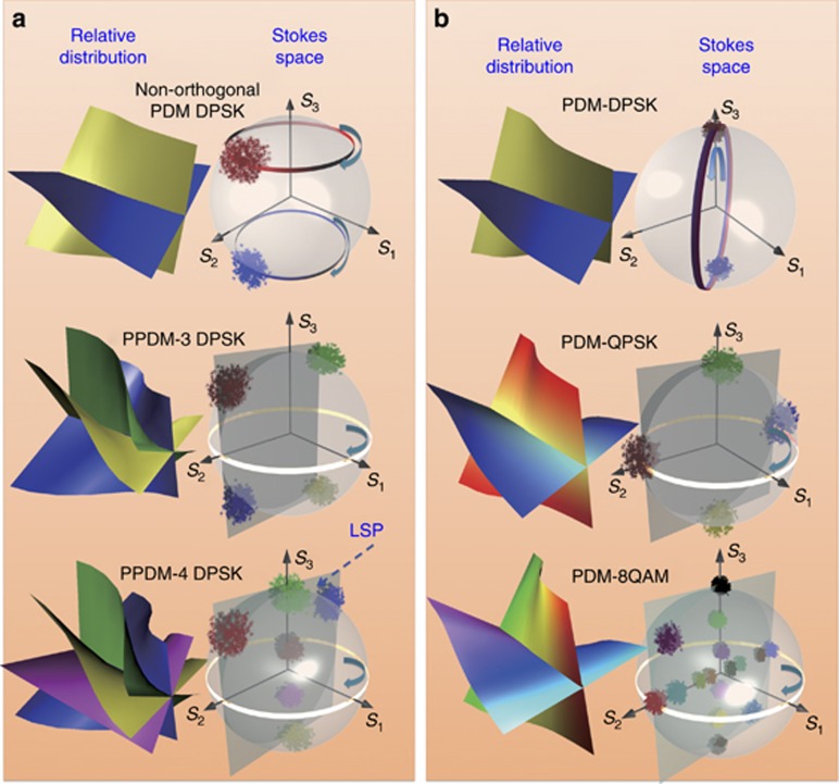
On the basis of Equation (1), illustrations of unconventional and conventional polarization-multiplexed schemes in the relative distribution and the Stokes space are shown in Figure 1. The left column shows the DPSK signals multiplexed with non-orthogonal polarizations, three polarizations and four polarizations (Figure 1a). For comparison, we also illustrate the conventional PDM strategy for three different standard modulation formats: DPSK; QPSK; and 8-quadrature amplitude modulation (QAM)31 (Figure 1b). As can be observed from the relative distribution of the signal, in which the phase evolution is denoted by color shading, great differences exist between unconventional and conventional polarization multiplexing, especially for the PPDM-4 signal, whose four polarizations are clearly tangled. However, in the Stokes space, the distribution and trajectory (circles in Figure 1) of the Stokes vector for both multiplexing strategies are similar. Therefore, similar to the polarization demultiplexing of PDM-QPSK and PDM-8QAM, PPDM-4 DPSK could be demultiplexed as well based on Stokes analysis. It is noted that the images of the Stokes space of the PPDM-4 DPSK signal reveal several interesting characteristics. (i) Six symbols (or clusters) are presented when the signal maps to the Stokes space, and all points are in a plane; (ii) the transitions that are linear in the phase plane occupy more complicated trajectories in the Stokes space; and (iii) clusters rotate arbitrarily, maintaining their relative positions.
Figure 1.
Illustration of unconventional and conventional polarization-multiplexed schemes in relative distribution and the Stokes space. (a) DPSK signal multiplexing with two non-orthogonal polarizations, three polarizations and four polarizations. (b) Conventional polarization-multiplexed schemes of three different standard modulation formats, including PDM-DPSK, PDM-QPSK and PDM-8QAM.
According to the characteristic of PPDM-4 DPSK in the Stokes space, a clustering algorithm for classifying data sets into separate groups is used to recognize the positions of the clusters’ centroids (uk) by minimizing the parameter defined by Equation (2).
where K, N and J are the number of clusters, number of sampling points and cost function, respectively. Subsequently, the plane of these Stokes vectors and its normal can be defined by using the least-square algorithm, and this plane as shown in Figure 1 can be termed the least squares plane (LSP).
Assuming that the normal of the standard LSP is aligned to the S1 direction in the Poincaré sphere, whose value is [1,0,0]T, the arbitrary LSP with the normal of n ([n1,n2,n3]T) can be rotated to be aligned to the standard LSP by using a matrix, which is given by30
where  and Δϕ=arctan (n2, n3). The function arctan (x, y) accounts for the signs of x and y. By using Equation (3), the polarization states of light can be manipulated arbitrarily.
Multiplexing and demultiplexing of PPDM-4 DPSK signal
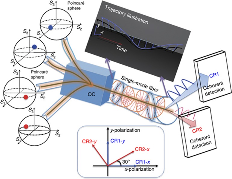
The key components of the PPDM-4 DPSK system are the multiplexing and demultiplexing schemes, whose conceptual illustration is shown in Figure 2. Four independent DPSK signals with four different polarizations are multiplexed using four polarization controllers and an optical coupler. Assuming that the SOP of the first channel is 0°, the SOPs of the others are 30°, 90° and 120°, respectively. The multiplexed signal is subsequently transmitted over SMF with varying polarization, whose typical trajectory is illustrated in the inset of Figure 2.
Figure 2.
Conceptual illustration of PPDM-4 DPSK system for long-haul transmission. Insets illustrate the typical trajectory of PPDM signal transmission in the fiber and the relationship of four principal axes of two coherent receivers. OC, optical coupler.
At the receiver side, the PPDM-4 DPSK signal is first split into two streams (that is, E1 and E2) by an optical coupler. Subsequently, two coherent receivers (CR1 and CR2) are used to detect the signal and extract the Stokes vector S. However, in practical applications, the extracted Stokes vector varies randomly over time. Therefore, polarization tracking (as well as DPSK signal demodulation) has the key role in the demultiplexing algorithm.
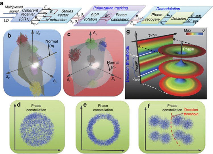
Taking CR1 as an example, four received I and Q signals (that is, E1xI, E1xQ, E1yI and E1yQ) are sent to the real-time oscilloscope to recover the two complex signals E1x and E1y; the DSP algorithm for polarization demultiplexing is shown in Figure 3a. First, the transmitter and CR1 are assumed to be in the same coordinate system; therefore, one polarization principal axis of CR1 is aligned to the S1 direction on the Poincaré sphere, where S1 represents the linear horizontal polarization state. During demultiplexing, one of four polarization tributaries (that is, 0° polarization) should always be aligned in the S1 direction. However, in practical systems, misalignment between the received PPDM-4 DPSK signal and the principal axis of CR1 would result in arbitrary rotation of the clusters because of the random variation of the polarization as shown in Figure 3b. In this case, the phase of the detected signal appears chaotic, as illustrated in Figure 3d. Subsequently, the SOP of the received signal is rotated by using Equation (3), resulting in the vector normal to the LSP being aligned in the S1 direction (Figure 3c). As a result, the final data of CR1 after polarization manipulation are expressed as follows:
Figure 3.
Algorithm of PPDM-4 DPSK signal demultiplexing; (a) illustrates main modules of signal demultiplexing algorithm. (b, c) The theoretical SOP of multiplexed signal before and after polarization tracking, respectively. The polarization principal axis of CR1 is aligned to S1 direction. (d, e) The phase constellation before and after polarization tracking. (f) The phase constellation after linewidth compensation. (g) The phase density diagram for determining the decision thresholds.
The theoretical phase constellation of multiplexed signal after polarization manipulation is shown in Figure 3e. Clearly, the signal, whose phase exhibits serious fluctuations because of the linewidth of the laser, still cannot be separated. Therefore, phase recovery and decision are required in the demodulation block. In the conventional PDM-QPSK system, the Viterbi–Viterbi method is widely used to estimate and compensate the carrier phase, which is also applied to the PPDM-4 DPSK system. After the linewidth compensation, the phase constellation is split into eight points as shown in Figure 3f; four of them are very close. This phenomenon occurs because a part of the neighboring channels (that is, 30° and 120° polarization) are coupled into the 0°/120° polarization channel when the signal is demultiplexed. In contrast to the conventional PSK signal, the symbol decision of PPDM-4 DPSK is challenging to perform in phase space as the phase constellation diagram is not orthonormalized. Therefore, a novel visual illustration termed the phase density diagram is provided to determine the decision thresholds as shown in Figure 3g, where color denotes the density of the signal phases. Typically, the phase density of PPDM-4 DPSK is divided into three levels at any time point. Between these levels, two decision thresholds (that is, uthh1 and uthh2) for the E1x tributary that correspond to the low-density regions can be determined. The two-dimensional diagram of Figure 3g shows the decision thresholds more clearly according to the values of the blue points. Finally, the 0° polarization tributary (or 90° polarization tributary) is determined to be at a low level when uthh2≤uh≤uthh1 (or uthv2≤uv≤uthv1), where uh and uv are the two tributaries after phase recovery. The parameters uthhi and uthvi (i=1 and 2) are decision thresholds for 0° and 90° polarization, respectively. Otherwise, they are at a high level. For the other two channels (that is, 30° and 120° polarization), the demodulation algorithm is the same as in the previous process.
The SOP angle difference between the principle axes of the two CRs is a constant (that is, 30°) according to the inset of Figure 2. Therefore, one of the CRs (namely, CR2) might be removed when the received signal after Stokes vector extraction and SOP rotation (Figure 3a) is divided into two streams, one of which is then rotated by 30° in the Jones space according to [cos(30°) sin(30°); −sin(30°) cos(30°)] × [E1h E1v]T. In this case, the additional 30° SOP rotation can be equal to the CR2 alignment, and the two coherent receivers can be reduced to one. However, by using this method, a performance difference between the 0°/90° polarization channel and the 30°/120° polarization channel appears.
Experimental configuration
The experimental configuration of the 4 × 25 Gb s−1 PPDM-4 DPSK optical communication system over 150-km SMF transmission is shown in Figure 4. At the transmitter, the light from an external cavity laser at 1550 nm is first divided into four streams and then modulated by four phase modulators with a 215−1 pseudorandom bit sequence. Subsequently, the signals are polarization multiplexed to generate a PPDM-4 DPSK signal using four polarization controllers and a 4 × 1 optical coupler. The multiplexed signal is aligned to the chosen SOPs, including 0°, 30°, 90° and 120°. Here four variable optical attenuators are applied in four branches to balance the power among these. No symbol synchronization is required here. Subsequently, the PPDM-4 DPSK signal launches into a 150-km SMF, whose loss is compensated by an erbium-doped fiber amplifier.
Figure 4.
Experimental configuration for PPDM-4 DPSK system. ECL, external cavity laser; LO, local oscillator; PC, polarization controller; PM, phase modulator; VOA, variable optical attenuator.
At the receiver side, the multiplexed signal is split into two streams by an optical coupler and then detected by two coherent receivers with a local oscillator. After photodetection, the electrical signals are digitized and sent to the real-time oscilloscope with a bandwidth of 36 GHz to perform DSP functionalities, including resampling, Stokes vector extraction, polarization rotation, phase calculation, phase recovery, decision and decoding.
Results and discussion
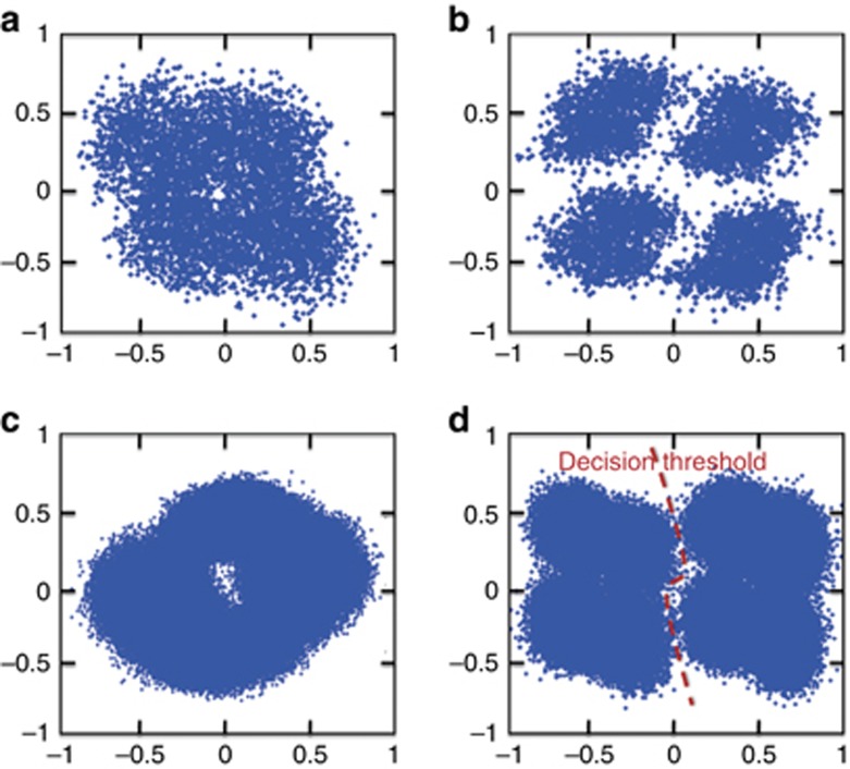
Taking one output of CR1 (that is, E1x) as an example, the constellation diagrams of this channel before and after polarization rotation are shown in Figure 5a and 5b, where the power before CR1 is −19.36 dBm (−22.36 dBm for each tributary). In this case, 6000 b are processed to calculate the phase constellation, which is able to avoid the phase noise of the optical carrier because of the slow variation of the linewidth. As can be observed from Figure 5a and 5b, the constellation becomes clearer after polarization rotation (Equations (3) and (4)). When the SOP of the 0° polarization tributary is aligned to the one polarization principal of CR1 (that is, the S1 direction), the compensation performance is at the optimum level. Figure 5c and 5d, shows the constellation diagrams before and after carrier phase recovery. The linewidth of the used laser causes the phase information to become chaotic. However, by applying the phase recovery, the constellation, which is split into two parts, becomes clearer. Carrier phase recovery can thus be successfully realized in a PPDM-4 DPSK coherent system. It is noted that eight phase points are observed in Figure 5d because of the mapping from the neighboring tributaries, including 30° polarization and 120° polarization. The decision threshold is illustrated in Figure 5d as well. As mentioned above, this decision threshold is challenging to determine as the clusters of phase are not orthonormalized.
Figure 5.
Measured phase constellation diagrams; (a, b) the phase constellations before and after polarization tracking, respectively. (c, d) The phase constellations before and after phase recovery, respectively.
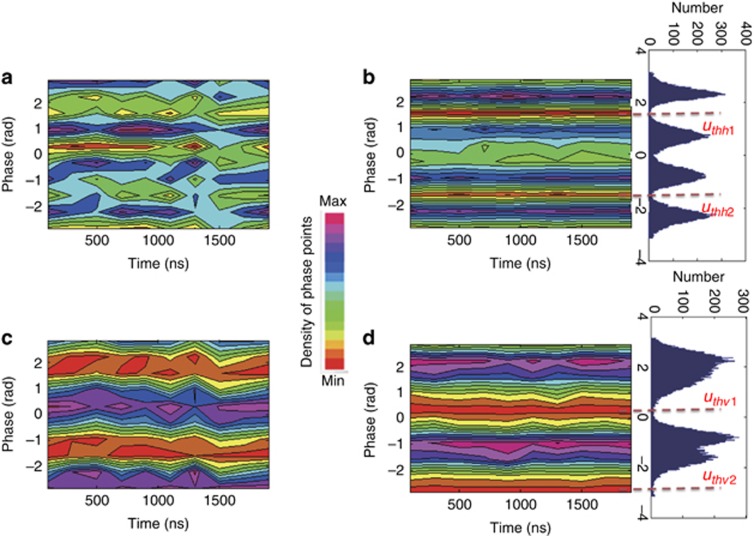
Figure 6 shows the phase density diagrams before and after phase recovery for 0° and 90° polarization, respectively. The color denotes the density of the phase point. As can be observed from Figure 6a and 6c, large crosstalk of the phase can be observed as the color distribution exhibits considerable variation. As a result of the phase recovery, the layers of phase density become clearer, and the decision thresholds can be determined according to the values of the red lines. The corresponding histogram of phase density is presented as well according to Figure 6b and 6d, and illustrates the thresholds more clearly.
Figure 6.
Experimental observation of phase density diagrams; (a, b) the phase density of 0° polarization before and after phase recovery; (c, d) the phase density of 90° polarization before and after phase recovery.
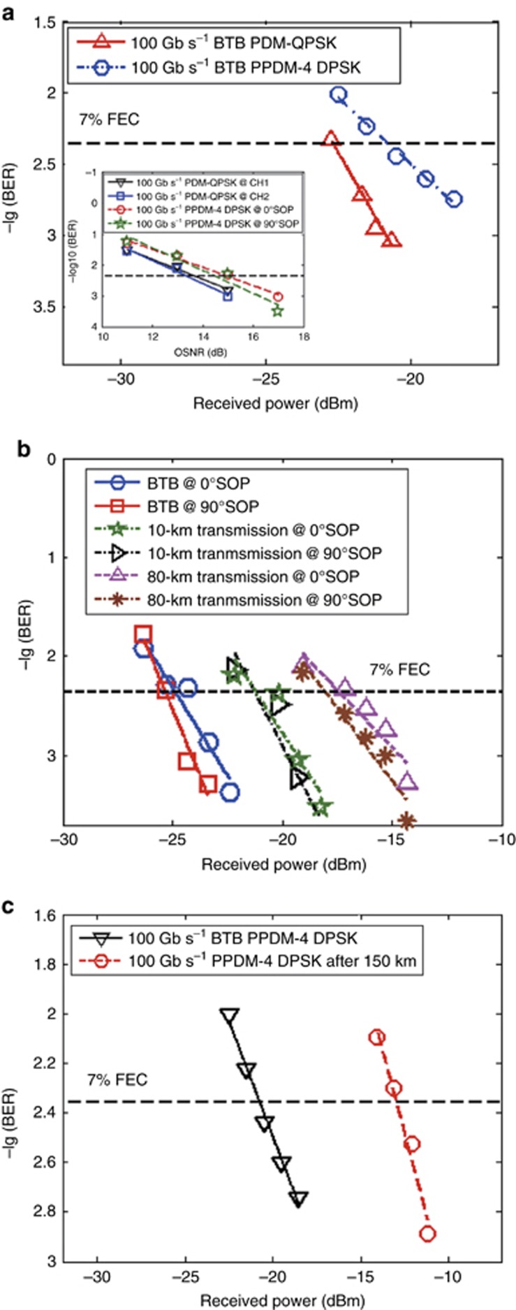
To investigate the practical usage of the PPDM-4 DPSK system, the back-to-back (BTB) bit-error-rate performance of a 4 × 25-Gb s−1 PPDM-4 DPSK system is compared with that of a 100 Gb s−1 PDM-QPSK signal under the same SE as shown in Figure 7a. The hard-decision 7% overhead forward error-correcting (FEC) threshold is depicted for reference. It can be observed that the power penalty is ~2 dB at the 7% FEC threshold. This finding indicates that the proposed scheme can be used as an alternative to PDM-QPSK in a flexible-rate coherent system, which demonstrates the potential of using the freedom of polarization for future optical networks to further increase the system capacity and SE without changing current devices or system structures.
Figure 7.
Measured bit-error-rate performances; (a) the performance comparison between PPDM-4 DPSK system and PDM-QPSK system under the same SE and the same bit rate (100 Gb s−1). Inset illustrates the simulation results; (b) the BTB, 10 and 80-km transmission bit-error-rate (BER) performances for 40 Gb s−1 DPSK signal; (c) the BTB and 150-km transmission performances for 100-Gb s−1 PPDM-4 DPSK signal.
To further evaluate the system performance, the bit error rate under different transmission rates and different transmission lengths are also compared as shown in Figure 7b. Here only tributaries of 0° and 90° polarization are presented as the performance of the other two channels (that is, 30° and 120° polarization) is similar to these two tributaries. The hard-decision 7% overhead FEC threshold is depicted for reference as well. When the transmission rate decreases to 40 Gb s−1, the BTB receiver sensitivities of 0° and 90° polarization are −25.3 and −24.9 dB, respectively. Subsequently, when the PPDM-4 DPSK signal is fed into the 10 and 80 km SMF, the receiver sensitivities at 7% FEC are −21.24, −21.19, −18.04 and −17.41 dB for 0° and 90° polarization. Finally, the BTB and transmission performances of a 100-Gb s−1 PPDM-4 DPSK signal is also investigated as shown in Figure 7c. A transmission distance of up to 150-km is realized with a power penalty of 8 dB.
Although a power penalty of ~2 dB appears compared with the PDM-QPSK system at the present stage, we still anticipate that the performance of the proposed system could approach that of the PDM-QPSK system (that is, a power penalty of <1 dB, as shown in the inset of Figure 7a), if more effective phase recovery and polarization tracking algorithms are used. Such optimization will be conducted in the near future.
In addition, the proposed demultiplexing scheme can be extended to the system multiplexed with more than four polarizations. Taking the PPDM-5 DPSK system (that is, 0°, 30°, 45°, 90° and 120°) as an example, the multiplexed signals can be recovered when the decision thresholds are determined based on the phase density property. However, two issues should be addressed: (i) polarization alignment is realized by adjusting polarization controller before the coherent receiver instead of rotating the Stokes vector based on Equations (3) and (4) as eight clusters presented in the Stokes space are not in one plane; (ii) the demultiplexing performance of the 45° polarization channel is worse than other channels because more crosstalk noise are coupled into this channel (the insertion loss is not the main reason as it can be compensated easily using commercial erbium-doped fiber amplifier). Therefore, the system performance is expected to degrade as the number of multiplexed polarizations increases. In conclusion, this manuscript provides a first-step investigation for exploring the feasibility of the PPDM-4 system. We note that certain challenges need to be further investigated, such as real-time processing and more efficient linewidth compensation and polarization tracking.
Conclusions
With the aiming of fully exploring the polarization freedom for high-performance optical fiber communication systems to significantly enhance capacity and SE, we have proposed a novel configuration of signal multiplexing with four linear polarization states and investigated its transmission performance over SMF. Assisted by coherent detection and DSP, the demultiplexing schemes for a PPDM-4 DPSK signal were presented. Compared with the PDM-QPSK system under the same SE, the power penalty of the proposed system is ~2 dB for 7% FEC. In addition, a 100-Gb s−1 PPDM-4 DPSK signal is successfully transmitted over 150-km SMF with a power penalty of 8 dB. It is expected that the performance will improve after further optimization of related algorithms.
Acknowledgments
This research is supported by the Natural Science Foundation of China (Nos. 61335005, 61325023, 61275068 and 61401378) and the National Basic Research Program of China (2012CB315704). We are especially indebted to P Winzer from Bell Labs for providing many suggestions that greatly improved the manuscript.
Footnotes
The authors declare no conflict of interest.
References
- Liu X, Chraplyvy AR, Winzer PJ, Tkach RW, Chandrasekhar S. Phase-conjugated twin waves for communication beyond the Kerr nonlinearity limit. Nat Photon 2013; 7: 560–568. [Google Scholar]
- Zhang JW, Yu JJ, Chi N. Transmission and full-band coherent detection of polarization-multiplexed all-optical Nyquist signals generated by Sinc-shaped Nyquist pulses. Sci Rep 2015; 5: 13649. [DOI] [PMC free article] [PubMed] [Google Scholar]
- Brixner T, Krampert G, Pfeifer T, Selle R, Gerber G et al. Quantum control by ultrafast polarization shaping. Phys Rev Lett 2004; 92: 208301. [DOI] [PubMed] [Google Scholar]
- Aeschlimann M, Bauer M, Bayer D, Brixner T, de Abajo FJG et al. Adaptive subwavelength control of nano-optical fields. Nature 2007; 446: 301–304. [DOI] [PubMed] [Google Scholar]
- Sato M, Higuchi T, Kanda N, Konishi K, Yoshioka K et al. Terahertz polarization pulse shaping with arbitrary field control. Nat Photon 2013; 7: 724–731. [Google Scholar]
- Colas D, Dominici L, Donati S, Pervishko AA, Liew TCH et al. Polarization shaping of Poincaré beams by polariton oscillations. Light Sci Appl 2015; 4: e350. [Google Scholar]
- Brixner T, Stenger J, Vaswani HM, Cho M, Blankenship RE et al. Two-dimensional spectroscopy of electronic couplings in photosynthesis. Nature 2005; 434: 625–628. [DOI] [PubMed] [Google Scholar]
- Evangelides SG Jr, Mollenauer LF, Gordon JP, Bergano NS. Polarization multiplexing with solitons. J Lightw Technol 1992; 10: 28–35. [Google Scholar]
- Maher R, Xu TH, Galdino L, Sato M, Alvarado A et al. Spectrally shaped DP-16QAM super-channel transmission with multi-channel digital back-propagation. Sci Rep 2015; 5: 8214. [DOI] [PMC free article] [PubMed] [Google Scholar]
- Takara H, Mizuno T, Kawakami H, Miyamoto Y, Masuda H et al. Proceedings of the 2014 European Conference on Optical Communication; 21–25 September 2014. IEEE: Cannes, France; 2014. [Google Scholar]
- Nakazawa M, Yamamoto T, Tamura KR. 1.28 Tbit/s-70 km OTDM transmission using third- and fourth-order simultaneous dispersion compensation with a phase modulator. Electron Lett 2000; 36: 2027–2029. [Google Scholar]
- Huang H, Milione G, Lavery MPJ, Xie GD, Ren YX et al. Mode division multiplexing using an orbital angular momentum mode sorter and MIMO-DSP over a graded-index few-mode optical fibre. Sci Rep 2015; 5: 14931. [DOI] [PMC free article] [PubMed] [Google Scholar]
- Richardson DJ, Fini JM, Nelson LE. Space-division multiplexing in optical fibres. Nat Photon 2013; 7: 354–362. [Google Scholar]
- Cai XL, Wang JW, Strain MJ, Morris BJ, Zhu JB et al. Integrated compact optical vortex beam emitters. Science 2012; 338: 363–366. [DOI] [PubMed] [Google Scholar]
- Hadžievski L, Maluckov A, Rubenchik AM, Turitsyn S. Stable optical vortices in nonlinear multicore fibers. Light Sci Appl 2015; 4: e314, doi:10.1038/lsa.2015.87. [Google Scholar]
- Williams MD, Coles MM, Saadi K, Bradshaw DS, Andrews DL. Optical vortex generation from molecular chromophore arrays. Phys Rev Lett 2013; 111: 153603. [DOI] [PubMed] [Google Scholar]
- Youngworth KS, Brown TG. Focusing of high numerical aperture cylindrical-vector beams. Opt Express 2000; 7: 77–87. [DOI] [PubMed] [Google Scholar]
- Zhan QW. Cylindrical vector beams: from mathematical concepts to applications. Adv Opt Photon 2009; 1: 1–57. [Google Scholar]
- Moh KJ, Yuan XC, Bu J, Low DKY, Burge RE. Direct noninterference cylindrical vector beam generation applied in the femtosecond regime. Appl Phys Lett 2006; 89: 251114. [Google Scholar]
- Bozinovic N, Yue Y, Ren YX, Tur M, Kristensen P et al. Terabit-scale orbital angular momentum mode division multiplexing in fibers. Science 2013; 340: 1545–1548. [DOI] [PubMed] [Google Scholar]
- Wang J, Yang JY, Fazal IM, Ahmed N, Yan Y et al. Terabit free-space data transmission employing orbital angular momentum multiplexing. Nat Photon 2012; 6: 488–496. [Google Scholar]
- Lei T, Zhang M, Li Y, Jia P, Liu GN et al. Massive individual orbital angular momentum channels for multiplexing enabled by dammann gratings. Light Sci Appl 2015; 4: e257, doi:10.1038/lsa.2015.30. [Google Scholar]
- Zhao NB, Li XY, Li GF, Kahn JM. Capacity limits of spatially multiplexed free-space communication. Nat Photon 2015; 9: 822–826. [Google Scholar]
- Chen ZY, Yan LS, Pan W, Luo B, Yi AL et al. A highly flexible polarization demultiplexing scheme for short-reach transmission. IEEE Photon J 2015; 7: 7905108. [Google Scholar]
- Jiang L, Yan LS, Yi AL, Chen ZY, Pan Y et al. Minimizing polarization multiplexing angle in polarization-division-multiplexed system. IEEE Photon J 2016; 8: 7802408. [Google Scholar]
- Herard CI, Lacourt A. Three channel multiplexing using polarization of light. Opt Commun 1986; 60: 27–31. [Google Scholar]
- Chen ZY, Yan LS, Pan W, Luo B, Guo YH et al. Transmission of multi-polarization-multiplexed signals: another freedom to explore? Opt Express 2013; 21: 11590–11605. [DOI] [PubMed] [Google Scholar]
- Estarón J, Usuga MA, Porto E, Piels M, Olmedo MI et al. Proceedings of the 2014 European Conference on Optical Communication; 21–25 September 2014. IEEE: Cannes, France; 2014. [Google Scholar]
- Ishimura S, Kikuchi K. Multi-dimensional permutation-modulation format for coherent optical communications. Opt Express 2015; 23: 15587–15597. [DOI] [PubMed] [Google Scholar]
- Szafraniec B, Nebendah B, Marshall T. Polarization demultiplexing in Stokes space. Opt Express 2010; 18: 17928–17939. [DOI] [PubMed] [Google Scholar]
- Boada R, Borkowski R, Monroy IT. Clustering algorithms for Stokes space modulation format recognition. Opt Express 2015; 23: 15521–15531. [DOI] [PubMed] [Google Scholar]


