Abstract
Optical vortices, a type of structured beam with helical phase wavefronts and ‘doughnut’-shaped intensity distributions, have been used to fabricate chiral structures in metals and spiral patterns in anisotropic polarization-dependent azobenzene polymers. However, in isotropic polymers, the fabricated microstructures are typically confined to non-chiral cylindrical geometry due to the two-dimensional ‘doughnut’-shaped intensity profile of the optical vortices. Here we develop a powerful strategy to realize chiral microstructures in isotropic material by coaxial interference of a vortex beam and a plane wave, which produces three-dimensional (3D) spiral optical fields. These coaxial interference beams are generated by designing contrivable holograms consisting of an azimuthal phase and an equiphase loaded on a liquid-crystal spatial light modulator. In isotropic polymers, 3D chiral microstructures are achieved under illumination using coaxial interference femtosecond laser beams with their chirality controlled by the topological charge. Our further investigation reveals that the spiral lobes and chirality are caused by interfering patterns and helical phase wavefronts, respectively. This technique is simple, stable and easy to perform, and it offers broad applications in optical tweezers, optical communications and fast metamaterial fabrication.
Keywords: chiral microstructure, coaxial interference, optical vortex, two-photon fabrication
Introduction
In recent decades, optical vortices, a type of structured light beams1, have found wide-ranging applications in micromanipulation2, 3, 4, free-space communication5, 6 and micro/nanofabrication7, 8. In 1992, Allen9 recognized that an optical vortex with an eilφ azimuthal phase, where l is an integer, called the topological charge, has helical phase wavefronts and carries an orbital angular momentum (OAM) of lħ (ħ is the reduced Planck’s constant). In the next decade, optical vortices with dark focuses were used as unconventional optical tweezers to trap objects without damage and repellence3. The trapped colloidal particle translates around the ‘doughnut’-shaped intensity circumference, which is a visual way to observe OAM transferred from optical vortices to drive the particles2.
As demonstrated in recent studies, optical vortices have also contributed to achieving complex chiral structures. For example, a circularly polarized optical vortex can twist metal to form chiral nanostructures by transferring light helicity to nanostructures, where the OAM forces the melted metal to revolve around the axis of the optical vortex and the optical scattering force directs it to the core8, 10. In addition, spiral-shaped relief patterns have been manufactured on an anisotropic polarization-dependent azobenzene-containing polymer film under the illumination of tightly focused vortex beams with linear polarization7. This phenomenon is ascribed to slight mass transport in the azimuthal direction, which arises from the surface-mediated interference of the longitudinal and transverse components of the optical field. However, in isotropic polymers, non-chiral cylindrical microstructures corresponding to two-dimensional (2D) ‘doughnut’-shaped intensity distribution are typically fabricated under illumination using optical vortices11 or high-order Bessel beams12, which carry OAM. Therefore, it is of great interest to develop a simple and convenient method to fabricate three-dimensional (3D) chiral microstructures in isotropic material through optical modulation of vortex beams.
Femtosecond laser two-photon polymerization based on direct laser writing is one of the most promising methods for fabricating flexible 3D micro/nanostructures, such as photonic crystals13, microchips14 and metamaterials11, 15, with high resolution (<100 nm). However, creating a complex 3D structure is time-consuming due to the point-to-point writing strategy of a tightly focused laser16. A 3D chiral structure polymerized by a single pulse without laborious scanning plays a crucial role in the rapid fabrication of microstructures17.
In this work, we propose a simple and effective approach to produce 3D controllable chiral microstructures inside an isotropic polymer with the interference beam of helical phase wavefronts and plane waves. First, we design interfering vortex holograms (IVHs) that can generate interfering vortex beams (IVBs) of optical vortices and plane waves using a liquid-crystal spatial light modulator (SLM). Then, we demonstrate that IVBs with varying topological charges can generate 3D chiral microstructures with l spiral lobes on the transverse and helices along the optical axis in an isotropic material. The cross-sectional spiral lobes correspond to the interference patterns, and the chirality is induced by the helical phase wavefronts. Our technique, without the time-consuming scanning process, demonstrates capability for the fabrication of 3D large area (>5 mm2) chiral microstructures with ~100 nm precision.
Materials and methods
Optical apparatus
The femtosecond laser source is a mode-locked Ti:sapphire ultrafast oscillator (Chameleon Vision-S, from Coherent Inc., Santa Clara, CA, USA) with a central wavelength of 800 nm, a pulse width of 75 fs, and a repetition rate of 80 MHz. The reflective liquid-crystal SLM (Pluto NIR-2, from Holoeye Photonics AG, Berlin, Germany) has 1920 × 1080 pixels, with pixel pitch of 8 μm, on which computer generated holograms (CGHs) with 256 gray levels can be displayed. Only the central portion of the SLM with 1080 × 1080 pixels is used to generate the modulated beam, and the other pixels are assigned to zero as a reflective mirror18. The sample is mounted on a nanopositioning stage (E545, from Physik Instrumente (PI) GmbH and Co. KG, Karlsruhe, Germany) with nanometer resolution and a 200 μm × 200 μm × 200 μm moving range to precisely locate microstructures.
Sample preparation and characterization
A commercially available zirconium-silicon hybrid sol–gel material (SZ2080), provided by IESL-FORTH (Nikolaou Plastira 100, Crete, Greece), is used in our experiment and is negligibly shrinkable during structuring compared with other photoresists. The pre-baking process used to evaporate the solvent in the SZ2080 is set to a thermal platform at 100 °C for half an hour. After polymerization under illumination of a femtosecond laser, the sample is developed in 1-propanol for 30 min until the entire portion without polymerization is washed away. The images are taken with a secondary electron scanning electron microscope (FEI Sirion 200; FE-SEM, FEI Sirion 200, FEI Company, Hillsboro, OR, USA) operated at 10 keV after depositing ~10 nm gold.
Numerical simulation at the plane N
The reflective light from SLM can be described as
where A0 is the normalized constant. The focal length of lens L3 is f3=600 mm, and the distance between L3 and the plane N is d=350 mm. The phase transformation of lens L3 can be written as
Utilizing the Fresnel approximation of scale diffraction theory, the diffracted field optical wave propagation from plane L3 to plane N can be described using the Fresnel diffraction integral19
where U(x, y) and Uin(x1, y1) are the complex amplitude distributions of N and L3, respectively, k=2π/λ is the wavenumber, λ is the wavelength, and z=d is the propagation distance.
Field distribution simulation under the objective
Our method starts by considering IVBs with linear polarization focused using a high numerical aperture (NA) objective lens. The electromagnetic field near the focal spot can be derived by vectorial diffraction theory20, 21, 22 as
 |
where  is the electric field vector,
  are the cylindrical coordinates at the focal plane, C is a constant, θ is the convergence, θmax is determined by the NA of the objective and k is the wavenumber of the incidence.
Results and discussion
Holographic generation of a 3D spiral optical field by coaxial interference of a vortex beam and a plane wave
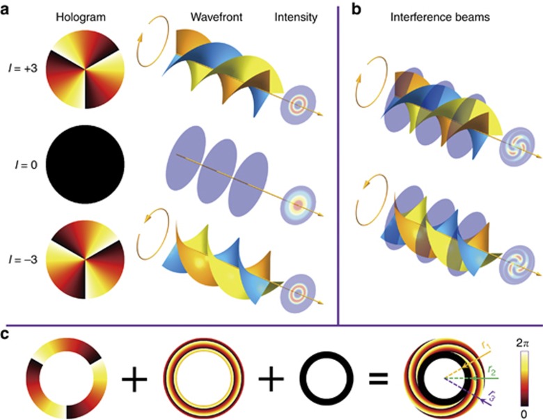
An optical vortex can be conveniently created after a plane wave is reflected from an SLM, which is loaded with an azimuthal phase hologram7, 23. A CGH with an azimuthal phase (lφ)mod 2π corresponds to the helical phase wavefronts and a 2D ‘doughnut’-shaped intensity distribution, as illustrated in Figure 1a. φ is the azimuthal angle around the optical axis, and topological charge l can be any positive or negative integer. For a given l, the vortex beam has l intertwined helical phase fronts, which has left-handedness (or right-handedness) with positive (or negative) l, and a particular annular intensity profile, whose radius increases with l. Specially, when l is zero, the SLM with an equiphase distribution CGH acts as a mirror, and the reflected laser beam is a plane wave23. The topological charge l, or the state of OAM, of optical vortices can be visually revealed by interference with a reference beam24, 25. Figure 1b shows that an optical vortex interfered with a plane wave generates a spiral intensity interferogram on the focal plane. There are l spiral lobes in the interference patterns with topological charge l, and the sign of topological charge l determines the handedness of the spiral lobes. However, the conventional interference setup, where a Gaussian reference beam is split and then superimposed with the OAM beam, generally requires steady mechanics because the interference pattern is sensitive to the phase of the Gaussian reference beam25, 26. To avoid variation of the relative phase between the optical vortices and the Gaussian reference beam, we adopt SLM to generate stable spiral patterns through copropagating the interference of optical vortices and plane waves for the first time.
Figure 1.
Holographic generation of a 3D spiral optical field by coaxial interference of a vortex beam and a plane wave. (a) Illustration of the optical vortex holograms with topological charge l=3 (top panels) and −3 (bottom panels) and the corresponding optical helical phase wavefronts and ‘doughnut’-shaped intensity distributions. A regular Gaussian beam hologram (middle panels) with l=0 has a plane wavefront. (b) Interfering a vortex beam (l=3 or −3) with a plane wave results in a spiral pattern. (c) Azimuthal phase hologram (l=3) superimposed with annular zero equiphase in the central area. A radial shift phase tilts the optical vortex to interfere with the plane wave.
Figure 1c explains the procedure to design IVH with l=3, consisting of both an azimuthal phase and an equiphase for 3D spiral optical fields. The annular hologram of an optical vortex superimposes zero phase value in the central area, which is regarded as a plane wave, and a radial shift on the vortex hologram realizes interfering with the plane wave27. The IVHs can be presented as
 |
where ∅(r, φ) is the transverse phase distribution on the IVHs, r is the radial distance from the hologram center and R is the radial shift value, which determines the shift angle of the vortex beam. The size of the central zero area is tailored accurately to obtain a perfect intensity pattern (Supplementary Figs. S1 and S3).
Experimental and theoretical intensity distributions of the annular optical vortex and IVBs with different spiral lobes
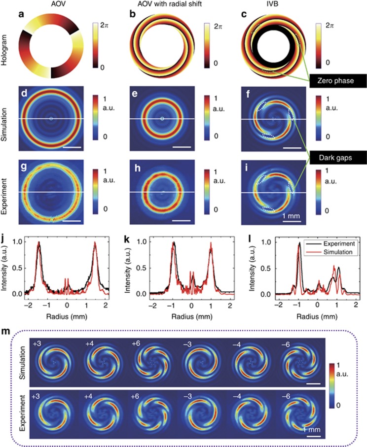
An annular optical vortex superimposed with a radial shift phase can shrink the ‘doughnut’-shaped intensity profiles to interfere with the plane wave (Supplementary Fig. S2). The IVBs generated by IVHs feature the interference patterns of the optical vortices and plane wave references (Figure 2a–2l). Figure 2m shows the simulated and detected optical intensity distributions of IVBs with varying topological charges l=±3, ±4 and ±6. The observed intensity profiles of the IVBs are captured using a charge-coupled device on plane N, where the distance from L3 is d=350 mm (Figure 3a). These measurements are in good agreement with the corresponding simulations. The topological charges of the IVBs are easy to distinguish without another beam for interference. Furthermore, the radii of interference patterns with different topological charges are almost the same, except for the dark gaps on the ‘doughnut’-shaped profile (Figure 2f and 2i). The dark gaps with zero intensity correspond to the zero phase area of the azimuthal phase in IVHs, the number of dark gaps represents the magnitude of the topological charge and the twist direction indicates its sign.
Figure 2.
Experimental and theoretical intensity distributions of an annular optical vortex and IVBs with different spiral lobes. Annular azimuthal hologram (a) has the simulated (d) and experimental (g) ‘doughnut’-shaped intensity distributions. Annular azimuthal hologram with a radial shift (b) has a constringent ‘doughnut’-shaped intensity profile, as seen from the simulation (e) and experiment (h). IVH (c) has simulated (f) and experimental (i) spiral shape intensity profiles. (j–l) Comparison of vertical cuts of the intensity distributions of simulation and experiment corresponding to a–c. (m) Simulated intensity profiles and observed results of IVBs with topological charge l=±3, ±4 and ±6. The dark gaps in the simulated (f) and experimental (i) intensity patterns of the IVBs correspond to the zero phase in the hologram c.
Figure 3.
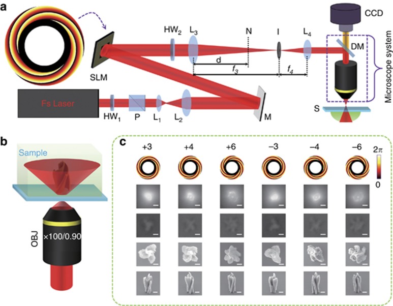
SLM-based experimental setup for 3D chiral microstructures in isotropic material. (a) The femtosecond laser is expanded using a telescope (lenses L1–L2) to match the aperture of the SLM, after its polarization and power are controlled using a half-wave plate (HW1) and a polarizer (P). The Gaussian beam, reflected by a mirror (M), is modulated by an SLM, which displays a designed hologram. Subsequently, the desired first-order diffraction beam is selectively introduced into the microscope system via an iris (I) positioned at the focal plane of the lenses (L3 and L4). A half-wave plate (HW2) behind the SLM is used to rotate the polarization. Experimental setup: DM, dichroic mirror; S, sample. (b) Finally, the diffracted beam is focused onto a sample located under the focal plane of a × 100 microscope objective (OBJ), and a chiral microstructure is achieved. (c) The beam, which is modulated by designed holograms (first row) with different topological charges that can be positive or negative, illuminates the sample. Then, the intensity pattern (second row) and optical micrograph of the polymer (third row) can be measured using a charge-coupled device. After developing, top-view (fourth row) and 45° tilted (fifth row) SEM images of chiral microstructures are realized. (Scale bar, 2 μm)
SLM-based experimental setup for 3D chiral microstructures in isotropic material
The experimental setup used to fabricate chiral microstructures is depicted in Figure 3a. We use a femtosecond laser working at a wavelength λ=800 nm, which is adjusted to be a linearly polarized Gaussian beam. The beam reflected from the SLM displaying IVH has helical phase wavefronts and spiral lobe patterns. To remove the spiral patterns from other diffraction orders and to control the desirable spatial shape of the reflecting beam, an annular tilted shift phase hologram is added to the holograms (Supplementary Fig. S4)28. The sample is inverted under a × 100 objective lens (NA 0.9) of the microscope system (see the Materials and Methods section). The exposure time is 4 s, and the laser power measured after the iris is 100 mW. A 3D chiral microstructure is polymerized in the photoresist on the defocused area, as illustrated in Figure 3b. A lower laser power is chosen to illuminate the sample to obtain an unambiguous fluorescent image. The induced fluorescent images captured using a charge-coupled device, consist of a central bright dot and a ‘doughnut’-shaped pattern, which are coincident with the focused patterns from the plane wave and the optical vortex using an objective lens (Figure 3c). A spiral pattern with l(±3, ±4 and ±6) lobes, whose direction is determined by the sign of the topological charge, is evident in the polymer after illuminating with IVBs. The diameter of the spiral pattern is increases with increasing topological charge (Supplementary Fig. S6). More details of the chiral microstructure topography can be detected after development. The distinct chiral microstructures with surface wrinkles have l spiral lobes (top-view) and helices (45° tilted view), as observed in the SEM images. These chiral microstructures fabricated in an isotropic polymer by interfering vortex beams with different polarizations do not have obvious differences (Supplementary Fig. S7).
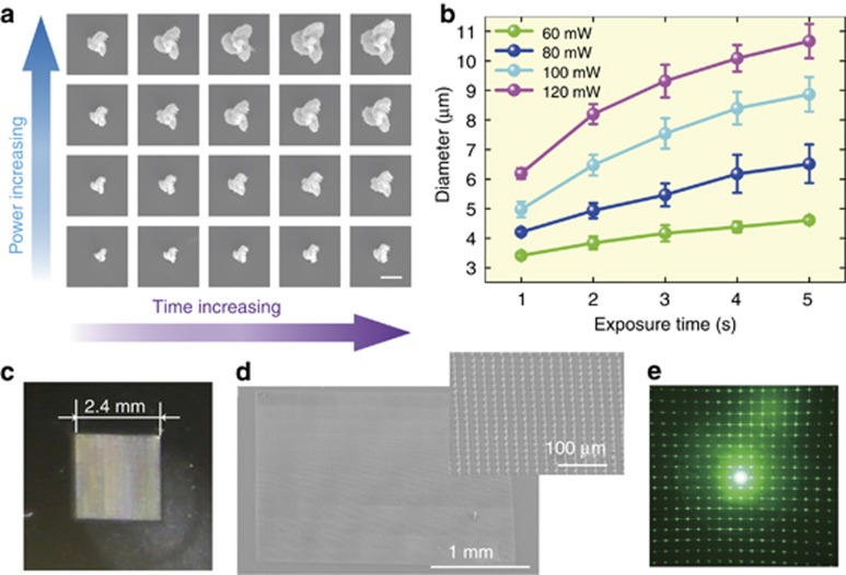
Precise control over the shape and size of the chiral microstructures is needed to optimize the fabrication parameters. As shown in Figure 4a and 4b, a series of chiral microstructures with three spiral lobes can be produced with a fixed laser intensity and varying exposure time from 1 to 5 s. Although the diameters of the chiral structures increase with increasing laser power or exposure time, the structures remain chiral with l spiral lobes. Their diameter and height, maintaining both spiral lobes and chirality, can reach 3.4 and 9.2 μm, respectively (Supplementary Fig. S8). An array of chiral microstructures with three spiral lobes in a 2.4 mm × 2.4 mm square area is fabricated rapidly with an irradiation power of 120 mW and an exposure time of 1 s (Figure 4c–4e). The total time is 4 h, in contrast to the 20 days required by conventional point-to-point scanning. When a 532 nm excitation light irradiates the array, a uniform spot pattern is diffracted on the received screen, indicating remarkable homogeneity of the large-area chiral microstructure array.
Figure 4.
Large-area uniform chiral microstructures with controllable sizes using the optimized parameters. (a) SEM images of chiral microstructures with three spiral lobes achieved for different values of laser power and exposure time. (Scale bar, 5 μm) (b) Quantitative study of the diameter of the chiral microstructure as a function of exposure time and power. Error bars are the s.d. of three fabrications using the same parameters. (c) Optical image of a square area with 2D grating-like chiral microstructures has structural color, with a period of 20 μm. (d) SEM image of the arrayed chiral microstructures; inset is a magnified view. (e) Diffraction pattern fired by a laser with wavelength of 532 nm on the square area. s.d.: standard deviation.
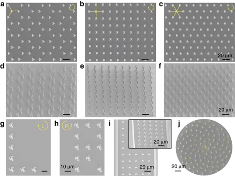
More complicated arrangements with three-, four- and six-fold symmetric patterns, with 3, 4 and 6 spiral lobes, respectively, are achieved by controlling both holograms and positions29 (Figure 5a–5f). Four seconds are required to fabricate a chiral microstructure with 100 mW of power, and the total time for fabricating a 200 μm × 200 μm square is <8 min. Microstructure arrays with inverse chirality can be readily produced on the same substrate by changing the holograms, such as the letter ‘L’ with left-handedness and the letter ‘R’ with right-handedness, as illustrated in Figure 5g and 5h. The desired pattern can be written on a flat surface or nonplanar microchannel30 with precise location using a nanopositioning stage (Figure 5i). The formation of a Fibonacci number pattern with left-handed microstructures can be grouped into 13 counterclockwise spirals31 (Figure 5j). These images verify that IVB-based microfabrication is a robust and versatile approach to build 3D chiral microstructures arrayed in any 2D pattern.
Figure 5.
Diverse patterns prepared by chiral microstructures on flat and complex surfaces. (a–c) Top view and (d–f) 45° tilted SEM images of three-, four- and six-fold symmetric patterns with three, four and six spiral lobes, respectively. (g, h) SEM images of microscale letters of ‘L’ (left) and ‘R’ (right) arranged with left- and right-handed microstructures, respectively. (i) Chiral microstructures integrated in a nonplanar substrate (inset: 45° tilted SEM image). (j) A Fibonacci number pattern fabricated with topological charge l=3.
Orientation-controlled rotation of chiral microstructures by changing the phase value of the plane wave
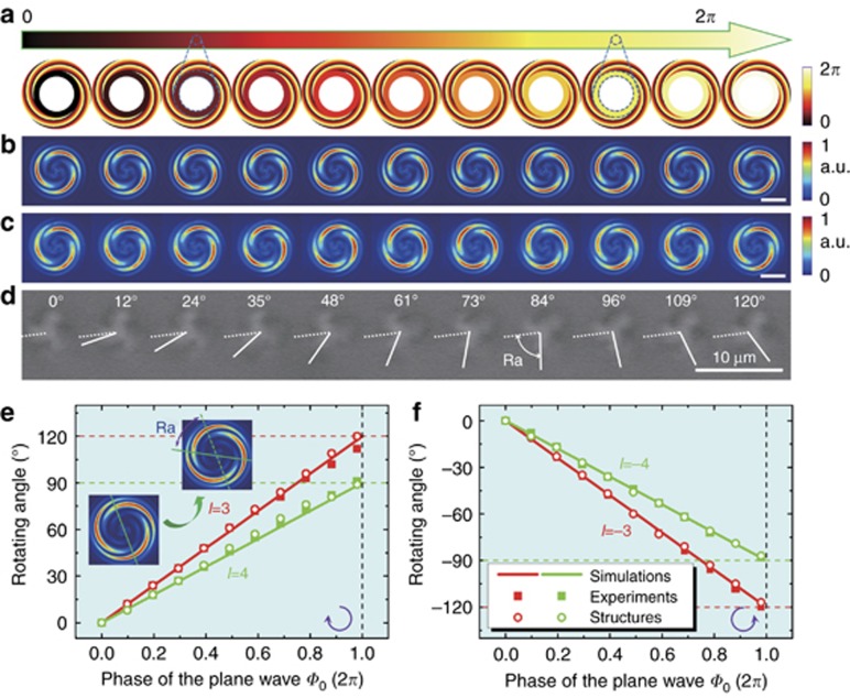
As a common technique to visualize the OAM state of optical vortices, interference patterns can change the sense of rotation with the relative phase between the two interference beams. Specifically, objects can be trapped within the interference pattern of an optical vortex and a plane wave, consisting of l spiral lobes, which is one way to simultaneously orient multiple symmetric objects26. Since there are no free-space optics for creating a plane wave reference, the interference patterns are stable in our interfering system. Moreover, theoretically, we can precisely rotate the chiral microstructure to any angle about its axis by changing the phase value of the plane wave with topological charge l=3 (Figure 6a). The phase value can be modified by changing the gray value in the CGHs rather than mechanically tailoring the length of one arm of the interferometer. As dark gaps are generated by the IVBs, where the azimuthal phase value is equal to the equiphase value on the IVHs, they can be rotated by modifying the equiphase value. As a result, the inverse spiral lobes rotate visually on the optical field. Both the simulation (Figure 6b) and measurement (Figure 6c) of the IVB intensity profiles rotate the same angles with varying phase value of the plane waves. Chiral microstructures fabricated by focused IVBs under the objective lens maintain the rotating angle (Figure 6d). The equivalent phase area between the azimuthal phase and equiphase in the IVHs is rotated by varying the phase of the interfering plane wave from 0 to 2π. The rotating angle of spiral lobes increases linearly with the phase value of the plane wave by
Figure 6.
Orientation-controlled rotation of chiral microstructures by changing the phase value of the plane wave. (a) The phase of the interfering plane wave increases from 0 to 2π, as indicated by an arrow with a color gradient. The simulated intensity patterns (b) rotate in coincidence with the measurements (c). (Scale bar, 1 mm) (d) Rotation of the chiral microstructures with l=3. Rotating angle (Ra) of the simulated and measured intensity patterns. The measured values of the microstructures are a function of the phase value of the plane wave with l=3, 4 (e) and −3, −4 (f). The solid line represents the simulated Ra. The squares and circles denote the measurements of the optical intensity distributions and chiral microstructures, respectively. Vertical dashed lines indicate ∅0=2π, for which the largest rotating angles are generated.
where Ra is the rotating angle and ∅0 is the equiphase value (Figure 6e and 6f). An axisymmetric chiral microstructure fabricated with topological charge l has spiral lobes with l-fold symmetry, causing a full rotation of 360° on the substrate.
Helical characterization and mechanism analysis of the 3D chiral microstructures
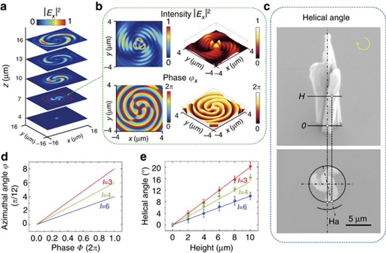
The chiral microstructures under illumination with IVBs feature l spiral lobes on the transverse section and helices on the optical axis. The l spiral lobes are associated with interference patterns, which have the same rotating angle in Equation (6). There is no mass transport in this process because the chirality is independent of the exposure time and applied power (Figure 4). We cannot discuss the chirality by analyzing the transverse optical field only on the focal plane for 3D microstructures. Starting from this consideration, we have simulated the intensity profiles of an IVB focused using a × 100 objective lens at different distances from the focal plane, as illustrated in Figure 7a. The intensity and phase distribution of the Ex component at distance z=7 μm below the focal plane of the objective lens are shown in Figure 7b, in both 2D and 3D formats. Three spiral lobes are distributed in three-fold symmetry, and the interference fringes are generated radially, corresponding to the surface wrinkles of chiral microstructures. To understand the helices of chiral microstructures, Figure 7c shows the definition of the helical angle of a structure with remarkable chirality. As no other device changes the azimuthal phase distribution in the beam propagation, the azimuthal optical phase gradients of the optical vortices remain. The azimuthal phase distributions of the optical vortices vary by ∅=lφ (Figure 7d). Three spiral lobes gradually shrink to the optical axis without revolving in the transverse intensity profile far from the focal plane. Upon arriving at the helical phase center, the spiral lobes start to rotate predominately around the axis, with a large azimuthal phase gradient (Supplementary Figs. S11 and S12). Due to the azimuthal phase gradient, the spiral lobes rotate through a helical angle (Ha) in the transverse estimated by
Figure 7.
Helical characterization and mechanism analysis of 3D chiral microstructures. (a) Simulated intensity distribution images of the Ex component in 3 μm steps along the z-axis under the OBJ. (b) The intensity and phase profiles are simulated on the plane, z=7 μm from the focal plane of OBJ. (c) The helical angle (Ha) of the chiral microstructure is defined as the rotating angle of cross-sections along the z-axis. (d) Azimuthal angle versus phase value in the phase profile of optical vortices with l=3, 4 and 6, respectively. (e) The helical angles (Has) are measured as a function of height (H), shown as points, and are compared to the values in Equation (7), shown as solid lines. The error bars are the s.d. of three fabrications using the same parameters.
where C is a constant and H is the height of the chiral microstructures (Figure 7e), which means that the helices of chiral microstructures Ha/H∝1/l. Therefore, the interference between optical vortices and plane waves generates an intensity pattern consisting of l spiral lobes, and the helical phase wavefronts keep them winded. The coaxial interference with the SLM in our experiments prevents the undesirable rotation of the spiral lobes of chiral microstructures by the relative phase in an unstable environment. As a result, we demonstrate that chiral microstructures with l spiral lobes record the information of not only the intensity patterns but also the helical phase wavefronts.
Conclusions
We demonstrate 3D chiral microstructures with large area and high precision fabricated in isotropic polymer by developing the coaxial interference of OAM beams and plane waves for the first time. The coaxial interference beams are realized using a simple and effective system to reflect IVBs with integrated IVHs displayed on an SLM. 3D spiral optical fields are produced by helical phase wavefronts twisting the interfering spiral patterns, and 3D chiral microstructures with controllable spiral lobes and orientations are polymerized after illumination of IVBs. By designing the IVHs on SLM, chiral microstructures with controllable rotation angles can be stably achieved. We ascribe the spiral lobes to the interfering patterns and the chirality to the action of OAM. Our findings provide a new promising technique to fabricate chiral microstructures in an isotropic polymer with a single pulse. Large-area arrays of chiral microstructures up to 1 cm2 can be fabricated in 5 min with this technology by using a high-power laser. Furthermore, the uniform arrangement of chiral microstructures has potential to manufacture chiral metamaterials with applications in optoelectronic devices, analytical chemistry and circular dichroism spectroscopy32. As a method to generate flexibly stable interference patterns of optical vortices and plane waves, this technology also creates an innovative method for optical tweezers and optical communications.
Author contributions
JN, YH and CZ designed the research; JN, BX and CW performed the research; JN, LY and YH designed the CGHs; DW, JL, ZL and JC analyzed the data; and JN, YH and DW wrote the manuscript.
Acknowledgments
This work was supported by National Natural Science Foundation of China (no. 51675503, 61475149, 51405464, 61675190 and 51605463), the Fundamental Research Funds for the Central Universities (no. WK2480000002), the China Postdoctoral Science Foundation (no. 2016M590578 and 2016M602027), the Chinese Academy of Sciences Instrument Project (YZ201566), and the ‘Chinese Thousand Young Talents Program’.
Footnotes
Note: Supplementary Information for this article can be found on the Light: Science & Applications’ website (http://www.nature.com/lsa).
The authors declare no conflict of interest.
Supplementary Material
References
- Litchinitser NM. Structured light meets structured matter. Science 2012; 337: 1054–1055. [DOI] [PubMed] [Google Scholar]
- Curtis JE, Grier DG. Structure of optical vortices. Phys Rev Lett 2003; 90: 133901. [DOI] [PubMed] [Google Scholar]
- Grier DG. A revolution in optical manipulation. Nature 2003; 424: 810–816. [DOI] [PubMed] [Google Scholar]
- Padgett M, Bowman R. Tweezers with a twist. Nat Photonics 2011; 5: 343–348. [Google Scholar]
- Bozinovic N, Yue Y, Ren YX, Tur M, Kristensen P et al. Terabit-scale orbital angular momentum mode division multiplexing in fibers. Science 2013; 340: 1545–1548. [DOI] [PubMed] [Google Scholar]
- Wang J, Yang JY, Fazal IM, Ahmed N, Yan Y et al. Terabit free-space data transmission employing orbital angular momentum multiplexing. Nat Photonics 2012; 6: 488–496. [Google Scholar]
- Ambrosio A, Marrucci L, Borbone F, Roviello A, Maddalena P. Light-induced spiral mass transport in azo-polymer films under vortex-beam illumination. Nat Commun 2012; 3: 989. [DOI] [PMC free article] [PubMed] [Google Scholar]
- Toyoda K, Miyamoto K, Aoki N, Morita R, Omatsu T. Using optical vortex to control the chirality of twisted metal nanostructures. Nano Lett 2012; 12: 3645–3649. [DOI] [PMC free article] [PubMed] [Google Scholar]
- Allen L, Beijersbergen MW, Spreeuw RJC, Woerdman JP. Orbital angular momentum of light and the transformation of laguerre-gaussian laser modes. Phys Rev A 1992; 45: 8185–8189. [DOI] [PubMed] [Google Scholar]
- Toyoda K, Takahashi F, Takizawa S, Tokizane Y, Miyamoto K et al. Transfer of light helicity to nanostructures. Phys Rev Lett 2013; 110: 143603. [DOI] [PubMed] [Google Scholar]
- Zhang SJ, Li Y, Liu ZP, Ren JL, Xiao YF et al. Two-photon polymerization of a three dimensional structure using beams with orbital angular momentum. Appl Phys Lett 2014; 105: 061101. [Google Scholar]
- Yang L, El-Tamer A, Hinze U, Li JW, Hu YL et al. Two-photon polymerization of cylinder microstructures by femtosecond Bessel beams. Appl Phys Lett 2014; 105: 041110. [Google Scholar]
- Deubel M, von Freymann G, Wegener M, Pereira S, Busch K et al. Direct laser writing of three-dimensional photonic-crystal templates for telecommunications. Nat Mater 2004; 3: 444–447. [DOI] [PubMed] [Google Scholar]
- Wu D, Xu J, Niu LG, Wu SZ, Midorikawa K et al. In-channel integration of designable microoptical devices using flat scaffold-supported femtosecond-laser microfabrication for coupling-free optofluidic cell counting. Light Sci Appl 2015; 4: e228; doi:10.1038/lsa.2015.1. [Google Scholar]
- Gansel JK, Thiel M, Rill MS, Decker M, Bade K et al. Gold helix photonic metamaterial as broadband circular polarizer. Science 2009; 325: 1513–1515. [DOI] [PubMed] [Google Scholar]
- Zhang CC, Hu YL, Li JW, Lao ZX, Ni JC et al. An improved multi-exposure approach for high quality holographic femtosecond laser patterning. Appl Phys Lett 2014; 105: 221104. [Google Scholar]
- Lin H, Gu M. Creation of diffraction-limited non-airy multifocal arrays using a spatially shifted vortex beam. Appl Phys Lett 2013; 102: 084103. [Google Scholar]
- Hu YL, Chen YH, Ma JQ, Li JW, Huang WH et al. High-efficiency fabrication of aspheric microlens arrays by holographic femtosecond laser-induced photopolymerization. Appl Phys Lett 2013; 103: 141112. [Google Scholar]
- Goodman JW. Introduction to Fourier Optics. 2nd edn. New York: McGraw-Hill; 1996. [Google Scholar]
- Richards B, Wolf E. Electromagnetic diffraction in optical systems. II. Structure of the image field in an aplanatic system. Proc R Soc A 1959; 253: 358–379. [Google Scholar]
- Hao X, Kuang CF, Wang TT, Liu X. Effects of polarization on the de-excitation dark focal spot in STED microscopy. J Opt 2010; 12: 115707. [Google Scholar]
- Zhao YQ, Edgar JS, Jeffries GDM, McGloin D, Chiu DT. Spin-to-orbital angular momentum conversion in a strongly focused optical beam. Phys Rev Lett 2007; 99: 073901. [DOI] [PubMed] [Google Scholar]
- Zambrana-Puyalto X, Vidal X, Molina-Terriza G. Angular momentum-induced circular dichroism in non-chiral nanostructures. Nat Commun 2014; 5: 4922. [DOI] [PubMed] [Google Scholar]
- Karimi E, Schulz SA, De Leon I, Qassim H, Upham J et al. Generating optical orbital angular momentum at visible wavelengths using a plasmonic metasurface. Light Sci Appl 2014; 3: e167. [Google Scholar]
- Sun J, Moresco M, Leake G, Coolbaugh D, Watts MR. Generating and identifying optical orbital angular momentum with silicon photonic circuits. Opt Lett 2014; 39: 5977–5980. [DOI] [PubMed] [Google Scholar]
- Paterson L, MacDonald MP, Arlt J, Sibbett W, Bryant PE et al. Controlled rotation of optically trapped microscopic particles. Science 2001; 292: 912–914. [DOI] [PubMed] [Google Scholar]
- Mehmood MQ, Mei ST, Hussain S, Huang K, Siew SY et al. Visible-frequency metasurface for structuring and spatially multiplexing optical vortices. Adv Mater 2016; 28: 2533–2539. [DOI] [PubMed] [Google Scholar]
- Mirhosseini M, Malik M, Shi ZM, Boyd RW. Efficient separation of the orbital angular momentum eigenstates of light. Nat Commun 2013; 4: 2781. [DOI] [PubMed] [Google Scholar]
- Hu YL, Lao ZX, Cumming BP, Wu D, Li JW et al. Laser printing hierarchical structures with the aid of controlled capillary-driven self-assembly. Proc Natl Acad Sci USA 2015; 112: 6876–6881. [DOI] [PMC free article] [PubMed] [Google Scholar]
- Xu B, Du WQ, Li JW, Hu YL, Yang L et al. High efficiency integration of three-dimensional functional microdevices inside a microfluidic chip by using femtosecond laser multifoci parallel microfabrication. Sci Rep 2016; 6: 19989. [DOI] [PMC free article] [PubMed] [Google Scholar]
- Li CR, Zhang XN, Cao ZX. Triangular and Fibonacci number patterns driven by stress on core/shell microstructures. Science 2005; 309: 909–911. [DOI] [PubMed] [Google Scholar]
- Esposito M, Tasco V, Todisco F, Cuscunà M, Benedetti A et al. Triple-helical nanowires by tomographic rotatory growth for chiral photonics. Nat Commun 2015; 6: 6484. [DOI] [PMC free article] [PubMed] [Google Scholar]
Associated Data
This section collects any data citations, data availability statements, or supplementary materials included in this article.


