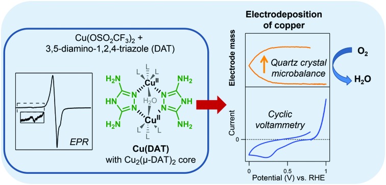
 The activity of the 3,5-diamino-1,2,4-triazole copper system for the oxygen reduction reaction was found to originate from an electrodeposition rather than the parent complex.
Abstract
Dinuclear CuII complexes bearing two 3,5-diamino-1,2,4-triazole (DAT) ligands have gained considerable attention as a potential model system for laccase due to their low overpotential for the oxygen reduction reaction (ORR). In this study, the active species for the ORR was investigated. The water soluble dinuclear copper complex (Cu(DAT)) was obtained by mixing a 1 : 1 ratio of Cu(OTf)2 and DAT in water. The electron paramagnetic resonance (EPR) spectrum of Cu(DAT) showed a broad axial signal with a g factor of 2.16 as well as a low intensity Ms = ±2 absorption characteristic of the Cu2(μ-DAT)2 moiety. Monitoring the typical 380 nm peak with UV-Vis spectroscopy revealed that the Cu2(μ-DAT)2 core is extremely sensitive to changes in pH, copper to ligand ratios and the presence of anions. Electrochemical quartz crystal microbalance experiments displayed a large decrease in frequency below 0.5 V versus the reversible hydrogen electrode (RHE) in a Cu(DAT) solution implying the formation of deposition. Rotating ring disk electrode experiments showed that this deposition is an active ORR catalyst which reduces O2 all the way to water at pH 5. The activity increased significantly in the course of time. X-ray photoelectron spectroscopy was utilized to analyze the composition of the deposition. Significant shifts in the Cu 2p3/2 and N 1s spectra were observed with respect to Cu(DAT). After ORR catalysis at pH 5, mostly CuI and/or Cu0 species are present and the deposition corresponds to previously reported electrodepositions of copper. This leads us to conclude that the active species is of a heterogeneous nature and lacks any structural similarity with laccase.
1. Introduction
Hydrogen is considered the fuel of the future as it can be produced from sustainable energy sources such as sunlight and wind. In a fuel cell, electricity can be regenerated by electrochemical oxidation of hydrogen at the anode (eqn (1)) and an oxygen reduction reaction (ORR) at the cathode (eqn (2)). Thus far, platinum is the catalyst of choice at the cathode.1 Nonetheless, platinum catalysts cannot operate at the thermodynamic equilibrium potential of water at 1.23 V versus the reversible hydrogen electrode (RHE) and require an additional energy input of approximately 400 mV. This limits the overall efficiency of the fuel cell.1–3 Moreover, platinum is too expensive and too scarce to be applied on a scale required for a sustainable hydrogen economy.4,5 Hence, viable alternatives must be found.
The family of multi-copper oxidases (MCOs) catalyzes the oxidation of various substrates while simultaneously reducing oxygen to water.6–8 An extensively studied MCO is laccase which bears a trinuclear copper ORR site consisting of type 2 (“normal copper”) and type 3 (dinuclear) copper nuclei.9 Electrochemical studies on immobilized laccase have shown that both dioxygen reduction as well as water oxidation are performed close to the equilibrium potential.10–16 How laccase is able to perform the ORR close to the equilibrium potential of water is still a very intriguing question.17,18
| H2 → 2H+ + 2e– E° = 0 V | 1 |
| O2 + 4H+ + 4e– → 2H2O E° = 1.23 V | 2 |
Synthetic laccase mimics are important for the elucidation of the mechanism wherein dioxygen can be reduced efficiently. Structural and electronic information of key intermediates in the activation of dioxygen by model copper complexes are very valuable references to explain the enzymatic process.19–24 Yet, the ORR performance of the majority of these copper based model systems is relatively unexplored.
The dinuclear copper complex bearing two 3,5-diamino-1,2,4-triazole (DAT) ligands25 is considered to be a benchmark system for the ORR as it has been proposed to be a very active synthetic catalyst.26 The onset potential for the ORR, when deposited on a carbon support, was claimed to be one of the highest reported yet for synthetic copper complexes; that is 0.86 V versus RHE at pH 13. For this reason, it was proposed that the structure and ORR activity of this copper complex make the complex an interesting model for laccase. Nonetheless, the mechanism wherein dioxygen is reduced has not been fully clarified yet.27–34 No detailed structure of the active species is known. This signifies the relevance of pinpointing the active structure of these species in order to be able to define any catalyst design principles for copper mediated ORR.
In this study, we have investigated the active species of the ORR mediated by the molecular DAT coordinated copper complex and found that not the complex but rather electrodeposited CuI and/or Cu0 appears to be the active species.
2. Experimental
2.1. General
Milli-Q Ultrapure grade water (>18.2 MΩ cm resistivity) was used for all experiments and for the preparation of aqueous solutions. All chemicals were bought from commercial sources and used without any further purification. 0.1 M aqueous electrolyte solutions were prepared from NaOH·H2O (TraceSelect ≥99.9995%, Fluka), NaClO4·H2O (EMSURE®, Merck), and 70% HClO4 (Suprapur®, Merck). The 0.03 M 2-(N-morpholino)ethanesulphonic acid (MES buffer, High Purity Grade, VWR) buffer contains 0.1 M NaClO4 to obtain a proper ionic strength and was adjusted to pH 5.2 using NaOH. A 0.04 M 7 Britton–Robinson buffer was prepared from H3PO4 (85%, Suprapur®, Merck), glacial acetic acid (Honeywell, ≥99.99%), and H3BO3 (Sigma Aldrich, ≥99.999%) and adjusted with NaOH to obtain the correct pH. The ionic strength was increased with 0.1 M NaClO4. Electrolytes containing DAT or a 1 : 1 mixture of Cu(OTf)2 and DAT (the complex that is formed by this mixture is further referred to as Cu(DAT)) were prepared from Cu(OTf)2 (Alfa Aesar) and/or 3,5-diamino-1,2,4-triazole (Acros). Generally, a 6.6 mM solution of these precursors was prepared by dissolving the appropriate amount of Cu(OTf)2 and/or DAT (simultaneously) in the electrolyte. Other concentrations have been obtained in a similar manner. Cu(DAT) solutions were always freshly prepared prior to the measurement because the solution is not stable over a prolonged period of time (Fig. S1, ESI†). Vulcan|Cu(DAT) was prepared according to the reported procedure26 (see ESI†).
pH measurements and titrations were performed with either a Hanna Instruments HI 4222 or a Radiometer PHM220 pH meter that were calibrated using standard IUPAC buffers. UV-Vis measurements were performed on a Varian Cary 50 UV-Vis spectrophotometer. Electron paramagnetic resonance (EPR) spectra were recorded on a Bruker EMXplus X-band spectrometer.
2.2. Electrochemical experiments
All electrochemical experiments apart from the rotating ring disk electrode (RRDE) experiments and electrochemical quartz crystal microbalance (EQCM) experiments were performed in custom-made single-compartment glass cells using a three-electrode set-up. All glassware used in electrochemical measurements was routinely cleaned by boiling in a 3 : 1 mixture of concentrated sulfuric and nitric acid. Prior to each experiment, the glassware was cleaned by at least twofold boiling and rinsing with Milli-Q water. Autolab PGSTAT 12, 204 and 128N potentiostats operated by NOVA software were used. All potentials are reported versus RHE.
All solutions were purged by argon (Linde, Ar 5.0) for at least 30 minutes prior to each experiment and the cell was kept under a flow of argon during the experiment. Oxygen-saturated solutions were prepared by purging the solution with O2 (Linde, O2 5.0) for at least 20 minutes and an oxygen atmosphere was sustained during the experiment.
The counter electrode was a large surface area gold wire that was flame annealed and rinsed with water prior to use. The reference electrode was a platinum mesh in H2 (Linde, H2 5.0) saturated electrolyte or a HydroFlex (GasKatel) electrode working at the same pH as the working electrode. Any unbuffered solutions were acidified with HClO4 to obtain the correct pH. The cell and reference electrode were connected via a Luggin capillary. The working electrode (WE) was either a pyrolytic graphite (PG) electrode or a gold electrode used in hanging meniscus configuration. PG was sanded with 600 and 1000 grit sandpaper followed by 10 minutes sonication in water prior to use. The gold working electrode was a gold plate that was cleaned prior to use by applying 10 V between the gold WE and a graphite counter electrode for 30 seconds in a 10% H2SO4 solution. This was followed by dipping the gold WE in 6 M HCl for 30 seconds. Next, the electrode was rinsed with water and flame annealed. The electrode was subsequently electrochemically polished by cyclic voltammetry (CV) between 0 and 1.75 V vs. RHE for 200 cycles at a 1 V s–1 scan rate in a 0.1 M HClO4 solution.
RRDE experiments were performed in a custom-made two-compartment cell using a three-electrode set-up. The counter electrode was used in a different compartment from the rotating disk electrode separated by a water permeable glass frit. A platinum (0.196 cm2), gold (0.196 cm2), pyrolytic graphite (0.12 cm2), glassy carbon (0.196 cm2) or copper disk (0.196 cm2) was used. All disk electrodes and the platinum ring were obtained from Pine Instruments and used in a ChangeDisk configuration using a Pine MSR rotator. Prior to use, the copper, gold, glassy carbon or platinum disk and platinum ring electrodes were mechanically polished for 2 minutes with subsequent rinsing and sonication in water for 10 minutes with 1.0, 0.3 and 0.05 micron alumina slurry respectively. The pyrolytic graphite disk was polished for 20 seconds with each alumina slurry. Next, electrochemical polishing was applied. The copper electrode was repeatedly electrochemically polished by applying 3 V for 10 seconds between the disk and a copper counter electrode in a 66% H3PO4 solution after which 0 V was applied for at least 30 seconds.35 Gold was cleaned by cyclic voltammetry as previously mentioned. Platinum was cleaned by cyclic voltammetry between 1.8 V and –0.2 V at 500 mV s–1 for 50 cycles in a 0.5 M H2SO4 solution.
EQCM experiments were performed in an Autolab 3 ml Teflon EQCM cell using an Autolab gold EQCM electrode (0.35 cm2) as working electrode that consists of a 200 nm gold layer deposited on a quartz crystal. A modified RHE reference electrode was used which prevents interference of continuous hydrogen bubbling to the sensitive microbalance signal.36
2.3. X-ray photoelectron spectroscopy
X-ray photoelectron spectroscopy (XPS) was performed on a Thermo Scientific K-Alpha spectrometer equipped with a monochromatic small-spot X-ray source and a double focusing hemispherical analyzer with a 128-channel delay line detector. Spectra were obtained by using an aluminum anode (Al Kα = 1486.6 eV) operated at 72 W and a spot size of 400 μm. Survey scans were measured at constant pass energy of 200 eV, and high-resolution scans of the separate regions were measured at 50 eV pass energy. The background pressure of the ultra-high vacuum (UHV) chamber was 2 × 10⁻⁸ mbar. Sample charging was compensated for by the use of an electron flood gun, and binding energy (BE) calibration was done by setting the C 1s peak of sp3 (CH, CC) carbon to BE (C 1s) = 284.8 eV. Electrode samples for XPS analysis with electrochemical deposition from Cu(DAT) were prepared by either cyclic voltammetry (CVAu|Cu(DAT) and CatAu|Cu(DAT), PG|Cu(DAT)) or chronoamperometry (CAAu|Cu(DAT)). Further details of the preparation of these samples can be found in ESI.† After modification by cyclic voltammetry, oxygen reduction catalysis was performed with CatAu|Cu(DAT) before subjecting the electrode to XPS analysis. The electrodes were consistently kept under an inert atmosphere during transfer, handling and introduction to the XPS apparatus. For sample CatAu|Cu(DAT), no special care was taken to prevent contact with air. CatGC|Vulcan|Cu(DAT) for XPS analysis was prepared by dropcasting Vulcan|Cu(DAT) onto a freshly polished GC electrode (0.07 cm2) according to the reported procedure.26
The XP spectra of the powders Vulcan|Cu(DAT) and Cu(DAT) were obtained by containing the powder in a powder sample holder (ThermoScientific). The Cu(DAT) powder was obtained from a 6.6 mM solution of a 1 : 1 ratio of Cu(OTf)2 and DAT in water. A green powder could be retrieved after removing water under reduced pressure.
3. Results and discussion
3.1. Complex characterization by electron paramagnetic resonance and UV-Vis spectroscopy
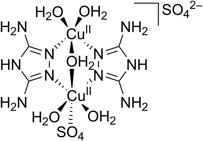
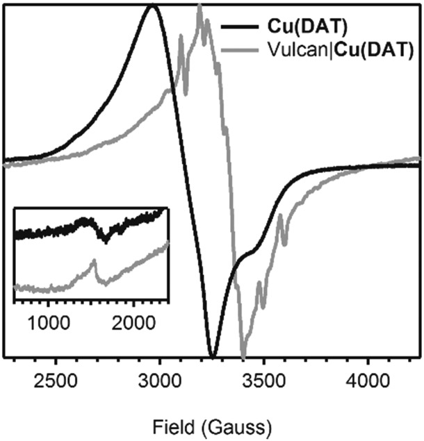
It was shown in previous studies that the structure of the DAT coordinated copper complex is strongly dependent on the method wherein it is prepared.25 The first crystal structure of a dinuclear copper complex was obtained by Aznar et al.25 Crystals of [Cu2(DAT)2(μ-OH2)(H2O)4(SO4)](SO4)·3.5H2O (Fig. 1) were obtained from the supernatant of a poorly soluble 1 : 1 mixture of CuSO4 and DAT. However, when CuCl2 was added to the suspension, a trinuclear species with a bridging sulfate anion was also found. Our first goal was to obtain a water-soluble dinuclear copper complex with DAT and to fully establish its structure in solution by several spectroscopic techniques. The solubility of the complex was significantly enhanced when anions such as triflate (OTf–) or perchlorate (ClO4–) were used instead of sulfate. Fig. 2 shows the electron paramagnetic resonance (EPR) spectrum of an aqueous solution containing a 1 : 1 ratio of Cu(OTf)2 and DAT. The complex that is formed by this mixture will be further referred to as Cu(DAT). A broad axial signal, corresponding to the triplet state, is observed at g = 2.16 consistent with the solid-state spectrum of [Cu2(DAT)2(μ-OH2)(H2O)4(SO4)](SO4)·3.5H2O25 and typical for a Cu2(μ-triazole)2 core.37–42 In addition, the lack of observable hyperfine interactions is a common feature for these compounds. Moreover, the characteristic weak half field signal corresponding to the forbidden Ms = ±2 transition was observed, belonging to the thermally populated S = 1 state of the dinuclear CuII species at temperatures above 20 K. The CuII sites are antiferromagnetically coupled (S = 0) in the ground state below 20 K.25 No signals of a S = 1/2 species, and in particular Cu(OTf)2, were observed43 This suggests that complete product formation has taken place and that Cu(DAT) is indeed a water soluble copper complex with the same Cu2(μ-DAT)2 core structure as [Cu2(DAT)2(μ-OH2)(H2O)4(SO4)](SO4)·3.5H2O. Structurally, it will thus only differ at the position of the sulfate anions. These positions will most likely be taken up by triflate, H2O, OH– or buffer. A green solid could be obtained from a Cu(DAT) solution by removing water under reduced pressure. The EPR spectrum of the powder showed the same characteristic features as compared to Cu(DAT) in solution (Fig. S2, ESI†) suggesting that the structure of Cu(DAT) is retained upon the removal of water. The structure of Cu(DAT) in solution was further validated by the observation of two distinctive peaks in the corresponding UV-Vis spectrum (Fig. S3b, ESI†). The 380 nm absorption correlates to either a charge-transfer band or a high-energy absorption of the CuII dimer. The exact assignment of this band has been under debate.25,41,42,44,45 In addition, a broad signal was observed at circa 740 nm arising from the d–d transition of copper.
Fig. 1. The structure of [Cu2(DAT)2(μ-OH2)(H2O)4(SO4)](SO4)·3.5H2O as determined by X-ray crystallography by Ferrer and co-workers.25.
Fig. 2. A superimposed and normalized EPR spectrum of a 0.02 M aqueous solution of a 1 : 1 mixture of Cu(OTf)2 and DAT (in black, obtained at 9.36 GHz) and a normalized solid state spectrum of Vulcan|Cu(DAT) (in grey, obtained at 9.37 GHz). The inset depicts a zoom of the spectra between 600 and 2400 Gauss. Both spectra were obtained at 77 K.
The stability and solubility of Cu(DAT) is very susceptible to changes in the conditions applied. A Cu(DAT) solution is not stable over prolonged periods of time (Fig. S1, ESI†) and therefore must always be freshly prepared. An aqueous solution of 6.6 mM DAT and Cu(OTf)2 in water or 0.1 M NaClO4 has a pH of 4.8 due to the formation of the Cu(DAT) complex. Upon protonation of the ligand (pKa of HDAT+ is 4.4),46–48 the Cu2(μ-DAT)2 core is disrupted (Fig. S3, ESI†). At high pH, an insoluble coordination polymer is formed (Fig. S4, ESI†) as is common for aqueous copper complexes.49–51 Likewise, changing DAT : Cu(OTf)2 ratios has a large effect as well (Fig. S5–S8, ESI†). The instability of a Cu(DAT) solution affects the tolerance towards buffers. Only the Good's buffer 2-(N-morpholino)ethanesulfonic acid (MES) was found suitable as it did not disrupt the Cu2(μ-DAT)2 core (Fig. S9 and S10, ESI†) and has a buffering capacity close to pH 4.8.52–54
3.2. Electrochemical quartz crystal microbalance experiments
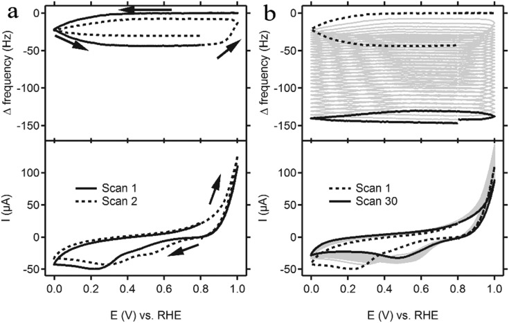
Cyclic voltammetry (CV) was performed with the same concentration (6.6 mM) Cu(DAT) as the UV-Vis experiments in a 0.1 M NaClO4 solution to keep conditions identical. Redox couples that are typically found for homogeneous species were not observed (Fig. 3). Instead, a broad cathodic peak from 0 to 0.8 V was observed as well as an anodic peak with an onset at 0.8 V. Electrochemical quartz crystal microbalance (EQCM) experiments were employed to investigate whether deposition of material on the electrode takes place and thus whether the active species is actually heterogeneous.55–57 In EQCM experiments, a gold-deposited quartz crystal is used which is oscillated during the electrochemical experiment. Frequency changes of this oscillation can be related directly to the change in mass of the electrode.58 A decrease in the observed frequency corresponds to an increase in mass. The EQCM data for Cu(DAT) show a decrease in frequency when the cathodic region is reached during repeated CV scans (Fig. 3a). Starting at 0.8 V, a typical scan begins with a positive sweep towards 1.0 V. An anodic peak with an onset of 0.9 V can be observed. This peak was also found in a 6.6 mM solution of DAT in the absence of Cu(OTf)2 (Fig. S11, ESI†) and is thus related to the oxidation of the ligand. When 1.0 V is reached in the first scan, a negative sweep is started and a broad cathodic peak is observed between 0.3 and 0 V. Simultaneously, a decrease in frequency, thus increase in mass, is observed suggesting that the electrochemical reduction triggers deposition of material on the electrode. In subsequent scans, the anodic peak has shifted to 0.8 V and is accompanied by loss of part of the deposition. Also, the cathodic region shifts to 0.5 V. Fig. 3b shows that after multiple scans, the CV apprehends a stable shape and the overall mass has increased significantly. Thus, a deposition is formed on the electrode by performing CV in this potential window. Likewise, the deposition can be formed potentiostatically when a potential of 0.2 V is applied (Fig. S12, ESI†). Hence, the oxidative events above 0.8 V are not required for the deposition to occur. Moreover, the activity towards the ORR is roughly the same for electrodes modified by CV or chronoamperometry (Fig. S13, ESI†). Expanding the potential window up to 1.3 V strips off most of the deposition in one single scan (Fig. S14, ESI†).
Fig. 3. A cyclic voltammogram (bottom panel) of a gold electrode in a 0.1 M NaClO4 solution (pH 4.8) containing 6.6 mM of a 1 : 1 mixture of Cu(OTf)2 and DAT performed at a scan rate of 100 mV s–1. The measurement was combined with a quartz crystal microbalance experiment (top panel). For clarity, only the first two scans are shown in (a) whereas (b) shows the full measurement of 30 scans.
3.3. Rotating ring disk electrode experiments
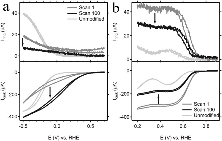
The catalytic activity of the deposition of Cu(DAT) was investigated using rotating ring disk electrode (RRDE) experiments. The activity was studied at both pH 5.2 and pH 13 for the reason that we found that the Cu(DAT) complex is stable at pH 5.2 but the highest activity has previously been reported at pH 13.26,28–30 For these tests, a pyrolytic graphite (PG) working electrode was chosen since gold is active in the same potential window for the ORR (Fig. S15, ESI†) compared to Cu(DAT) and a clear distinction between activity from gold and Cu(DAT) cannot be made. Nevertheless, the electrochemistry of Cu(DAT) on PG shows qualitatively the same CV as on gold (Fig. S16, ESI†). As mentioned previously, MES was used as buffer as it leaves the Cu2(μ-DAT)2 core intact. PG|Cu(DAT) was prepared by cyclic voltammetry between 0 and 1 V for 30 cycles at a 100 mV s–1 scan rate in a 0.1 M NaClO4 solution of pH 4.8 containing Cu(DAT) followed by thorough rinsing with water. At pH 5.2, the onset for the ORR on a PG|Cu(DAT) electrode was found to have shifted to a more positive potential with respect to unmodified PG (Fig. 4a). The observed current increased considerably upon repetitive potential cycling suggesting that further activation of the catalyst takes place. When the mass transport of dioxygen towards the electrode becomes the limiting factor, a peak current (plateau like region) is expected. However, such a diffusion-limited disk current was not observed. For PG electrodes, it is known that dioxygen is reduced via a 2-electron pathway to H2O2 or HOO– depending on pH (pKa of H2O2 is 11.8).59,60 These products are readily oxidized at the platinum ring electrode which is set at a fixed potential of 1.2 V. The ring current for PG|Cu(DAT) is significantly lower compared to unmodified PG. Moreover, the ring current decreases over time, which indicates an improvement of selectivity upon prolonged reaction times. An oxidizing ring current can already be observed prior to any ORR taking place at the disk (E > 0.5 V), suggesting that part of the ring current should be attributed to decomposition of the catalyst. Presumably, remnants of the DAT ligand are leaching away from the disk and are being oxidized on the ring as DAT is oxidized at potentials above 0.9 V (Fig. S11, ESI†). This is in line with a decreasing ratio of nitrogen to copper of the catalytic material at the disk as we will discuss later (Table 1). The observed increase in activity and selectivity at pH 5.2 is thus linked to decomposition of PG|Cu(DAT). This increase in activity over time can also be observed with non-rotating Au|Cu(DAT) electrodes (Fig. S13 and S18, ESI†).
Fig. 4. Shown here are the cyclic voltammograms (bottom panel) of the PG|Cu(DAT) disk rotated at 2000 rpm taken in an oxygen-saturated (a) 0.03 M MES buffer (pH 5.2) in 0.1 M NaClO4 and (b) 0.1 M NaOH (pH 13) solution. In the graphs, the 1st (dark grey line) and 100th scan (black line) of the CV of the disk taken at a 100 mV s–1 scan rate are shown. The light grey line depicts the current response of an unmodified PG disk electrode. In addition, the current response of the platinum ring, which was held at a potential of 1.2 V, is shown in the top panel.
Table 1. The ratio of nitrogen species with respect to the copper species of the modified electrodes and the reference compound Cu(DAT) as determined by XPS.
| Sample | Elemental ratio N : Cu a |
| Cu(DAT) | 5.6 |
| CVAu|Cu(DAT) | 3.0 |
| CAAu|Cu(DAT) | 2.6 |
| PG|Cu(DAT) | 4.2 |
| CatAu|Cu(DAT) | 2.1 |
| Vulcan|Cu(DAT) | 3.9 |
| CatGC|Vulcan|Cu(DAT) | 3.7 |
aThe full areas of all species in the N 1s region and in the Cu 2p3/2 region are used to determine the ratio.
At pH 13, the onset for dioxygen reduction with PG|Cu(DAT) was found to shift to a higher potential on the RHE reference scale compared to the ORR at pH 5.2 (Fig. 4b). Furthermore, a limiting disk current was observed. The activity rapidly decreases over the course of repeated CV scans, and stabilizes after circa 100 scans. A Koutecky–Levich analysis was conducted on the stable limiting catalytic current (see Fig. S17a and ESI†). 1.2 electrons are transferred during the electrochemical reduction of dioxygen by PG|Cu(DAT). Apparently, the selectivity of dioxygen reduction has shifted to the formation of mainly superoxide and partly peroxide species. This is further supported by the ring current that has a ratio of almost 100% with respect to the disk current (corrected for the collection efficiency, Fig. S17b, ESI†).
3.4. Electrode characterization with X-ray photoelectron spectroscopy
To determine the composition of the material that is deposited on the electrode, X-ray photoelectron spectroscopy (XPS) was performed on selected samples. An XPS spectrum of the well-defined Cu(DAT) powder was measured as reference for the dinuclear Cu2(μ-DAT)2 core found for Cu(DAT) in solution. In addition, three modified gold electrodes (CVAu|Cu(DAT), CAAu|Cu(DAT) and CatAu|Cu(DAT)) and a modified PG electrode (PG|Cu(DAT)) were prepared. Gold electrodes were used since pyrolytic graphite overlaps with the ligand carbon signals in the C 1s region. Both CVAu|Cu(DAT) and CatAu|Cu(DAT) were modified under the same conditions as the preparation of PG|Cu(DAT) using cyclic voltammetry. However, for the preparation of the XPS sample of PG|Cu(DAT) more CV cycles were necessary to obtain a sufficient XPS signal intensity. CAAu|Cu(DAT) was prepared potentiostatically for comparison (Fig. S12, ESI†). CatAu|Cu(DAT) was further prepared as post-catalytic reference by performing ORR under at pH 5.2 (Fig. S18, ESI†).
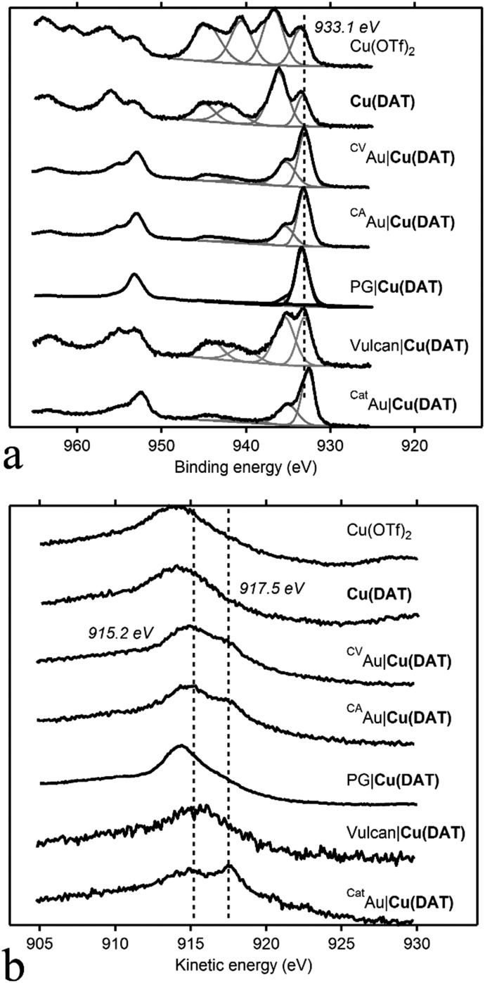
The Cu 2p3/2 region of the XPS spectrum of a Cu(OTf)2 reference sample contains two copper species with binding energies of BE (Cu 2p3/2) 933.5 eV and 936.8 eV that lie in the range typically found for CuII compounds such as CuO and Cu(OH)2 (Fig. 5).61 Moreover, pronounced shake-up satellite features typically observed for CuII species are present as well between 939 and 950 eV. Additionally, the Auger peak maximum in the Cu L3M4,5M4,5 spectrum with a kinetic energy (KE) of 914.0 eV corresponds to CuII species. In the C 1s spectrum, four additional peaks can be observed with a BE of 284.8, 286.2, 288.6 and 293.0 eV with the latter being the major species (Fig. S19, ESI†). This major species corresponds to the –CF3 group of triflate as it has a high BE and a ratio of 1 : 3 (C : F) with a fluorine species observed at a F 1s BE of 688.7 eV. The Cu 2p region of Cu(DAT) also contains the characteristic satellite features and two CuII species with BE of 936.2 eV and 933.2 eV. The Auger peak at KE = 914.5 eV is correspondingly indicative for the presence of CuII species. Four carbon species can be observed in the C 1s spectrum of Cu(DAT): two minor species with a BE of 284.8 and 286.5 eV and two major components at 288.6 and 292.6 eV. The latter species matches with the –CF3 group of Cu(OTf)2. In the N 1s region, a major species with a BE of 400.2 eV and a minor species with a BE of 401.6 eV were observed. The nitrogen to carbon ratio of these two nitrogen species with respect to the carbon species with a BE of 288.6 eV is 5 : 2 (Table 1 and Table S1, ESI†). This equals the expected 5 : 2 ratio of DAT; so the C 1s 288.6 eV and the two N 1s species are ascribed to DAT. Also, the ratio of the N 1s species with respect to the Cu 2p3/2 species is close to 5 : 1 (Table 1).
Fig. 5. XPS spectra (black lines) of the modified electrodes CVAu|Cu(DAT), CAAu|Cu(DAT), CatAu|Cu(DAT), PG|Cu(DAT) and the reference compounds Cu(DAT), Cu(OTf)2 and Vulcan|Cu(DAT). (a) Shows the Cu 2p region of the spectra and (b) shows the Cu L3M4,5M4,5 Auger spectra. In grey, the deconvolution of the Cu 2p3/2 region is depicted.
The XP spectra of the deposition on the modified electrodes CVAu|Cu(DAT) and CAAu|Cu(DAT) are almost identical. Thus, the formation of the deposition is not dependent on the preparation method being potentiostatic or potentiodynamic. Clearly, this deposition contains copper species as two CuII features in the Cu 2p3/2 region are observed: a major species with a BE of 933.1 eV and a minor species with shoulder at 935.3 eV. Additionally, the Auger peak has shifted to a KE of 915.2 eV. Both spectra are clearly not identical to Cu(DAT). Rather, the copper species might be associated with the presence of CuO and Cu(OH)2.61–64 The presence of CuII species is also confirmed by the existence of shake-up satellite features. For both electrodes, a noteworthy shift has taken place in the C 1s region. A major species with a BE of 287.1 eV and two minor species at 286.2 eV and 288.4 eV are present. The component at 284.8 eV can be ascribed to sp2 or sp3 carbon species but also adventitious carbon could contribute to the intensity of this peak. Both carbon species relating to triflate and to DAT are not observed further implying that Cu(DAT) is not present. Moreover, the N 1s species have shifted to a BE of 399.5 eV and 401.1 eV. None of the carbon species has a 5 : 2 ratio with the nitrogen species. Furthermore, the nitrogen to copper ratio has decreased and does not correspond to the expected 5 : 1 ratio anymore. These N 1s peaks still fall in the region previously ascribed to DAT,65,66 but are distinctively different from those observed in the Cu(DAT) reference and do not correspond to DAT anymore.
The modified electrode PG|Cu(DAT) has a different composition in the Cu 2p3/2 spectrum with respect to the Au|Cu(DAT) electrodes. Clearly, one major species is present with a BE of 933.3 eV. A minor species with a BE of 935.7 eV can be observed as well, yet less intense than in the Au supported samples. The binding energies fall still in the range expected for CuII species, and also the Cu L3M4,5M4,5 spectrum contains a relatively sharp peak at a kinetic energy of 914.3 eV suggesting the presence of CuII species. However, the typical shake-up satellite features supporting formation of a CuII state are absent in the case of PG|Cu(DAT). Apparently, the electrode material but also film thickness and different leaching rates have some influence on the exact identity of the copper deposition as the Cu 2p spectra differ for PG and Au. The N 1s spectrum contains one species at 399.5 eV at the same position as the major N 1s species found for all Au|Cu(DAT) electrodes. Clearly, none of the deposited samples has an electronic structure similar to molecular Cu(DAT).
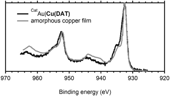
The spectra of the post-catalysis reference CatAu|Cu(DAT) are considerably different from CVAu|Cu(DAT) and CAAu|Cu(DAT) indicating a change in composition of the deposition. A major species at 932.6 eV and a minor 934.9 eV species (shoulder) are observed in the Cu 2p3/2 region. The low BE of the 932.6 eV species is indicative of a more reduced, electron rich species and correlate with CuI and/or Cu0 although exact differentiation cannot be done by XPS solely as CuII species are observed as well.61–63 Their presence is indicated by the 934.9 eV species and the minor satellite feature. This is further supported by the Cu L3M4,5M4,5 Auger spectrum that seems to consist of two components with KE of 914.0 eV and 917.5 eV, the latter being indicative of CuI species.61–63 The carbon composition has changed as at least four carbon signals are observed at 284.8, 286.3 eV, 287.2 eV and 288.5 eV. However, the intensities of these peaks have decreased with respect to CAAu|Cu(DAT) and CVAu|Cu(DAT) (Table S1, ESI†). No significant shift is observed for the species in the N 1s region. Notably, both the N : Cu and C : Cu ratios have decreased significantly as compared to CVAu|Cu(DAT) and CAAu|Cu(DAT) (Table 1 and Table S1, ESI†). Most important is the resemblance of CatAu|Cu(DAT) with the XPS spectrum of a previously reported electrodeposited amorphous Cu0 film (Fig. 6).64 This amorphous film was prepared galvanostatically in 0.1 M CuSO4 with 10 mM DAT as additive. The film contains considerably more CuII species than CatAu|Cu(DAT) based on the shake-up satellite features observed in both spectra (Fig. 6). Nonetheless, the activity of CatAu|Cu(DAT) is different from polycrystalline copper in the presence of DAT (Fig. S20–S22, ESI†).
Fig. 6. Superimposed XPS spectra of the Cu 2p region of CatAu|Cu(DAT) (solid black line) and of an amorphous electrodeposited copper film formed in the presence of DAT (dashed black line) as obtained by Hoang et al.64 The spectral data of the dashed line was reprinted and adapted with permission from ref. 64. Copyright 2017 American Chemical Society. The data was extracted using ScanIt.67.
3.5. Comparison to previous catalytic studies
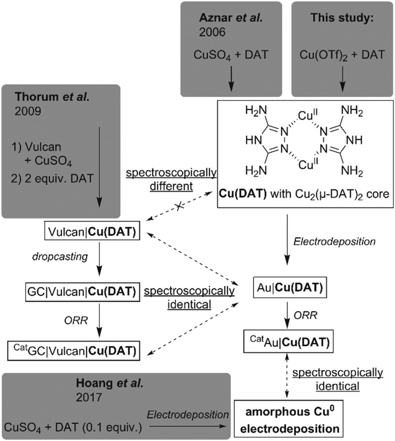
Previously, attempts to study the ORR activity of Cu(DAT) were made by sequential immobilization of CuSO4 and DAT on a carbon support (Vulcan).26 This strategy for catalytic studies was chosen as the use of CuSO4 leads to an insoluble analogue of Cu(DAT). Particularly, a suspension of this Vulcan|Cu(DAT) catalyst could be dropcasted on a GC electrode for electrochemical ORR measurements (GC|Vulcan|Cu(DAT)).26 In order to relate these results to ours (Scheme 1), Vulcan|Cu(DAT) was prepared according to the reported procedure (see ESI†).26 First of all, we essayed the nature of Vulcan|Cu(DAT) before any electrochemical survey or contact with buffers (Scheme 1). In previous studies no experiments to prove the presence of Cu(DAT) within Vulcan|Cu(DAT) have been undertaken.27–34
Scheme 1. Overview of samples prepared in this study and their spectroscopic similarity with previously reported Cu(DAT) related samples from literature.25,26,64 .
A powder EPR spectrum was recorded of Vulcan|Cu(DAT) (Fig. 2). The EPR spectrum of Vulcan|Cu(DAT) is very different compared to the EPR spectrum of Cu(DAT). Like Cu(DAT), the spectrum of Vulcan|Cu(DAT) does show the Ms = ±2 transitions indicative of closely spaced CuII centers. Nonetheless, the low g-factor of 2.00 observed in case of Vulcan|Cu(DAT) is very close to that of the free electron (g = 2.0023) rather than to values of 2.08–2.16 that are typical for triazole bridged copper sites, including Cu(DAT).25,39–42,68,69 This suggests that the electronic structure of Cu(DAT) and the copper sites in Vulcan|Cu(DAT) are largely different and that Vulcan|Cu(DAT) does not contain the Cu2(μ-DAT)2 core. Whereas the hyperfine coupling in Cu(DAT) is not resolved due to the close proximity of both copper sites,25 clear coupling patterns are visible in case of the Vulcan|Cu(DAT) sample. These latter splitting patterns are very difficult to simulate. Most likely, Vulcan|Cu(DAT) consists from a mixture of different species. Furthermore, XPS analysis shows a clear difference between Vulcan|Cu(DAT) and Cu(DAT) (Fig. 5 and Fig. S23, S24, ESI†). Instead, the Cu 2p3/2 and N 1s spectra of Vulcan|Cu(DAT) are identical to the spectra of the modified electrodes CAAu|Cu(DAT) and CVAu|Cu(DAT). It is remarkable that Vulcan|Cu(DAT) already resembles these Cu(DAT) deposits prior to any electrochemical treatment (Scheme 1).
Analogous to the original study of Thorum et al.,26 a GC electrode (GC|Vulcan|Cu(DAT)) was prepared for catalytic and post-catalytic studies by dropcasting Vulcan|Cu(DAT) and subsequently studying ORR in a pH 7 Britton–Robinson buffer and a pH 5 MES buffer (Fig. S25 and S26, ESI†). The activity of GC|Vulcan|Cu(DAT) is significantly higher under RRDE conditions than that of PG|Cu(DAT). The XPS spectra of the Cu 2p3/2 and N 1s regions of a post catalytic sample CatGC|Vulcan|Cu(DAT) were found to be identical to Vulcan|Cu(DAT) (Fig. S23 and S24, ESI†). In contrast to CVAu|Cu(DAT), the composition of the dropcasted CatGC|Vulcan|Cu(DAT) does not change upon performing ORR catalysis (Scheme 1).
Apparently, Vulcan plays a significant role in the activity of Vulcan|Cu(DAT) by stabilizing the structure of the active species, and preventing the formation of Cu0. This is in line with previous findings.26,27,31 Instead of forming a Cu2(μ-DAT)2 species, the DAT ligand may play a different role in the redox chemistry of GC|Vulcan|Cu(DAT), Au|Cu(DAT) and PG|Cu(DAT) as it is known to have a corrosion inhibitive effect on copper electrodes (Fig. S21, ESI†).70–72
4. Conclusions
We have obtained a water soluble Cu(DAT) complex containing the Cu2(μ-DAT)2 core identical to the previously reported crystal structure (Scheme 1).25 The Cu(DAT) complex in solution is very labile and its structure is extremely dependent on the precise reaction conditions. During electrocatalysis a deposition on the electrode surface is formed, which was found to be the active ORR catalyst. XPS studies showed that the structural integrity of the deposit has significantly changed with respect to the Cu(DAT) precursor and, on gold electrodes, is identical to Cu0 deposits in the presence of remnants of DAT as found by Hoang et al.64 (Scheme 1). XPS analysis has shown that the copper and nitrogen species found in Vulcan|Cu(DAT) are the same species found in the electrodeposition that is formed by Cu(DAT) on gold electrodes. Neither the deposition formed by Cu(DAT), nor Vulcan|Cu(DAT) contains the Cu2(μ-DAT)2 core (Scheme 1). Consequently, we have shown that the true active species is a copper deposition, which lacks a structural similarity with laccase. Most importantly, our findings signify that, in order to acquire more precise catalytically active laccase model systems for unraveling detailed structure–activity relationships, it is of vital importance to verify that the catalyst remains intact and does form a copper deposition instead.
Conflicts of interest
There are no conflicts of interest to declare.
Supplementary Material
Acknowledgments
Enrico Zurlo and Konstantin Kottrup of Leiden University are kindly acknowledged for their help with the EPR measurements. Longfei Wu of Eindhoven University of Technology is thanked for assistance in XPS measurements. Funding was provided by the European Research Council (ERC starting grant 637556 Cu4Energy to D. G. H. H.).
Footnotes
†Electronic supplementary information (ESI) available. See DOI: 10.1039/c8cp03419b
References
- Gasteiger H. A., Kocha S. S., Sompalli B., Wagner F. T. Appl. Catal., B. 2005;56:9–35. [Google Scholar]
- Gewirth A. A., Thorum M. S. Inorg. Chem. 2010;49:3557–3566. doi: 10.1021/ic9022486. [DOI] [PubMed] [Google Scholar]
- Nørskov J. K., Rossmeisl J., Logadottir A., Lindqvist L., Kitchin J. R., Bligaard T., Jónsson H. J. Phys. Chem. B. 2004;108:17886–17892. [Google Scholar]
- Gröger O., Gasteiger H. A., Suchsland J. P. J. Electrochem. Soc. 2015;162:A2605–A2622. [Google Scholar]
- Kongkanand A., Mathias M. F. J. Phys. Chem. Lett. 2016;7:1127–1137. doi: 10.1021/acs.jpclett.6b00216. [DOI] [PubMed] [Google Scholar]
- Bullen R. A., Arnot T. C., Lakeman J. B., Walsh F. C. Biosens. Bioelectron. 2006;21:2015–2045. doi: 10.1016/j.bios.2006.01.030. [DOI] [PubMed] [Google Scholar]
- Calabrese Barton S., Gallaway J., Atanassov P. Chem. Rev. 2004;104:4867–4886. doi: 10.1021/cr020719k. [DOI] [PubMed] [Google Scholar]
- Cracknell J. A., Vincent K. A., Armstrong F. A. Chem. Rev. 2008;108:2439–2461. doi: 10.1021/cr0680639. [DOI] [PubMed] [Google Scholar]
- Solomon E. I., Sundaram U. M., Machonkin T. E. Chem. Rev. 1996;96:2563–2606. doi: 10.1021/cr950046o. [DOI] [PubMed] [Google Scholar]
- Soukharev V., Mano N., Heller A. J. Am. Chem. Soc. 2004;126:8368–8369. doi: 10.1021/ja0475510. [DOI] [PubMed] [Google Scholar]
- Mano N., Soukharev V., Heller A. J. Phys. Chem. B. 2006;110:11180–11187. doi: 10.1021/jp055654e. [DOI] [PubMed] [Google Scholar]
- Blanford C. F., Heath R. S., Armstrong F. A. Chem. Commun. 2007:1710–1712. doi: 10.1039/b703114a. [DOI] [PubMed] [Google Scholar]
- Pita M., Mate D. M., Gonzalez-Perez D., Shleev S., Fernandez V. M., Alcalde M., De Lacey A. L. J. Am. Chem. Soc. 2014;136:5892–5895. doi: 10.1021/ja502044j. [DOI] [PubMed] [Google Scholar]
- Thorum M. S., Anderson C. A., Hatch J. J., Campbell A. S., Marshall N. M., Zimmerman S. C., Lu Y., Gewirth A. A. J. Phys. Chem. Lett. 2010;1:2251–2254. doi: 10.1021/jz100745s. [DOI] [PMC free article] [PubMed] [Google Scholar]
- Davis F., Higson S. P. J. Biosens. Bioelectron. 2007;22:1224–1235. doi: 10.1016/j.bios.2006.04.029. [DOI] [PubMed] [Google Scholar]
- Koper M. T. M., in Comprehensive Inorganic Chemistry II, ed. J. Reedijk and K. Poeppelmeier, Elsevier, Amsterdam, 2nd edn, 2013, vol. 8, pp. 459–474. [Google Scholar]
- Solomon E. I., Augustine A. J., Yoon J. Dalton Trans. 2008:3921–3932. doi: 10.1039/b800799c. [DOI] [PMC free article] [PubMed] [Google Scholar]
- Rulíšek L., Ryde U. Coord. Chem. Rev. 2013;257:445–458. [Google Scholar]
- Thorseth M. A., Tornow C. E., Tse E. C. M., Gewirth A. A. Coord. Chem. Rev. 2013;257:130–139. [Google Scholar]
- Mirica L. M., Ottenwaelder X., Stack T. D. P. Chem. Rev. 2004;104:1013–1046. doi: 10.1021/cr020632z. [DOI] [PubMed] [Google Scholar]
- Lewis E. A., Tolman W. B. Chem. Rev. 2004;104:1047–1076. doi: 10.1021/cr020633r. [DOI] [PubMed] [Google Scholar]
- Haack P., Limberg C. Angew. Chem., Int. Ed. 2014;53:4282–4293. doi: 10.1002/anie.201309505. [DOI] [PubMed] [Google Scholar]
- Serrano-Plana J., Garcia-Bosch I., Company A., Costas M. Acc. Chem. Res. 2015;48:2397–2406. doi: 10.1021/acs.accounts.5b00187. [DOI] [PubMed] [Google Scholar]
- Hong S., Lee Y.-M., Ray K., Nam W. Coord. Chem. Rev. 2017;334:25–42. [Google Scholar]
- Aznar E., Ferrer S., Borrás J., Lloret F., Liu-González M., Rodríguez-Prieto H., García-Granda S. Eur. J. Inorg. Chem. 2006:5115–5125. [Google Scholar]
- Thorum M. S., Yadav J., Gewirth A. A. Angew. Chem., Int. Ed. 2009;48:165–167. doi: 10.1002/anie.200803554. [DOI] [PubMed] [Google Scholar]
- Brushett F. R., Thorum M. S., Lioutas N. S., Naughton M. S., Tornow C., Jhong H.-R., Gewirth A. A., Kenis P. J. A. J. Am. Chem. Soc. 2010;132:12185–12187. doi: 10.1021/ja104767w. [DOI] [PubMed] [Google Scholar]
- Goenaga G. A., Belapure A., Zhang C., Papandrew A., Foister S., Zawodzinski T. ECS Trans. 2011;41:1193–1205. [Google Scholar]
- Kato M., Kimijima K. i., Shibata M., Notsu H., Ogino K., Inokuma K., Ohta N., Uehara H., Uemura Y., Oyaizu N., Ohba T., Takakusagi S., Asakura K., Yagi I. Phys. Chem. Chem. Phys. 2015;17:8638–8641. doi: 10.1039/c4cp05595k. [DOI] [PubMed] [Google Scholar]
- Kato M., Oyaizu N., Shimazu K., Yagi I. J. Phys. Chem. C. 2016;120:15814–15822. [Google Scholar]
- Thorum M. S., Hankett J. M., Gewirth A. A. J. Phys. Chem. Lett. 2011;2:295–298. [Google Scholar]
- Barile C. J., Tse E. C. M., Li Y., Sobyra T. B., Zimmerman S. C., Hosseini A., Gewirth A. A. Nat. Mater. 2014;13:619–623. doi: 10.1038/nmat3974. [DOI] [PubMed] [Google Scholar]
- Koshikawa H., Nakanishi S., Hashimoto K., Kamiya K. Electrochim. Acta. 2015;180:173–177. [Google Scholar]
- Tse E. C. M., Barile C. J., Kirchschlager N. A., Li Y., Gewargis J. P., Zimmerman S. C., Hosseini A., Gewirth A. A. Nat. Mater. 2016;15:754–759. doi: 10.1038/nmat4636. [DOI] [PubMed] [Google Scholar]
- Schouten K. J. P., Gallent E. P., Koper M. T. M. J. Electroanal. Chem. 2013;699:6–9. [Google Scholar]
- Abril P., del Río M. P., Tejel C., Verhoeven T. W. G. M., Niemantsverdriet J. W. H., Van der Ham C. J. M., Kottrup K. G., Hetterscheid D. G. H. ACS Catal. 2016;6:7872–7875. [Google Scholar]
- Koomen-Van Oudenniel W. M. E., De Graaff R. A. G., Haasnoot J. G., Prins R., Reedijk J. Inorg. Chem. 1989;28:1128–1133. [Google Scholar]
- van Koningsbruggen P. J., Haasnoot J. G., Kooijman H., Reedijk J., Spek A. L. Inorg. Chem. 1997;36:2487–2489. doi: 10.1021/ic9611002. [DOI] [PubMed] [Google Scholar]
- Slangen P. M., van Koningsbruggen P. J., Haasnoot J. G., Jansen J., Gorter S., Reedijk J., Kooijman H., Smeets W. J. J., Spek A. L. Inorg. Chim. Acta. 1993;212:289–301. [Google Scholar]
- Slangen P. M., van Koningsbruggen P. J., Goubitz K., Haasnoot J. G., Reedijk J. Inorg. Chem. 1994;33:1121–1126. [Google Scholar]
- Ferrer S., van Koningsbruggen P. J., Haasnoot J. G., Reedijk J., Kooijman H., Spek A. L., Lezama L., Arif A. M., Miller J. S. J. Chem. Soc., Dalton Trans. 1999:4269–4276. [Google Scholar]
- Prins R., Birker P. J. M. W. L., Haasnoot J. G., Verschoor G. C., Reedijk J. Inorg. Chem. 1985;24:4128–4133. [Google Scholar]
- Santangelo M. G., Medina-Molner A., Schweiger A., Mitrikas G., Spingler B. J. Biol. Inorg. Chem. 2007;12:767–775. doi: 10.1007/s00775-007-0230-1. [DOI] [PubMed] [Google Scholar]
- Nonoyama K., Ojima H., Nonoyama M. Inorg. Chim. Acta. 1984;84:13–18. [Google Scholar]
- Reedijk J., Knetsch D., Nieuwenhuijse B. Inorg. Chim. Acta. 1971;5:568–572. [Google Scholar]
- Antolini L., Fabretti A. C., Gatteschi D., Giusti A., Sessoli R. Inorg. Chem. 1991;30:4858–4860. [Google Scholar]
- Fabretti A. C. J. Crystallogr. Spectrosc. Res. 1992;22:523–526. [Google Scholar]
- Kröger G. F., Freiberg W. Z. Chem. 1965;5:381–382. [Google Scholar]
- Zhang T., Wang C., Liu S., Wang J.-L., Lin W. J. Am. Chem. Soc. 2014;136:273–281. doi: 10.1021/ja409267p. [DOI] [PubMed] [Google Scholar]
- Gomez V., Benet-Buchholz J., Martin E., Galan-Mascaros J. R. Eur. J. Inorg. Chem. 2014:3125–3132. [Google Scholar]
- Boland Y., Tinant B., Safin D. A., Marchand-Brynaert J., Clerac R., Garcia Y. CrystEngComm. 2012;14:8153–8155. [Google Scholar]
- Good N. E., Winget G. D., Winter W., Connolly T. N., Izawa S., Singh R. M. M. Biochemistry. 1966;5:467–477. doi: 10.1021/bi00866a011. [DOI] [PubMed] [Google Scholar]
- Kandegedara A., Rorabacher D. B. Anal. Chem. 1999;71:3140–3144. doi: 10.1021/ac9902594. [DOI] [PubMed] [Google Scholar]
- Mash H. E., Chin Y.-P., Sigg L., Hari R., Xue H. Anal. Chem. 2003;75:671–677. doi: 10.1021/ac0261101. [DOI] [PubMed] [Google Scholar]
- Schley N. D., Blakemore J. D., Subbaiyan N. K., Incarvito C. D., D’Souza F., Crabtree R. H., Brudvig G. W. J. Am. Chem. Soc. 2011;133:10473–10481. doi: 10.1021/ja2004522. [DOI] [PubMed] [Google Scholar]
- van der Ham C. J. M., Işık F., Verhoeven T. W. G. M., Niemantsverdriet J. W., Hetterscheid D. G. H. Catal. Today. 2017;290:33–38. [Google Scholar]
- Hetterscheid D. G. H. Chem. Commun. 2017;53:10622–10631. doi: 10.1039/c7cc04944g. [DOI] [PubMed] [Google Scholar]
- Sauerbrey G. Z. Phys. 1959;155:206–222. [Google Scholar]
- Paliteiro C., Hamnett A., Goodenough J. B. J. Electroanal. Chem. Interfacial Electrochem. 1987;233:147–159. [Google Scholar]
- Eul W., Moeller A. and Steiner N., Hydrogen Peroxide, Kirk-Othmer Encyclopedia of Chemical Technology, John Wiley & Sons, Inc., 2001, 10.1002/0471238961.0825041808051919.a01.pub2. [DOI] [Google Scholar]
- Biesinger M. C., Lau L. W. M., Gerson A. R., Smart R. S. C. Appl. Surf. Sci. 2010;257:887–898. [Google Scholar]
- Poulston S., Parlett P. M., Stone P., Bowker M. Surf. Interface Anal. 1996;24:811–820. [Google Scholar]
- NIST X-ray Photoelectron Spectroscopy Database. Version 4.1, National Institute of Standards and Technology, Gaithersburg, 2012, http://srdata.nist.gov/xps/.
- Hoang T. T. H., Ma S., Gold J. I., Kenis P. J. A., Gewirth A. A. ACS Catal. 2017;7:3313–3321. [Google Scholar]
- Finšgar M. Corros. Sci. 2013;77:350–359. [Google Scholar]
- Vasimalai N., John S. A. J. Mater. Chem. A. 2013;1:4475–4482. doi: 10.1039/c3tb20991a. [DOI] [PubMed] [Google Scholar]
- Balen J. v., ScanIt, 2.05, AmsterCHEM, 2017, https://www.amsterchem.com/scanit.html.
- Hathaway B. J., Billing D. E. Coord. Chem. Rev. 1970;5:143–207. [Google Scholar]
- Solomon E. I., Heppner D. E., Johnston E. M., Ginsbach J. W., Cirera J., Qayyum M., Kieber-Emmons M. T., Kjaergaard C. H., Hadt R. G., Tian L. Chem. Rev. 2014;114:3659–3853. doi: 10.1021/cr400327t. [DOI] [PMC free article] [PubMed] [Google Scholar]
- Guo L., Dong W., Zhang S. RSC Adv. 2014;4:41956–41967. [Google Scholar]
- El Ibrahimi B., Soumoue A., Jmiai A., Bourzi H., Oukhrib R., El Mouaden K., El Issami S., Bazzi L. J. Mol. Struct. 2016;1125:93–102. [Google Scholar]
- Zarrouk A., Hammouti B., Al-Deyab S. S., Salghi R., Zarrok H., Jama C., Bentiss F. Int. J. Electrochem. Sci. 2012;7:5997–6011. [Google Scholar]
Associated Data
This section collects any data citations, data availability statements, or supplementary materials included in this article.


