

The phase state of a spin-triplet Josephson junction containing three ferromagnetic layers is magnetically controlled.
Abstract
It is now well established that a Josephson junction made from conventional spin-singlet superconductors containing ferromagnetic layers can carry spin-triplet supercurrent under certain conditions. The first experimental signature of that fact is the propagation of such supercurrent over long distances through strong ferromagnetic materials. Surprisingly, one of the most salient predictions of the theory has yet to be verified experimentally—namely, that a Josephson junction containing three magnetic layers with coplanar magnetizations should exhibit a ground-state phase shift of either zero or π depending on the relative orientations of those magnetizations. We demonstrate this property using Josephson junctions containing three different types of magnetic layers, chosen so that the magnetization of one layer can be switched by 180° without disturbing the other two. Phase-sensitive detection is accomplished using a superconducting quantum interference device, or SQUID. Such a phase-controllable junction could be used as the memory element in a fully superconducting computer.
INTRODUCTION
The prediction in 2001 that spin-triplet supercurrent can be generated from conventional spin-singlet superconductors (1, 2) caused considerable excitement in the field. Spin-triplet superconductors occur very rarely in nature, but the theory suggested a completely new route to the generation of spin-triplet electron pairs. The mechanism of the transformation from spin-singlet to spin-triplet pairs is now well established conceptually (3). Spin-singlet pairs traversing a ferromagnetic material undergo a phase shift between the up-down and down-up parts of the spin-singlet wave function, which generates the ms = 0 component of the spin-triplet state, where ms is the spin projection along the magnetization axis. If the electrons then enter another ferromagnetic layer whose magnetization axis is rotated, then ms = ±1 triplet components are generated in the rotated basis. Before 2001, it was thought that any proximity effects or supercurrents in superconducting-ferromagnetic hybrid systems would be very short-ranged due to the large energy and momentum shift between the majority and minority spin bands of a ferromagnetic material (4, 5). Spin-triplet pairs with projection ms = ±1 along the magnetization axis (often called “equal-spin triplets” in the literature) overcome that problem because the two electrons propagate in the same spin band; hence, they perceive the ferromagnetic material as though it were a normal metal. As a result, supercurrent carried by spin-triplet pairs can propagate long distances through ferromagnetic materials.
Experimental verification of the theory appeared initially in 2006 (6, 7); then, in 2010, several groups produced overwhelming evidence for long-range supercurrents in Josephson junctions containing strong ferromagnetic materials—a telltale signature of spin-triplet electron pairs (8–11). Our own approach to this field uses the Josephson junction design first suggested by Houzet and Buzdin in 2007 (12), in which the junction contains three ferromagnetic (F) materials with mutually perpendicular magnetizations between adjacent F layers. We showed recently that the spin-triplet supercurrent can be turned on and off by rotating the magnetization of one of those layers so that it is either perpendicular or parallel to the magnetization of the adjacent layer (13).
The theory of spin-triplet junctions also makes predictions about the current-phase relation of spin-triplet junctions. In a standard superconductor-insulator-superconductor (SIS) Josephson junction, the current-phase relation is Is = Ic sin(ϕ), where Ic is the critical current (the maximum value of supercurrent that can flow through the junction without producing any voltage drop) and ϕ is the difference in phase between the superconducting condensates on either side of the junction. Junctions obeying the standard current-phase relation have a stable ground-state phase difference of ϕ = 0 in the absence of supercurrent; hence, these junctions are sometimes called “0-junctions.” Josephson junctions containing ferromagnetic materials may have the sign of the supercurrent reversed, that is, Is = −Ic sin(ϕ) = Ic sin(ϕ + π) (4, 14). Such junctions are called “π-junctions” because the stable state in the absence of supercurrent corresponds to ϕ = π. According to theory, spin-triplet Josephson junctions containing three ferromagnetic layers can also be 0-junctions or π-junctions, depending on the relative magnetization directions of those three layers (2, 12, 15, 16). Confirmation of that theoretical prediction is the goal of this paper.
The physical mechanism underlying the zero-current phase state in spin-triplet junctions differs from that in spin-singlet junctions. In the latter, the π-junction behavior arises solely from the phase shift acquired between the up-down and down-up parts of the spin-singlet wave function as the electron pair traverses the ferromagnetic layer, as discussed in the first paragraph (4, 5, 14). In spin-triplet junctions, as long as the two outer ferromagnetic layers are thin enough so as not to generate a spin-singlet π phase shift by themselves, the choice of whether the junction will be a 0-junction or a π-junction depends on the direction of magnetization rotation going from the first to the second ferromagnetic layer compared to the direction of magnetization rotation going from the second to the third. If those two directions are the same, then the junction will be a 0-junction, whereas if the rotations are in opposite directions, then the junction will be a π-junction (2, 12, 15, 16).
RESULTS
We measure the junction phase by constructing a superconducting quantum interference device (SQUID) containing two Josephson junctions fabricated simultaneously (see Fig. 1). The two junctions have different shapes—one elliptical and the other an elongated hexagon—so that the magnetization direction of the free layer in the elliptical junction can be switched without altering any of the magnetic layers in the other junction. The layer structure of the junctions is S/N/F′/N/F/N/F″/N/S, where S = superconductor, N = normal metal, and F′, F, and F″ are ferromagnetic materials. The two requirements for this experiment are that the magnetizations of any two adjacent layers be orthogonal to maximize generation of the ms = ±1 triplet components, and that the magnetization direction of one layer—either the F′ or F″ layer—be free to rotate by 180° without disturbing the other two. We accomplish that by using magnetic materials with in-plane magnetization for F′ and F″ and out-of-plane magnetization for F. For F″, we choose Ni because it is very “hard”—that is, it requires a high field to switch its magnetization direction. For F′, we choose permalloy (Py), a NiFe alloy, because it is very “soft” and switches its magnetization direction with an applied field of only a few millitesla. For F, we use a [Pd/Co]n multilayer (n repeats of a Pd/Co bilayer) with strong perpendicular magnetic arisotropy (PMA). This choice guarantees that the magnetization of F remains perpendicular to the magnetizations of F′ and F″ under all measurement conditions. To reduce the possibly deleterious effect of stray magnetic fields emanating from domain walls in F, we use two back-to-back [Pd/Co]n multilayers whose magnetizations are coupled antiparallel to each other by a thin Ru spacer, to form a synthetic antiferromagnet (SAF).
Fig. 1. Spin-triplet Josephson junction structure and SQUID loop design.
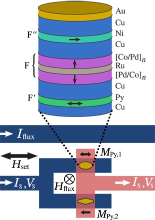
Top: Schematic cross section of the central layers in our Josephson junctions (not to scale). The central F layer is composed of two [Pd (0.9 nm)/Co (0.3 nm)]n multilayers with perpendicular magnetic anisotropy (PMA), separated by a Ru (0.95 nm) spacer to form a synthetic antiferromagnet (SAF). The outer F′ and F″ layers have in-plane magnetization; we used Permalloy (Py) for F′ and Ni for F″. One junction has an elliptical cross section (aspect ratio, 2.0) to make its F′ layer switch at a low field, while the other is an elongated hexagon (aspect ratio 3.0); both have an area of 0.5 μm2. Bottom: The two junctions are arranged into a SQUID loop. An external field Hset is used to control the magnetization directions of the F′ and F″ layers inside the junctions; all measurements are performed with Hset = 0. The current Iflux passing through a nearby superconducting line creates an out-of-plane field Hflux, which couples magnetic flux Φ into the SQUID loop. The Py magnetizations are shown as black arrows labeled MPy,1 and MPy,2.
The first step in the experiment is to verify that the Josephson junctions described above actually carry spin-triplet supercurrent. We verified that in a recent work (17) by comparing the supercurrent amplitude in junctions with and without the outer F′ and F″ layers. Junctions without those layers are expected to carry only spin-singlet and short-range ms = 0 spin-triplet supercurrent, whereas junctions with those layers should carry long-range spin-triplet supercurrent. We found that the magnitude of the supercurrent in the latter set of samples decreased less rapidly as a function of the number n of bilayers in the [Pd/Co]n multilayers, confirming the long-range nature of the supercurrent in the central multilayer. Here, we focus on junctions with n = 2 or 3 on each side of the SAF, corresponding to a total of four or six [Pd/Co] bilayers.
The next step is to perform the phase-sensitive experiment depicted in the bottom of Fig. 1. Before starting any measurements, a large in-plane field μ0Hset = −150 mT is applied in the negative field direction—that is, to the left in Fig. 1—and then removed. That field initializes the magnetization directions of the Ni and Py layers in both junctions (17). The PMA SAF is stiff enough that its magnetization hardly rotates in the initialization field, and in any case, it returns to its perpendicular magnetic state after Hset returns to zero. We then remove any trapped flux in the Nb layers by momentarily lifting the measurement dip stick so that the sample is above the liquid helium level and the Nb layers enter the normal state. After lowering the dip stick, we measure the critical current Ic of the SQUID as a function of the current Iflux passing through a nearby superconducting line. In an idealized Josephson junction, Ic is defined as the largest supercurrent that can pass through the junction without causing any voltage drop to appear. Junctions with small critical current exhibit some voltage drop even when I < Ic if the Josephson energy EJ = ℏIc/2e is not sufficiently large compared to the temperature and environmental noise. Figure 2B shows typical I-V curves along with fits to a theory that takes those into account, as explained in Materials and Methods. The current Iflux produces a very small out-of-plane field, which induces magnetic flux through the SQUID loop. The Ic(Iflux) data exhibit oscillations with a period of about 1.5 mA, corresponding to one flux quantum Φ0 = h/2e through the SQUID loop. We then apply a small in-plane “set field,” μ0Hset = 0.4 mT, in the positive direction—to the right in Fig. 1. After returning the field to zero, we measure the full SQUID oscillation data Ic(Iflux) again. We repeat this sequence while increasing the magnitude of μ0Hset in steps of 0.4 mT. The results are shown for SQUID sample 2A-4 in Fig. 2A as a 3D plot of Ic versus Iflux and Hset. The 3D plot shows that the Ic(Iflux) oscillation curve does not change for values of μ0Hset up to 2.0 mT. At μ0Hset = 2.4 mT, the SQUID oscillation curve suddenly shifts by almost exactly ½Φ0, indicating that one of the junctions in the SQUID has acquired a π phase shift relative to the initial state. According to the theory of spin-triplet Josephson junctions (2, 12, 15, 16), that phase shift occurs when the magnetizations of the F′ and F″ layers switch from being parallel to antiparallel, which is consistent with the Py F′ layer in one of the junctions (probably the elliptical one) reversing its magnetization direction. We then repeat the whole procedure with negative values of μ0Hset to return the system to its initial state. As shown in Fig. 2A, the transition back to the initial state occurs at μ0Hset = −2.8 mT. The flux shift of ½Φ0 is instantly apparent in the raw data without any further analysis.
Fig. 2. SQUID data.
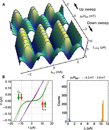
(A) Three-dimensional (3D) plot of a minor loop for SQUID 2A-4: critical current versus Iflux and Hset. The critical current plotted, Ic,Avg, is the average of the critical currents in the positive and negative current directions, Ic,Avg = (Ic+ + |Ic−|)/2 [see (B)]. Before any measurements are made, μ0Hset is set to −150 mT to initialize the magnetizations of the Ni and Py layers in both junctions. With Hset = 0, Ic is measured as a function of Iflux and exhibits oscillations with a period of about 1.5 mA, corresponding to the flux quantum, Φ0 = h/2e. Then, Hset is stepped in the positive direction (labeled “Up sweep” in the figure), returning to zero after each step for sample measurement. The SQUID oscillations exhibit a horizontal shift of ½Φ0 at μ0Hset = +2.4 mT, indicating that one of the Josephson junctions has changed its ground-state phase by π. The SQUID remains in that state as Hset is increased further, but increasing Hset too far causes the second junction to switch; the data shown here stop before that occurs. Next, Hset is stepped in the negative direction (labeled “Down sweep”) until μ0Hset = −2.8 mT, where the SQUID switches back to the original state. (B) Current-voltage characteristics obtained at Iflux = −0.2 mA for the two magnetic states: in the π state with maximum Ic (green symbols) and in the initial 0 state with minimum Ic (purple symbols). The solid green and purple lines are fits to the current-voltage relation (I-V) curves with the Ivanchenko-Zil’bermann (IZ) function (see Materials and Methods), while the red and blue dashed lines are fits to the simpler square-root function used to obtain the data in (A) and (C). The latter fits give values of Ic about 20% lower than the former, as shown by the Ic+ and Ic− labels. (C) Repeated switching between the P and the AP states at Iflux = −0.2 mA. The histogram shows the measured values of Icavg in the two states while the magnetic field was toggled between +2.8 and −3.2 mT 1000 times.
The fact that the switching field required to return the Py magnetization to its initial direction is slightly larger in magnitude than the field required to switch it antiparallel to the Ni magnetization could be explained in principle by the magnetostatic interaction between the Ni and Py layers. In practice, however, both switching fields vary somewhat from sample to sample due to uncontrolled sources of anisotropy, for example, disorder or magnetostriction.
To test the reproducibility and robustness of the results, we have switched device 2A-4 between its two magnetic states 1000 times, while keeping Iflux fixed at −0.2 mA to maximize the difference between the values of Ic in the two states. Figure 2C shows a histogram of the resulting Ic values. The narrow distributions of Ic values in the two magnetic states show that the behavior is highly reproducible over multiple switches. We have carried out similar measurements on eight different SQUIDs—four with n = 2 and four with n = 3. We obtained results similar to those shown in Fig. 2 from seven of the eight SQUIDs; only one SQUID with n = 3 exhibited poor magnetic behavior with the phase appearing to move continuously rather than switching abruptly. The SQUIDs with n = 3 have lower values of the critical current, as expected from our previous work (17). However, their phase behavior, with the exception of the one poor sample, is just as robust as that of the n = 2 SQUIDs.
One can extract quantitative estimates of the individual junction critical currents and the SQUID phase shift by fitting the Ic(Iflux) data for each magnetic state to standard SQUID theory (18), as shown in Fig. 3 for the same device 2A-4. In principle, these fits provide estimates of the four SQUID parameters—the critical currents of the two Josephson junctions, Ic1 and Ic2, and the inductances of the two arms of the SQUID, L1 and L2—and an overall horizontal shift of the central peak from zero flux, which we call Φshift. Our SQUIDs are in the low-inductance limit defined by βL ≡ (Ic1 + Ic2)(L1 + L2)/Φ0 << 1; in that limit, it is difficult to extract accurate inductance estimates from the fits. Nevertheless, we have good estimates of the inductances from numerical simulations of the SQUID structure using the FastHenry software, as well as from previous work with similar SQUIDs containing Josephson junctions with only two magnetic layers and much larger critical currents (19). Since fluctuations in the fitted values of L1 and L2 tend to correlate with fluctuations in the fitted values of Ic1 and Ic2, we obtained our most consistent fitting results by fixing the values of the two inductances to L1 = L2 = 4.5 pH, and letting only Ic1, Ic2, and Φshift vary in the fitting procedure. The results of fitting all seven data sets, in both magnetic states, are shown in Table 1. The most important results are in the last column, which shows the change in Φshift between the two magnetic states for each of the seven SQUIDs, in units of the flux quantum, Φ0. All flux shifts are very close to ½ Φ0, which corresponds to a phase shift of π for one of the two junctions in the SQUID. That observation is the primary result of this work.
Fig. 3. High-resolution SQUID data and fits.
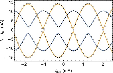
Plot of Ic+ and Ic− versus Iflux for SQUID 2A-4. The solid circles correspond to the initialized magnetic state, while the stars correspond to the second state after one junction has switched. The values of Ic+ and Ic− shown in this figure were obtained by fitting the IZ function to the raw I-V curves as shown in Fig. 2B. The solid lines (blue for the initial state and yellow for the second state) are least-squares fits to the data of standard SQUID theory [see (18) and Materials and Methods]. Values for the critical currents of the two Josephson junctions obtained from the fits are given in Table 1.
Table 1. Fit parameters for the seven spin-triplet SQUID samples measured.
The first two characters in the sample name, for example, “2A,” refer to the chip, while the final number refers to the specific device on the chip. (Each chip contains four SQUIDs.) The value 2n is the total number of [Pd/Co] bilayers in the central F layer. The SQUID oscillation curves were fit to standard SQUID theory, as shown in Fig. 3 for device 2A-4, while keeping the total inductance fixed to the nominal value of 9 pH. The last column of the table shows that the flux shifts of the SQUID oscillation curves between the two magnetic states are very close to ½Φ0, which corresponds to a phase shift of π for one of the two junctions in the SQUID. The fits also provide approximate values of the critical currents in the two junctions, Ic1 and Ic2. (The uncertainties in the values of Ic1 and Ic2 derived from the fits appear to be too small, as the value of Ic2 for the nonswitching junction appears to change between the two magnetic states. We believe that this is a generic feature of fits to SQUID data for SQUIDs in the low-inductance limit, βL << 1.) The data for all samples except 2A-4 can be found in the Supplementary Materials.
| SQUID name | 2n | State | Ic1 (μA) | Ic2 (μA) | ΔΦshift/Φ0 |
| 2A-1 | 4 | 1 | 6.65 ± 0.08 | 4.20 ± 0.08 | 0.491 ± 0.005 |
| 2 | 6.90 ± 0.12 | 4.18 ± 0.12 | |||
| 2A-2 | 4 | 1 | 4.09 ± 0.14 | 4.02 ± 0.14 | 0.542 ± 0.004 |
| 2 | 5.66 ± 0.10 | 5.61 ± 0.10 | |||
| 2A-3 | 4 | 1 | 4.53 ± 0.12 | 4.56 ± 0.12 | 0.480 ± 0.004 |
| 2 | 6.88 ± 0.07 | 4.67 ± 0.07 | |||
| 2A-4 | 4 | 1 | 4.56 ± 0.04 | 6.16 ± 0.04 | 0.509 ± 0.003 |
| 2 | 7.30 ± 0.15 | 7.08 ± 0.15 | |||
| 3A-3 | 6 | 1 | 0.80 ± 0.30 | 0.79 ± 0.30 | 0.519 ± 0.010 |
| 2 | 1.99 ± 0.02 | 1.34 ± 0.02 | |||
| 4A-1 | 6 | 1 | 0.60 ± 0.33 | 3.16 ± 0.33 | 0.618 ± 0.005 |
| 2 | 1.45 ± 0.03 | 3.87 ± 0.03 | |||
| 4A-2 | 6 | 1 | 1.32 ± 0.04 | 2.41 ± 0.04 | 0.493 ± 0.004 |
| 2 | 3.01 ± 0.01 | 1.61 ± 0.01 |
DISCUSSION
There are three aspects of the data in Table 1 that are not ideal. First, the observed values of ΔΦshift between the two magnetic states deviate from ½Φ0 for all seven measured SQUIDs, typically by a few percent. (The deviation is largest for sample 4A-1, which is a sample with n = 3, hence with a very small critical current.) Small deviations from π may be due to changes in the SQUID flux coming from the switching Py layer, as we observed in previous work on junctions containing only two magnetic layers (19). That contribution could be removed by designing a SQUID with higher symmetry, such that the magnetizations of the ferromagnetic layers in the junctions do not inject any flux into the SQUID. Another possibility, however, is that the change in phase of the switching junction is not exactly π. It has been predicted theoretically that spin-triplet junctions containing three magnetic layers with non-coplanar magnetizations can exhibit a ground-state phase shift of any value, not just 0 or π (16, 20–22). These junctions are called “ϕ0-junctions” in the literature, as they have a current-phase relation of the form Is = Icsin(ϕ + ϕ0). In our sample geometry, where the magnetization of the middle F layer points perpendicular to the sample plane, the three magnetizations remain coplanar if the Py magnetization is either parallel or antiparallel to the Ni magnetization, but they become non-coplanar if the Py magnetization deviates from those orientations while remaining in-plane. Note, however, that even if the Py and Ni magnetizations are not exactly parallel or antiparallel, the change in the junction phase that occurs when the Py magnetization switches would still be π if the Py magnetization rotates by exactly 180°. Our experiment was not designed to create a ϕ0-junction; choosing elongated shapes for both junctions was meant to ensure that the Ni and Py magnetizations would align preferentially along the long axes of the elliptical and hexagonal junctions. Nevertheless, we cannot rule out the possibility that the deviations from 0.5 in the last column of Table 1 are due to a slight ϕ0-junction behavior. In the future, we plan to fabricate one of the two junctions with a circular shape to explore ϕ0-junction physics explicitly.
A second departure from ideality in Table 1 is the fact that the critical currents of both junctions appear to change between magnetic states. Given the robust results for ΔΦshift, we are confident that only one of the two Josephson junctions in the SQUID changes its magnetic state at the transitions visible in Fig. 2. A close look at the data in the table shows that Ic1 changes much more than Ic2 in most samples. We believe that the changes in Ic2 shown in the table indicate limitations of the data-fitting procedure for SQUIDs with very small critical currents.
Last, the theory of spin-triplet Josephson junctions predicts that the amplitude of the critical current should be the same in the two magnetic states if the free layer switches its magnetization direction by exactly 180° (2, 12, 15, 16). Our samples exhibited that critical current symmetry only once, during the first measurements of SQUID 2A-1, and even that sample violated the symmetry during subsequent measurement runs. To explain that discrepancy, we initially hypothesized that our junctions might be carrying a small amount of spin-singlet supercurrent in addition to the spin-triplet supercurrent, so that the two interfere constructively in one state and destructively in the other state. However, that hypothesis fails for the samples with n = 3, where we know that the amplitude of the spin-singlet supercurrent is negligible compared to the spin-triplet supercurrent (17). A more likely explanation is that the Fraunhofer pattern of the elliptical switching junction is shifted more in the initial state where the Ni and Py magnetizations are parallel compared to the second state where those magnetizations are antiparallel. As a result, the measured critical current of that junction is less than the maximum value one would find at the peak of its Fraunhofer pattern. A close look at the single-junction Fraunhofer data shown in fig. 7 of (17) shows that the values of Ic measured in zero applied field are 20 to 30% larger in the antiparallel state (after the junction switches) than in the parallel state. That is consistent with the data in the table for all our SQUID samples.
A Josephson junction whose ground-state phase difference can be controllably switched between 0 and π has potential uses in high-speed superconducting single-flux quantum circuits or in quantum computing circuits (23–28). Our primary interest is to make a superconducting memory (19, 29). For the latter application, we envisage a SQUID loop containing two conventional SIS Josephson junctions (where I = insulator) and one ferromagnetic junction that acts as a passive phase shifter. The shift of the Ic(ϕ) curve of the SQUID is easily detected by applying appropriate current bias and flux to the memory cell. The advantage of such a design is that only the SIS junctions switch into the voltage state during readout of the memory (29). By switching the SIS junctions, a much larger signal is generated since ferromagnetic junctions typically have an IcR value of only a few microvolts or less.
From an applications perspective, there are easier ways to make a phase-controllable Josephson junction: We showed recently that a “spin-valve” Josephson junction containing only two magnetic layers of appropriate thicknesses could also exhibit controllable 0-π switching (19). In those devices, the physical mechanism of the 0-π phase shift is different; it relies on the accurate tuning of the thicknesses of the two magnetic layers so that the total phase shift acquired by an electron pair traversing the sample is closer to an even or odd multiple of π when the two magnetizations are parallel or antiparallel. In the spin-triplet devices presented here, the 0-π switching is caused by spin rotations rather than phase accumulation, so the behavior is less sensitive to the exact thicknesses of the F′ and F″ layers. We believe that fact partially explains the high degree of consistency we observed in the seven samples measured. Another possible advantage of the design presented here is that the central PMA SAF shields the free Py layer from stray magnetic fields emanating from the Ni-fixed layer. A disadvantage of our devices is that their critical currents are very small. In the future, we hope to enhance the critical currents by optimizing the materials in the stack.
MATERIALS AND METHODS
Experimental design
The experiment was designed with the intent of making the main conclusions immediately apparent in the raw data, without further data analysis. The SQUIDs used in this study were designed to be symmetric, in contrast to the SQUIDs used in our previous study of spin-valve Josephson junctions (19). Asymmetric SQUIDs with large critical current and large inductance (βL > 1) exhibit asymmetric ratchet-shaped SQUID oscillations in plots of Ic(Φ), and the peaks in Ic+ and Ic− are shifted in opposite directions along the Φ axis. Even if the SQUID is geometrically symmetric, shifts in the Ic+ and Ic− peak positions will arise if the critical currents of the two junctions are not equal. Given the small values of Ic in the spin-triplet samples in this work, those shifts are very small, as shown by the data in Fig. 3. Hence, the global flux shift of Φ0/2 that occurs when the magnetic state changes is immediately apparent in the data.
Choice of magnetic materials
The ferromagnetic materials were chosen based on previous work in our group reported in (13, 19) and references therein. Among strong ferromagnetic materials, we and others have found that Ni supports the largest supercurrents. In addition, thin Ni layers have a very high coercive field, so it serves as a good “fixed magnetic layer” in the stack. Two disadvantages of Ni are that it requires a very large initialization field to magnetize it completely, and that for our junction sizes, the Ni nanomagnets are almost certainly not single domain. For that reason, after the initial magnetization at high field, we always keep the applied field low enough to avoid disturbing the domain structure of the Ni. For the free layer, Py (Ni80Fe20) is the best choice we have found to date that provides clean switching between magnetic states at relatively low fields, as seen in Fig. 2. The one disadvantage of Py is that it does not support as much supercurrent as Ni. Typical switching characteristics of elliptically shaped Py and Ni nanomagnets can be seen in Fig. 2 of (30), which shows critical current data of single Josephson junctions (not SQUIDs) containing only two magnetic layers. In the current work, only one of the two junctions in each SQUID is shaped as an ellipse; the other junction is a hexagon with high aspect ratio. The Py layers in the hex junctions generally do not switch as cleanly as those in the elliptical junctions, but, fortunately, they switch at higher field. By keeping Hset sufficiently small, we were able to avoid switching the hex junctions during the experiments. The [Co/Pd] multilayers that form the SAF with PMA were used for the first time in the work reported in (17).
Sample fabrication
The sample fabrication procedure was described in detail in (17); here, we summarize the main steps. The bottom leads consist of a multilayer of the form [Nb(25)/Al(2.4)]3/Nb(20)/Au(2)/Cu(2)/Py(1.25)/Cu(4)/[Pd(0.9)/Co(0.3)]n/Ru(0.95)/[Co(0.3)/Pd(0.9)]n/Cu(4)/Ni(1.6)/Cu(7)/Au(2), where all thicknesses are in nanometers. The [Nb/Al] multilayer base was used in place of pure Nb because it has a smoother surface and leads to better magnetic switching behavior of the free Py layer [see (17) and references therein]. The [Pd/Co] multilayers have strong PMA, and the Ru(0.95) spacer couples the two PMA multilayers into a SAF. The Cu(4) spacers decouple adjacent magnetic layers, while the bottom Cu(2) spacer facilitates growth of face-centered cubic Py on top of body-centered cubic Nb. The multilayer was sputtered in a seven-gun high-vacuum sputtering system with a base pressure below 2 × 10⁻⁸ torr, with the substrate maintained at a temperature between −30° and −15°C. Because the multilayer contains nine different materials while the system contains only seven guns, the sputtering was interrupted after the first Au(2) layer, and the system was opened to replace the Nb and Al guns with the Co and Pd guns. During the gun exchange, the samples were enclosed in a plastic bag filled with flowing N2 gas to limit contamination. After the system was closed, it was pumped down overnight, and the Au(2) was ion-milled away before deposition of the remainder of the stack. The entire bottom multilayer described above was deposited through a photolithographic stencil (with an S1813 photoresist) to define the dimensions of the bottom leads using the lift-off process.
Following lift-off, e-beam lithography and Ar ion milling were used to define the junction areas, using the negative e-beam resist ma-N2401 as the ion mill protective mask. Immediately following ion milling, 50 nm of SiOx was deposited by thermal evaporation for electrical isolation. Then, the samples were ion-milled at glancing angle from two directions to break through the SiOx sidewalls around the junctions. Subsequent lift-off of the ma-N2401 was performed in warm Remover PG with the aid of gentle wiping with a cotton swab. Following lift-off, the sample was subjected to an O2 plasma “descum” process to ensure complete removal of the ma-N2401 from the tops of the junctions. Finally, the top lead pattern was defined with another photolithography step. The protective Au(2) layer was ion-milled away immediately before sputtering the top Nb(150)/Au(10) electrode. Sample fabrication was completed by lift-off of the photoresist.
Sample measurement and fits to I-V data
For measurement, NbTi wires were attached to the Nb/Au pads using pressed indium. The samples were immersed in liquid He. Current was provided by a battery-powered low-noise current source, while the voltage was measured using a SQUID-based self-balancing potentiometer circuit with a voltage noise of a few pV/√Hz (31).
I-V characteristics are typical of overdamped Josephson junctions (32), but the I-V curves exhibit substantial rounding for currents less than the critical current, Ic, due to environmental and instrumental noise, as shown in Fig. 2B. Rounded I-V curves are well described by the Ivanchenko-Zil’berman (IZ) function (33–35), while less-precise estimates of Ic can be obtained by fitting the data to the standard form for overdamped Josephson junctions: V = R × Real{(I2 − Ic2)½}. Because fitting I-V curves with the IZ function is computationally time-consuming, we carried out the initial data analysis shown in Fig. 2 using the simpler square-root fits and then used the IZ function to fit the data sets that will be subjected to further quantitative analysis, that is, the data shown in Fig. 3. When fitting single-junction or SQUID data with the IZ function, we have found that the effective noise temperature of our apparatus is typically about 40 K—considerably higher than the actual sample temperature [see Fig. 4 and Table 1 in (35)]. Nevertheless, the IZ function fits the data very well, and the IZ fits give consistent values of critical current, which vary systematically with applied flux, as shown in Fig. 3. When fitting data with the IZ function, we fit the positive and negative current sweep data simultaneously, with a common value for the normal-state resistance, R, but with separate values for the positive and negative critical currents, Ic+ and Ic−. That is required in principle because the values of Ic+ and Ic− are generally different for a SQUID unless the SQUID is completely symmetric, that is, the critical currents of the two junctions are identical and the inductances of the two arms are identical. In our SQUIDs, the inductances are identical to a very high degree, but the junction critical currents are not, especially when one of the junctions has switched into the antiparallel magnetic state while the other is still in the initial parallel magnetic state. Because our SQUIDs have low values of βL, however, we find in every case that Ic+ and Ic− are nearly equal, as shown in Fig. 3.
Supplementary Material
Acknowledgments
We thank S. Bergeret, A. Herr, D. Miller, O. Namaan, N. Rizzo, and M. Schneider for helpful discussions; J. Willard for performing FastHenry simulations; and B. Bi for help with fabrication using the Keck Microfabrication Facility. Funding: This research was supported by the Office of the Director of National Intelligence (ODNI), Intelligence Advanced Research Projects Activity (IARPA), via U.S. Army Research Office contract no.W911NF-14-C-0115. The views and conclusions contained herein are those of the authors and should not be interpreted as necessarily representing the official policies or endorsements, either expressed or implied, of the ODNI, IARPA, or the U.S. Government. Author contributions: The project was conceived by N.O.B. with extensive input from and preliminary work by B.M.N., E.C.G., and W.P.P. J.A.G. fabricated and measured all the samples and analyzed the data. V.A. made substantial improvements to the data acquisition software. A.B.G., J.A.G., and N.O.B. carried out variable-temperature measurements on the samples. W.P.P. and R.L. designed, built, and maintained the deposition and measurement apparatus. N.O.B. and J.A.G. wrote the paper with input from all authors. Competing interests: N.O.B. is a co-inventor of U.S. Patent 9,013,916 B2, “Josephson magnetic memory cell system,” which could use junctions of the type discussed in this work. All other authors declare that they have no competing interests. Data and materials availability: All data needed to evaluate the conclusions in the paper are present in the paper and/or the Supplementary Materials. Additional data related to this paper may be requested from the authors.
SUPPLEMENTARY MATERIALS
Supplementary material for this article is available at http://advances.sciencemag.org/cgi/content/full/4/7/eaat9457/DC1
Additional Low-Temperature Measurements
Data from Additional Samples
Fig. S1. Low-temperature measurements of sample 2A-1 with additional filtering.
Fig. S2. Data from sample 2A-1.
Fig. S3. Data from sample 2A-2.
Fig. S4. Data from sample 2A-3.
Fig. S5. Data from sample 3A-3.
Fig. S6. Data from sample 4A-1.
Fig. S7. Data from sample 4A-2.
REFERENCES AND NOTES
- 1.Bergeret F. S., Volkov A. F., Efetov K. B., Josephson current in superconductor-ferromagnet structures with a nonhomogeneous magnetization. Phys. Rev. B 64, 134506 (2001). [DOI] [PubMed] [Google Scholar]
- 2.Volkov A. F., Bergeret F. S., Efetov K. B., Odd triplet superconductivity in superconductor-ferromagnet multilayered structures. Phys. Rev. Lett. 90, 117006 (2003). [DOI] [PubMed] [Google Scholar]
- 3.Eschrig M., Spin-polarized supercurrents for spintronics. Phys. Today 64, 43–49 (2011). [DOI] [PubMed] [Google Scholar]
- 4.Buzdin A. I., Bulaevskii L. N., Panyukov S. V., Critical-current oscillations as a function of the exchange field and thickness of the ferromagnetic metal (F) in a S-F-S Josephson junction. Pis’ma Zh. Eksp. Teor. Fiz. 35, 147–148 (1982). [Google Scholar]
- 5.Demler E. A., Arnold G. B., Beasley M. R., Superconducting proximity effects in magnetic metals. Phys. Rev. B 55, 15174–15182 (1997). [Google Scholar]
- 6.Keizer R. S., Goennenwein S. T. B., Klapwijk T. M., Miao G., Xiao G., Gupta A., A spin triplet supercurrent through the half-metallic ferromagnet CrO2. Nature 439, 825–827 (2006). [DOI] [PubMed] [Google Scholar]
- 7.Sosnin I., Cho H., Petrashov V. T., Volkov A. F., Superconducting phase coherent electron transport in proximity conical ferromagnets. Phys. Rev. Lett. 96, 157002 (2006). [DOI] [PubMed] [Google Scholar]
- 8.Khaire T. S., Khasawneh M. A., Pratt W. P. Jr, Birge N. O., Observation of spin-triplet superconductivity in Co-based Josephson junctions. Phys. Rev. Lett. 104, 137002 (2010). [DOI] [PubMed] [Google Scholar]
- 9.Robinson J. W. A., Witt J. D. S., Blamire M. G., Controlled injection of spin-triplet supercurrents into a strong ferromagnet. Science 329, 59–61 (2010). [DOI] [PubMed] [Google Scholar]
- 10.Sprungmann D., Westerholt K., Zabel H., Weides M., Kohlstedt H., Evidence for triplet superconductivity in Josephson junctions with barriers of the ferromagnetic Heusler alloy Cu2MnAl. Phys. Rev. B 82, 060505 (2010). [Google Scholar]
- 11.Anwar M. S., Czeschka F., Hesselberth M., Porcu M., Aarts J., Long-range supercurrents through half-metallic ferromagnetic CrO2. Phys. Rev. B 82, 100501 (2010). [Google Scholar]
- 12.Houzet M., Buzdin A. I., Long range triplet Josephson effect through a ferromagnetic trilayer. Phys. Rev. B 76, 060504 (2007). [Google Scholar]
- 13.Martinez W. M., Pratt W. P. Jr, Birge N. O., Amplitude control of the spin-triplet supercurrent in S/F/S Josephson junctions. Phys. Rev. Lett. 116, 077001 (2016). [DOI] [PubMed] [Google Scholar]
- 14.Buzdin A. I., Proximity effects in superconductor-ferromagnet heterostructures. Rev. Mod. Phys. 77, 935–976 (2005). [Google Scholar]
- 15.Volkov A. F., Efetov K. B., Odd spin-triplet superconductivity in a multilayered superconductor-ferromagnet Josephson junction. Phys. Rev. B 81, 144522 (2010). [DOI] [PubMed] [Google Scholar]
- 16.Trifunovic L., Radovic Z., Long-range spin-triplet proximity effect in Josephson junctions with multilayered ferromagnets. Phys. Rev. B 82, 020505 (2010). [Google Scholar]
- 17.Glick J. A., Edwards S., Korucu D., Aguilar V., Niedzielski B. M., Loloee R., Pratt W. P. Jr, Birge N. O., Kotula P. G., Missert N., Spin-triplet supercurrent in Josephson junctions containing a synthetic antiferromagnet with perpendicular magnetic anisotropy. Phys. Rev. B 96, 224515 (2017). [Google Scholar]
- 18.B. Chesca, R. Kleiner, D. Koelle, SQUID theory, in The SQUID Handbook, J. Clarke, A. I. Braginski, Eds. (Wiley, 2004), vol. 1. [Google Scholar]
- 19.Gingrich E. C., Niedzielski B. M., Glick J. A., Wang Y., Miller D. L., Loloee R., Pratt W. P. Jr, Birge N. O., Controllable 0–π Josephson junctions containing a ferromagnetic spin valve. Nat. Phys. 12, 564–567 (2016). [Google Scholar]
- 20.Margaris I., Paltoglou V., Flytzanis N., Zero phase difference supercurrent in ferromagnetic Josephson junctions. J. Phys. Condens. Matter 22, 445701 (2010). [DOI] [PubMed] [Google Scholar]
- 21.Liu J.-F., Chan K. S., Anomalous Josephson current through a ferromagnetic trilayer junction. Phys. Rev. B 82, 184533 (2010). [Google Scholar]
- 22.Silaev M. A., Tokatly I. V., Bergeret F. S., Anomalous current in diffusive ferromagnetic Josephson junctions. Phys. Rev. B 95, 184508 (2017). [Google Scholar]
- 23.Terzioğlu E., Beasley M. R., Complementary Josephson junction devices and circuits: A possible new approach to superconducting electronics. IEEE Trans. Appl. Supercond. 8, 48–53 (1998). [Google Scholar]
- 24.Ioffe L. B., Geshkenbein V. B., Feigel’man M. V., Fauchère A. L., Blatter G., Environmentally decoupled sds-wave Josephson junctions for quantum computing. Nature 398, 679–681 (1999). [Google Scholar]
- 25.Ustinov A. V., Kaplunenko V. K., Rapid single-flux quantum logic using π shifters. J. Appl. Phys. 94, 5405–5407 (2003). [Google Scholar]
- 26.Yamashita T., Tanikawa K., Takahashi S., Maekawa S., Superconducting π qubit with a ferromagnetic Josephson junction. Phys. Rev. Lett. 95, 097001 (2005). [DOI] [PubMed] [Google Scholar]
- 27.Khabipov M. I., Balashov D. V., Maibaum F., Zorin A. B., Oboznov V. A., Bolginov V. V., Rossolenko A. N., Ryazanov V. V., A single flux quantum circuit with a ferromagnet-based Josephson π-junction. Supercon. Sci. Technol. 23, 045032 (2010). [Google Scholar]
- 28.Feofanov A. K., Oboznov V. A., Bol’Ginov V. V., Lisenfeld J., Poletto S., Ryazanov V. V., Rossolenko A. N., Khabipov M., Balashov D., Zorin A. B., Dmitriev P. N., Koshelets V. P., Ustinov A. V., Implementation of superconductor/ferromagnet/ superconductor π-shifters in superconducting digital and quantum circuits. Nature Phys. 6, 593–597 (2010). [Google Scholar]
- 29.Dayton I. M. , Sage T., Gingrich E. C. , Loving M. G., Ambrose T. F., Siwak N. P., Keebaugh S., Kirby C., Miller D. L., Herr A. Y., Herr Q. P., Naaman O., Experimental demonstration of a Josephson magnetic memory cell with a programmable π-junction. IEEE Magn. Lett. 9, 3301905 (2018). [Google Scholar]
- 30.Niedzielski B. M., Bertus T. J., Glick J. A., Loloee R., Pratt W. P. Jr, Birge N. O., Spin-valve Josephson junctions for cryogenic memory. Phys. Rev. B 97, 024517 (2018). [Google Scholar]
- 31.Edmunds D. L., Pratt W. P. Jr, Rowlands J. A., 0.1 ppm four-terminal resistance bridge for use with a dilution refrigerator. Rev. Sci. Instrum. 51, 1516–1522 (1980). [Google Scholar]
- 32.A. Barone, G. Paterno, Physics and Applications of the Josephson Effect (Wiley, 1982). [Google Scholar]
- 33.Ivanchenko Y. M., Zil’berman L. A., The Josephson effect in small tunnel contacts. Zh. Eksp. Teor. Fiz. 55, 2395–2402 (1968). [Google Scholar]
- 34.Ambegaokar V., Halperin B. I., Voltage due to thermal noise in the dc Josephson effect. Phys. Rev. Lett. 22, 1364–1366 (1969). [Google Scholar]
- 35.Glick J. A., Khasawneh M. A., Niedzielski B. M., Loloee R., Pratt W. P. Jr, Birge N. O., Gingrich E. C., Kotula P. G., Missert N., Critical current oscillations of elliptical Josephson junctions with single-domain ferromagnetic layers. J. Appl. Phys. 122, 133906 (2017). [Google Scholar]
Associated Data
This section collects any data citations, data availability statements, or supplementary materials included in this article.
Supplementary Materials
Supplementary material for this article is available at http://advances.sciencemag.org/cgi/content/full/4/7/eaat9457/DC1
Additional Low-Temperature Measurements
Data from Additional Samples
Fig. S1. Low-temperature measurements of sample 2A-1 with additional filtering.
Fig. S2. Data from sample 2A-1.
Fig. S3. Data from sample 2A-2.
Fig. S4. Data from sample 2A-3.
Fig. S5. Data from sample 3A-3.
Fig. S6. Data from sample 4A-1.
Fig. S7. Data from sample 4A-2.