

Abstract
Active tactile exploration behaviour is constrained to a large extent by the morphological and biomechanical properties of the animal's somatosensory system. In the model organism Carausius morosus, the main tactile sensory organs are long, thin, seemingly delicate, but very robust antennae. Previous studies have shown that these antennae are compliant under contact, yet stiff enough to maintain a straight shape during active exploration. Overcritical damping of the flagellum, on the other hand, allows for a rapid return to the straight shape after release of contact. Which roles do the morphological and biomechanical adaptations of the flagellum play in determining these special mechanical properties? To investigate this question, we used a combination of biomechanical experiments and numerical modelling. A set of four finite-element (FE) model variants was derived to investigate the effect of the distinct geometrical and material properties of the flagellum on its static (bending) and dynamic (damping) characteristics. The results of our numerical simulations show that the tapered shape of the flagellum had the strongest influence on its static biomechanical behaviour. The annulated structure and thickness gradient affected the deformability of the flagellum to a lesser degree. The inner endocuticle layer of the flagellum was confirmed to be essential for explaining the strongly damped return behaviour of the antenna. By highlighting the significance of two out of the four main structural features of the insect flagellum, our study provides a basis for mechanical design of biomimetic touch sensors tuned to become maximally flexible while quickly resuming a straight shape after contact.
Keywords: active exploration, flagellum, cuticle, damping, biomimetics
1. Introduction
Among all the remarkable sensory organs of insects, the antenna might be considered as one of the most complex structures. Apart from olfaction, gustation and thermoreception, insect antennae are the key sensory organs for active exploration of the near-range environment [1,2]. The behavioural function of the antenna as a mechanosensory organ is governed by the mechanical properties of its distal part: the flagellum. For active tactile exploration, two characteristics of the flagellum are of particular importance: its compliant bending behaviour during contact events and the maintenance (or control) of a stable shape throughout the non-contact episodes. High compliance is a prerequisite for robustness and resilience in the face of unpredictable contact times. A stable shape greatly simplifies reliable tactile localization of contact sites, because it reduces the need for monitoring sensor shape. Here, we investigate how different structural features of the insect antenna affect the trade-off between compliance during contact and maintenance of shape during active searching.
A relatively well-studied biomechanical model of the insect antenna is the long and slender antenna of the Indian stick insect Carausius morosus. The stick insect antenna consists of three functional segments, of which only the two most proximal—the scapus and pedicellus—can be moved actively (figure 1a). Both antennal joints can be considered hinge joints with 1 d.f. only [3]. The two joint axes are non-orthogonal and slanted against both the sagittal and horizontal body planes [4]. This morphological structure has been suggested to improve the positioning accuracy of the antenna [3]. Whenever a stick insect walks or climbs, it actively moves its antennae, thus raising the likelihood of the antenna touching objects in the immediate environment (electronic supplementary material, video S1).
Figure 1.
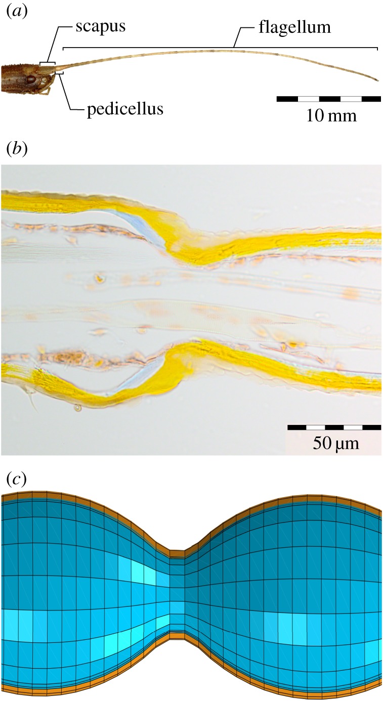
General morphology of the antenna of the stick insect C. morosus. (a) Head and antenna. The antenna consists of three morphological parts: scapus, pedicellus and flagellum. (b) Longitudinal section of the medial region of the flagellum showing the annulated and tapered structure of a filiform antenna. Each annulus is connected to the next segment via a thin cuticular bridge consisting of both exo- and endocuticle (Azan-stained paraffin section, 10 µm thickness; exocuticle: orange, endocuticle: blue). (c) Schematic longitudinal section of the model used in this study showing two adjacent annuli from the middle part of the model. Brown and blue colours represent exo- and endocuticle, respectively.
Almost all contacts between the antenna and external objects occur on the third segment of the antenna: the flagellum (figure 1a). The flagellum of C. morosus is filiform (long and thin, thread-like). In adult animals, it has a length of approximately 25–35 mm with a length-to-diameter ratio of approximately 100 : 1. The bi-layered cuticle has a stiff outer exocuticle layer, which allows the flagellum to maintain shape during active movement, and a compliant inner endocuticle layer that has been suggested to dampen unwanted oscillations [5]. Owing to the long and thin structure, the flagellum can strongly bend during contact events (e.g. [6]) (electronic supplementary material, video S1). This is similar to the cockroach flagellum, which undergoes significant bending during tactually induced climbing [7] or wall-following behaviour [8]. Although it is clear that structural features such as the flagellum diameter or cuticle thickness must affect the bending properties of a flagellum, these properties vary along the length of the flagellum, both gradually (as in a tapering diameter) and locally, e.g. through annulation. Annulation refers to the structural ‘subdivision’ of the flagellum into several flagellomeres that are often called annuli (figure 1b). These annuli are not connected via true joints, but rather via thin cuticular ‘necks’. Each annulus carries a number of sensilla, putatively allowing the insect to determine the location, taste and texture of the contacted surface during tactile exploration (reviewed by [1,2]).
To date, at least four structural features of arthropod antennae are known to affect the bending properties of a flagellum. These are (i) the tapering from a relatively thick base to a much thinner tip (crayfish [9]; lobster [10]; stick insect [5]; cockroach [8]), (ii) the change in cuticle thickness along the length of the flagellum (stick insect [5]), (iii) the presence of a compliant endocuticle (a feature of insect cuticle, in general, [11]), and (iv) the annulation of the surface structure (crickets [12]).
Despite the large diversity of antennal morphology among insects, several of these four structural features are very common, if not omnipresent. Therefore, it is not possible to explore the functional significance of these properties through a comparative approach, for example, after careful selection of different insect species with distinct differences in antennal structure. Instead, this study combines experimental measurements with numerical simulations of a finite-element (FE) model of the stick insect flagellum. To this end, we use one ‘full model’ as a reference, along with a set of four deficient models where only one of the properties was discarded: (i) no annuli, (ii) no tapering of the diameter, (iii) no longitudinal gradient of cuticle thickness, and (iv) no endocuticle.
2. Material and methods
2.1. Static and dynamic mechanical deflection of the antenna
Adult stick insects of the species C. morosus (de Sinéty 1901) were carefully immobilized on a platform using minutien pins (N = 6). To prevent active movement of the antenna, the scapus–pedicellus joint was fixed using dental cement (Protemp, ESPE). The distal end of the pedicellus–flagellum junction was used as a reference point for the measurements.
For the static deflection measurements, a minutien pin was pinned at predetermined deflection points marked on the platform. For each deflection point, the antenna of the immobilized insect was carefully moved across the pin and allowed to mechanically relax until it reached a stable shape without touching the platform. The only point of contact was the pin. Pictures of the antenna shape were taken using a digital camera (Nikon CoolPix 995). The shape of the antenna was manually tracked using a custom-written Matlab script that stored an arbitrary number of points from the base of the flagellum to the tip. Between trials, the antenna was carefully moved back to the initial resting position to prevent any effects of plastic deformation. The order of the deflection points was randomized. Measurements were performed with deflection in the dorsal direction. This kind of deflection naturally occurs whenever a downward movement of the antenna leads to a contact. This is very common during active tactile exploration in stick insects.
The curvature of the antenna was calculated from the manually labelled coordinates along the length of the flagellum, using a custom-written program (Borland Delphi 7). If not stated otherwise, the data shown for the flagellum shape are the arithmetic average for six antennae. First, a fixed number of evenly spaced nodes along the flagellum were obtained through interpolation of the manually labelled points. Then, the local curvature at the nth node, 1/rn, where r is the radius of curvature in millimetres, was determined by calculating the angle, φn, between the line segments adjacent to that node. Assuming a circle with radius rn running through a subsequent triplet of nodes n − 1 to n + 1, φn is equal to the angle between the lines connecting adjacent nodes and the centre of the circle (because of the even spacing of the nodes). Thus, the local radius of curvature is
| 2.1 |
where l is the distance between nodes.
Data for the dynamic deflection were taken from experiments published in our previous study, where the respective methods were described in detail [5]. In these experiments, the antennae of the immobilized insect were manually deflected and allowed to swing back into their resting position. The passive return movement of the antenna was recorded optically by a position-sensing photodiode. The study by Dirks and Dürr has shown that the dynamic movements of the stick insect antennae, in particular those of dried antennae, are very stereotypical with only very small variation among samples.
The static and dynamic experiments were repeated on the antennae 3–4 days after removal. The results were used to test the influence of desiccation on the mechanical behaviour of the antenna in both loading scenarios.
2.2. Numerical modelling
2.2.1. Finite-element modelling of the flagellum
Based on the data from previously published morphological studies [5,13], we developed five three-dimensional (3D) FE models of the flagellum of the stick insect. The models, created using the ABAQUS FE software package (v.6.14; Simulia, Providence, RI, USA), were designed to have different geometrical and material characteristics (figure 2).
Figure 2.

Summary of flagellum models used in this study. Top: Schematic of the antenna. Each model variant is depicted by schematic longitudinal sections through a basal, medial and distal region of the flagellum. The reference model is the most comprehensive model. It comprises all four structural and material properties (exocuticle: orange, endocuticle: blue). In all other model variants, one of the properties was removed. Compared with the reference model, the model ‘no annuli’ lacks the annulated structure. In the model ‘no tapering’, the annulated flagellum has a constant diameter. Model ‘no thickness gradient’ has a constant cuticle thickness along the length of the flagellum. Model ‘no endocuticle’ has the same geometry as the reference model; however, the endocuticle is replaced by exocuticle, thus removing the bi-layered structure.
The ‘reference model’ was the most comprehensive model in our study. It contained all four structural features under investigation and all four were set to be similar to a real flagellum of an adult stick insect (figure 2). It had a total length of 27 mm. The outer diameter gradually tapered from 351 µm at the base, to 187 µm in the middle section to 170 µm at the tip. The reference model formed a hollow structure with two cuticular layers, comprising a stiff outer exocuticle and a soft inner endocuticle. The thickness of the exocuticle layer was 17.2 µm at the base of the flagellum; it remained constant throughout the middle part, and then linearly decreased towards the tip to 8.3 µm. The endocuticle was modelled to have a thickness which continuously decreased from 17 µm at the base to 4.2 µm in the middle and further to 1.6 µm at the tip. The reference model contained 36 annuli with semi-elliptical shapes (figure 1c). The values used here are the mean values obtained from measurements on N = 6 insects. Detailed information on the variations of the measurements can be found in our previous study [5].
The model ‘no annuli’ lacked the annulated structure, while maintaining the tapering of the reference model (figure 2). Comparison of the results from this model and the reference model allowed us to estimate the influence of local changes in diameter and cuticle thickness on the mechanical behaviour of the flagellum.
In order to study the effect of the decreasing diameter and decreasing thickness, two additional flagellum models similar to the reference model were designed: model ‘no tapering’ had a constant diameter of the annuli, whereas model ‘no thickness gradient’ had constant cuticle thickness along the entire length of the flagellum (figure 2). The diameter of model ‘no tapering’ and the cuticle thickness of model ‘no thickness gradient’ were chosen to be equal to those in the middle section of the reference model.
The effect of the bi-layered cuticle structure, i.e. the presence of an endocuticle layer, on both the static and dynamic behaviour of the insect flagellum was examined by setting the mechanical properties of the endocuticle layer to those of the exocuticle layer (model ‘no endocuticle’). As a result, the geometric features of the inner layer remained the same as in the reference model, but the material properties changed.
The above-mentioned models allowed us to investigate the effects selectively caused by annulation, tapering diameter, variable cuticle thickness and the presence of endocuticle on the mechanical behaviour of the flagellum of the stick insect C. morosus. Table 1 lists the geometric characteristics of the developed models.
Table 1.
Parameters of the flagellum models at the base, in the middle and at the tip.
| base of the model |
middle of the model |
tip of the model |
||||||||||
|---|---|---|---|---|---|---|---|---|---|---|---|---|
| model no. | max. diameter (µm) | exocuticle thickness (µm) | endocuticle thickness (µm) | max. diameter (µm) | exocuticle thickness (µm) | endocuticle thickness (µm) | max. diameter (µm) | exocuticle thickness (µm) | endocuticle thickness (µm) | number of elements for the dynamic analysis | number of elements for the static analysis | time constant (ms) |
| reference | 351 | 17.2 | 17.0 | 187 | 17.2 | 4.2 | 170 | 8.3 | 1.6 | 25 920 | 45 033 | 72.3 |
| no annuli | 351 | 17.2 | 17.0 | 187 | 17.2 | 4.2 | 170 | 8.3 | 1.6 | 18 850 | 32 815 | 58.4 |
| no tapering | 187 | 17.2 | 17.0 | 187 | 17.2 | 4.2 | 187 | 8.3 | 1.6 | 26 010 | 45 188 | 80.0 |
| no gradient | 351 | 17.2 | 4.2 | 187 | 17.2 | 4.2 | 170 | 17.2 | 4.2 | 26 305 | 45 810 | 142.5 |
| no endocuticle | 351 | 34.2 | — | 187 | 21.4 | — | 170 | 9.9 | — | 25 920 | — | — |
General-purpose eight-node shell elements with reduced integration (S8R) were employed to mesh the developed models. While the use of the reduced-integration scheme in these elements decreased the computational time, their second-order formulation improved the accuracy of the results.
A mesh convergence analysis was performed to eliminate the influence of the element size on numerical predictions. The number of elements used for each model is given in table 1.
2.2.2. Material properties
A previous histological study showed that the flagellar cuticle of the Indian stick insect C. morosus is bi-layered, with a sclerotized outer exocuticle lined by a non-sclerotized endocuticle [5]. With an assumed elastic modulus of 9.6 GPa, the exocuticle generally has a considerably higher stiffness than the endocuticle, the elastic modulus of which was set to 2 MPa [14]. These values correspond to the elastic modulus of the strongly sclerotized cuticle of the gula of the beetle Pachnoda marginata [15] and that of the highly hydrated cuticle of the intersegmental membrane of the locust Schistocerca gregaria (Jensen and Weis-Fogh), respectively. It has also been demonstrated that the exocuticle has a density of about 1200 kg m−3 [16]. Considering the strongly hydrated nature of the endocuticle, a density of 1000 kg m−3 was assigned to this layer [16,17]. Poisson's ratio of both the exo- and endocuticle layers was assumed to be 0.49 [18]. Based on the data of the damping experiments of Dirks & Dürr [5] on the fresh and desiccated antenna samples, the damping ratios of the exo- and endocuticle layers were set to 0.02 and 1, respectively. The material properties mentioned earlier have already been used by the authors to simulate the mechanical behaviour of several insect cuticles [19–24] as well as the damping behaviour of the cuticle of wing veins of the dragonfly Sympetrum vulgatum [25].
2.2.3. Loading and boundary conditions
The reference model was first used to simulate the static bending tests on the flagellum. The results of this simulation were employed to verify the validity of the modelling method and the solving procedure. Based on these validation results, we were able to investigate the mechanical behaviour of the flagellum, especially its deformation mechanism under both small and large deflections. For this purpose, the virtual model was fixed at the base, and then different deflections were applied to the model at three deflection points: 5 mm, 15 mm and 22.5 mm distally from the fixation site.
The simulation of the dynamic behaviour of the flagellum was performed by applying an initial deflection and then modelling the dynamic return movements of the deflected virtual flagellum. To this end, the models followed the experimental set-up of Dirks & Dürr [5] and were fixed at 10 mm from the base with a deflection applied at their distal end. In each case, the deflections of the models were captured at a position 5 mm distally from the fixation site.
In our simulations, we did not take the influence of gravity into account because the deformation of the flagellum due to gravitation is negligible.
2.2.4. Geometric nonlinearity
Based on behavioural and experimental observations, the stick insect flagellum can experience and withstand large deflections during active exploration (electronic supplementary material, video S1). These deflections are caused by the relative movement of the annuli with respect to each other. Although they are elastic, such large deflections can result in a nonlinear response of the structure to the applied loads. Numerical simulation of this nonlinear behaviour is only possible by considering the influence of geometric nonlinearities. Recently, it has been demonstrated that the application of such a nonlinear analysis yields more accurate predictions of the mechanical behaviour of insect cuticle [14,19,26,27].
The conventional linear structural analysis is based on the assumption of infinitesimal deflections. The concept of geometric nonlinearity, by contrast, considers the effect of geometric changes on the structural response of a mechanical system. The use of nonlinear analysis in a FE simulation allows the distortion of the elements experiencing high stresses and, therefore, results in more accurate solutions. In this study, we performed a nonlinear analysis, which implies a nonlinear relationship between strains and displacements. The strain-displacement equation can be generally expressed in the following form:
| 2.2 |
where ɛ is the strain vector, u is the displacement field and [B] represents the strain-displacement matrix. Consideration of geometric nonlinearity results in a nonlinear strain-displacement matrix [28]. In such a case, due to the large displacements, the deformation of a model becomes nonlinear, but it still remains in the elastic range.
2.2.5. Damping model
The application of Newton's law for a linear elastic multi-degree-of-freedom system with linear viscous damping yields the following equation of motion [29]:
| 2.3 |
where [m], [c] and [k] are the mass, damping and stiffness matrices, respectively. x(t) is the displacement vector as a function of time.  and
and  denote the first- and second-order derivatives with respect to time.
Taking into account the complexity of the damping phenomenon in a biological structure like the stick insect flagellum, it is difficult to identify all causes of energy dissipation. Here, therefore, we used an equivalent viscous damping representation to introduce the damping mechanism to our flagellum models. Rayleigh damping is a promising method for this purpose and has conventionally been used for simplified modelling of the overall damping behaviour of engineering structures [30–32]. In a recent study, we used the Rayleigh damping method to simulate the dynamic response of the cuticle of wing veins of the dragonfly S. vulgatum [25]. The method was able to precisely quantify the dynamic behaviour of the veins. Based on the Rayleigh damping method, the damping matrix is assumed to be proportional to a linear combination of the mass and stiffness matrices [33],
| 2.4 |
where α and β are Rayleigh damping coefficients with units of s−1 and s, respectively.
The flagellum can be simplified as a single-degree-of-freedom system. For such a vibrating system with the mass, stiffness and damping constant of m, k and c, respectively, we can write [29]
| 2.5 |
| 2.6 |
In the above equations, ζ and ωn are the damping ratio and natural frequency, respectively. Substituting equations (2.5) and (2.6) into equation (2.3), and using the orthogonality condition of the mode shapes, the following equation can be derived for the ith vibration mode of the system:
| 2.7 |
Considering ζ1 and ζm as the damping ratios associated with the 1st and mth modes with frequencies of ω1 and ωm, equation (2.7) can be expressed in the following matrix form:
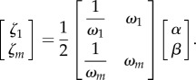 |
2.8 |
Hence, α and β can be calculated by solving these two equations. The assumption of the same damping ratio (ζ = ζ1 = ζm) for both vibration modes results in
| 2.9 |
and
| 2.10 |
The calculated values of the Rayleigh damping coefficients are used to define the damping behaviour of the flagellum models. Table S1 in the electronic supplementary material lists the damping coefficients calculated for each individual model.
2.2.6. Quality of the model
To compare the quality of the different models, we used the magnitude of the maximum curvature and its site along the flagellum. First, we normalized the length of six antennae and the numerical models. We then calculated the shape of an average antenna for each deflection amplitude and deflection point (arithmetic mean, N = 6 different antennae). As an approximation for the error, we then calculated the Euclidian distance between the experimental data points and the corresponding data points from the numerical models (table 2). To account for variation, we calculated the median Euclidian distance for each flagellum region (base, middle, tip) over all deflection points, as well as a median Euclidian distance over all flagellum regions combined (‘total’ error) for both the antenna and each model. Larger Euclidian distances corresponded to larger deviations between the models and the reference.
Table 2.
Median of Euclidian distances sum (errors) between the experimental data and the respective models for three different deflection points (base: 5 mm; middle: 15 mm; tip: 22.5 mm) along the flagellum and over all deflection points combined (total). The comprehensive reference model shows consistently low errors irrespective of the deflection point in comparison with the other models with limited features. The ‘no annuli’ model shows the overall smallest median error in comparison with the other models. The ‘no tapering’ model shows the overall largest total sum of errors, illustrating the importance of the tapering of the flagellum.
| base | middle | tip | total | |
|---|---|---|---|---|
| reference | 3.39 | 9.66 | 4.62 | 4.02 |
| no annuli | 4.59 | 29.58 | 2.65 | 2.83 |
| no tapering | 9.86 | 30.86 | 6.47 | 8.18 |
| no gradient | 3.23 | 22.81 | 6.69 | 5.14 |
3. Results
3.1. Deformation of the biological flagellum
Our experimental results show that, depending on the amplitude and point of the applied deflection, the antenna of C. morosus exhibited characteristic deformed shapes (figure 3a showing a representative shape from N = 6 insects). The static deformation behaviour of the tested stick insect antenna was very stereotypical for each deflection direction. Only a small variation was observed between the results obtained from the tests on different flagellum specimens.
Figure 3.

Representative examples for different shapes of the flagellum of C. morosus for static dorsal deflections at three different distances from the pedicellus–flagellum junction (deflection point: 5, 15 and 22.5 mm, as depicted by different line types, one antenna). At each deflection point, deflection amplitudes ranged between 1.25 and 7.5 mm relative to resting posture.
The non-deflected antenna showed a typical slight ventral curvature in the distal region of the flagellum (approx. 22.5 mm from the pedicellus–flagellum joint). As figure 3 shows, a deflection in the middle section of the flagellum generally leads to a smaller local deformation than more distal deflections. The largest local deformation always occurred proximally to the deflection point. Distally to the contact point, the flagellum did not show deformations notably different from those occurring at rest.
To analyse the deformation of the flagellum in more detail, we calculated the curvature along the flagellum (inverse radius of curvature, 1/r) for each combination of deflection parameters (figure 4). For a given, fixed deflection point along the flagellum figure 4a shows that larger deflection amplitudes cause higher curvature, with very little change in the location of the maximum curvature along the flagellum. However, by contrast, different deflection points lead to different sites of maximum curvature (figure 4b). Therefore, the overall curvature profile, i.e. static shape, of the flagellum appears to be unique for any contact point in the dorsoventral plane.
Figure 4.

Use of curvature to quantify the deformation behaviour of the flagellum. (a) Representative example for the curvature along the flagellum for dorsal deflection at the same deflection point (22.5 mm), but different deflection amplitudes. The site of maximum curvature remains almost unaffected by the amplitude of deflection. (b) Curvature for dorsal deflection with the same deflection amplitude (3.75 mm), but for different distances from fixation. The sites of maximum curvature shift distally with increasing distal deflection.
In summary, the flagellum showed stronger deformations with increasing deflection amplitudes. The site of the strongest deformation was correlated with the deflection amplitude and was always located proximally from the deflection point. The largest deformations were observed in the distal or proximal regions of the flagellum.
3.2. Deformation of the virtual flagellum
Figure 5 shows the results of the numerical simulation using the reference model and one representative experimental deformed flagellum subject to a series of bending deflections, at the base (figure 5a), in the middle (figure 5b) and at the tip (figure 5c and inset). As the corresponding shapes show, the experimental results and numerical simulations are in very good agreement for all loading conditions.
Figure 5.

Comparison of the bending behaviour of the reference model (blue) and a representative flagellum specimen (red). Deflections were applied at (a) 4.9 mm, (b) 15 mm and (c) 22.5 mm away from the pedicellus–flagellum junction (deflection points). The inset in (c) is a zoom-in view of the region shown in the dashed-box. The circles indicate the locations of the deflecting pins that caused the deformations.
To quantify the goodness of the fits between the experimental data and numerical simulations, we calculated the curvature along the virtual and real insect flagellum. Then, the relative site of the largest deflection along the virtual flagellum was determined. Figure 6 presents the accuracy of the reference model (in blue colour) in prediction of the magnitude and site of the maximum curvature relative to the experimental data. The relative values were calculated for different deflection amplitudes (circles in different sizes) as well as different deflection points (base, middle and tip).
Figure 6.

Quantitative comparison of the model variants and the experimental data. The error of magnitude of the strongest bending (maximum curvature) versus the error of the site of maximum curvature along the flagellum. The errors are shown for different deflection amplitudes (circles in different sizes) and for all three regions of the flagellum: base (a), middle (b) and tip (c). The directions of the arrows indicate the increase in the deflection amplitude.
The accuracy of the reference model in prediction of the site and magnitude of the maximum curvature of the flagellum varies with the point and amplitude of the applied deflection (figure 6). Increasing the deflection amplitude at the base of the flagellum causes a decrease and then an increase in the relative curvature of the reference model, shifting from an underestimated to an overestimated regime (figure 6a). At the same time, the relative error of the reference model in prediction of the site of the maximum curvature increases continuously, and crosses over from overestimation to underestimation. When applying a deflection in the middle, the reference model underestimates the magnitude of the maximum curvature for all deflection amplitudes (figure 6b). The relative curvature of the model in this deflection point varies in a small range. For the smallest applied deflection, the site of the maximum curvature predicted by the model is very close to that of the real flagellum. However, the increase in the deflection amplitude leads to overestimation and then underestimation of the curvature site. For deflections applied at the tip of the flagellum, predictions of the reference model for both the magnitude and site of the maximum curvature shift from an underestimated to an overestimated regime (figure 6c).
In addition to the reference model, we also used the four deficient models to simulate their mechanical behaviour under bending. The high rigidity of the ‘no endocuticle’ model caused the distortion of those elements located at the very base of the model, resulting in failure of simulations. Figure 6, therefore, presents the relative values of the magnitude and site of the curvature predicted by ‘no annuli’, ‘no tapering’ and ‘no gradient’ models, as explained for the ‘reference model’. It can be seen that, for the deflections applied at the base of the flagellum, all models underestimate the site of the maximum curvature, but mostly overestimate the magnitude of the curvature, especially for larger deflections (figure 6a). When the deflection is applied in the middle, the use of the models causes the underestimation of both the curvature magnitude and the curvature site (except for a few cases) (figure 6b). At the tip of the flagellum, for all the smallest deflections, our models underestimated both the magnitude and site of curvature (figure 6c). Increasing the amplitude of the deflection mostly shifted the predictions towards an overestimated regime.
As a measure of goodness of fit, the Euclidian distance between the point of maximum curvature of the modelled flagellum and the corresponding mean location obtained from the experimental data was calculated. Table 2 lists the median Euclidian distances between the experimental data and the respective models for the three flagellum regions. Regarding the overall error across all deflection points (base, middle and tip), there was no major difference in the quality of the models. All models were able to predict the shape of the flagellum with a similar precision. Differences between the models, however, become apparent when looking at the different deflection points individually. Whilst the reference model, with all features included, showed consistently low errors irrespective of the deflection point, the models without annuli, tapering or cuticle gradients were less good in predicting the curvature of the middle flagellum.
3.3. Damping capacity of the flagellum model
Figure 7 shows the results from the FE simulation of the damping behaviour of the flagellum models. Comparisons between the numerical data with those from the damping tests on the fresh and desiccated flagellum samples are shown in figure 7a,b, respectively. We used the time constant as a measure to quantify the damping performance of the models. The time constant represents the time that an exponentially decaying system needs to decay to 36.8% of its initial deformation (1/e = 0.368).
Figure 7.

Comparison of the dynamic return from step deflection across model variants. The experimental results of one representative antenna are compared to numerical simulations for the fresh, hydrated flagellum (a) and the dry, dehydrated flagellum (b). (a) The return time courses of the reference model, the ‘no annuli’ model and the ‘no tapering’ model are in good agreement with those from the experiments on the fresh flagellum. The ‘no thickness gradient’ model shows much slower return to rest than the real antenna. (b) Other than the model variants shown in (a) the model ‘no endocuticle’ shows an under-damped oscillatory behaviour very similar to that of the desiccated flagellum.
Although all model variants with endocuticle showed over-damped dynamic behaviour, they differed in their decay time constants (table 1 and figure 7). All model time constants turned out to be longer than those of the experimental data, revealing stronger damping than in the real flagellum. This difference may come from the influence of the haemolymph on the damping properties of the real flagellum. A comparison of results obtained from the reference model and the model ‘no annuli’ shows that the removal of the annulated structure decreased the decay time constant of the flagellum by 19.2%, i.e. it made the return faster. The variable diameter of the ‘no tapering’ model did not notably influence the dynamic behaviour of the flagellum. A constant diameter along the length of the flagellum increased the decay time constant by 10.7% relative to the reference model. By contrast, the variable thickness is shown to have a much larger effect on the damping properties of the flagellum. The decay time constant of the ‘no thickness gradient’ model is approximately twice that of the reference model (97.1% increase).
Our results show that the removal of the endocuticle layer had the greatest effect on the dynamic behaviour of the flagellum compared with the other imposed changes. In contrast to non-oscillatory damping behaviour of the other models (figure 7a), the ‘no endocuticle’ model showed an under-damped oscillatory response to the deflection (figure 7b). The ‘no endocuticle’ model has a natural frequency of 451 Hz. This value is in excellent agreement with the natural frequency of the desiccated flagellum, 447 Hz, measured by Dirks & Dürr [5].
4. Discussion
The results of this study illustrate the high structural flexibility of the stick insect flagellum and the role that several of the key structural features play in determining the antenna's biomechanical properties. We will discuss the relative effects of the flagellum's structural features, the role of the different cuticle layers as well as possible coding options for points of contact during tactile explorations.
4.1. The biomechanical effect of the flagellum's structural features
Insects with long, filiform antennae actively use these appendages for active tactile exploration of objects in their near-range environment (e.g. cockroach [7,34,35]; stick insect [6,36]) and even for communication in agonistic behaviour (e.g. cricket [37]). During such behaviours, the flagellum is often subject to notable deflections and deformation (electronic supplementary material, video S1). How can a slender cylindrical structure like the antennal flagellum be sufficiently compliant in contact episodes and, at the same time, maintain a stable, nearly straight posture during antennal movements without contact events? Which roles do characteristic structural features such as the annulation, tapering of the diameter or gradients within the material play in determining the biomechanical properties?
As it is nearly impossible to investigate the relative effect of these elements experimentally, we here used a numerical model to simulate the characteristic bending properties of the stick insect flagellum. By removing single structural features, such as the annulations, the tapering, etc., we could investigate the relative effect of each feature on both static and dynamic bending of the flagellum (table 2). Interestingly, the three regions of the flagellum (base, middle, tip) were affected to a different degree by the selective removal of the features from the model. Looking at the base of the flagellum, the removal of the tapered diameter had the largest effect on the static bending characteristics of the flagellum. Taking into account that the diameter of the flagellum at the tip is about half its value at the base (reference model; table 1), removal of this factor from the numerical model had the largest effect. This parallels the findings on the cockroach antenna [38], where the tapering was shown to have a key role in controlling the flexural stiffness of the antenna. Removing the annulated structure or the gradient of thickness, however, showed no major change in the model quality. A similar pattern can be found for the tip of the flagellum, where removing the annulated structure even slightly improved the quality of the model in comparison with the reference.
The importance of the various features is even more pronounced in the middle region of the flagellum. In this part of the stick insect antenna, the static bending behaviour is strongly affected by the presence of the annuli and tapering, and only to a lesser degree by the gradient of the cuticle. The errors for the models without annuli or tapering (29.58 and 30.86) from the experimental data are about three times larger than the error for the reference model (9.66), while the error for the no gradient model is only about twice as high (22.81) as the reference model's error.
By looking at the overall quality of the models (table 2, ‘total’), the general importance of the tapering of the flagellum becomes visible. Removing this feature increases the overall error of the model by almost 96% in comparison with the full-feature reference model. Removing the gradients from the model increased the error by only 27%. Interestingly, removing the annulated structure reduced the overall error of the model by 30%, and thus resulted in a better match of the numerical data to the experimental data.
In contrast to the relatively strong influence of the annuli and the tapering on the static deformability of the flagellum, the effect of the annulus structure on its damping properties is almost negligible. Although the removal of the annuli and the tapering from the flagellum resulted in a shorter decay time constant, their effect on the total decay time of the flagellum was quite small (figure 7a and table 1). The computational data instead indicate a relatively strong effect of the thickness gradient along the length of the flagellum on its damping properties. Whilst the gradient parameter only plays a relatively small role in the static properties of the flagellum, our results show that the cuticle gradient is the most important structural feature in our dynamic models. This is an interesting observation, because it directly shows how a relatively simple design parameter, such as the gradient of cuticle thickness, could be a useful biomechanical strategy to better control the oscillatory behaviour of a slender structure.
4.2. The biomechanical effect of the soft endocuticle core
In previous studies, it has been shown that desiccation of insect cuticle can change the static biomechanical properties of the compliant endocuticle [16,17,39]. The numerical results of this study directly confirmed previous experimental results which showed that desiccation, which is known to affect endocuticle much more than exocuticle, strongly affects the dynamic biomechanical properties of the antenna [5]. The close agreement between the oscillatory response of the ‘no endocuticle’ model and desiccated flagellum specimens, on the other hand, suggests that to precisely simulate the dynamic behaviour of desiccated cuticle specimens using a numerical model one needs to simply remove the endocuticle from the model and substitute it with exocuticle.
Although the exocuticle layer seems to play no notable role in the damping of the flagellum, this stiff protective layer provides the necessary structural support to allow for controlled tactile movements and protection of the fragile structures inside the antenna such as nerves, trachea and sensory cells. By increasing the damping of the flagellum, and thus limiting high-frequency oscillations, the soft endocuticle layer might help prevent structural or fatigue damage and thus improve the durability of the flagellum.
4.3. Shape of the flagellum as a possible coding option for contact points
Determining the external spatial coordinates of a contact between an active tactile system and an object requires the simultaneous decoding of several parameters, such as current shape and orientation of the antennal segments, as well as deflection of hair fields at the joints. While behavioural experiments have shown that stick insects can exploit tactile cues from antennal contact events for targeted reach-to-grasp movements of a front leg [36], and proprioceptive hair fields at the two antennal joints are important for the control of the normal movement pattern [40] and for tactually induced orientation behaviour [34], not much is known about how well insects can decode antennal bending. Running cockroaches of the species Periplaneta americana can infer the spatial distance to a wall from a strongly bent antenna that slides along the wall [41]. Antennal nerve recordings in this species suggest that afferent units of unknown origin can signal the change of tactile contact location of a bent antenna [42]. Recently, a modelling study that considered an array of strain-encoding campaniform sensilla along the flagellum showed that the 3D contact location can be decoded by a feed-forward artificial neural network trained to map the unique curvature of the stick insect flagellum to a 3D contact location [43]. In addition, our results show that, as expected from the mechanics of a beam, the deformation of the flagellum increases with increasing deflection amplitude. Other than in a cylindrical beam, our results show that the flagellum curvature during static deflection is not always strongest at the base. Instead, the location of the strongest curvature depends on the deflection point. Combining these two parameters indicates that the location and magnitude of the strongest local curvature along the flagellum could be sufficient to ‘code’ the point of contact with an object during active tactile exploration.
The flagellum of cockroaches has an exponentially decreasing flexural stiffness from base to tip, which has been interpreted to simplify the control of the wall-following behaviour described above by regulating preview distance [38]. In an accompanying robotic experiment, sensory input from a biomimetic flagellum proved to be sufficient to closely follow a wall, forming a one-dimensional ‘map’ of the flagellum deformation. Lee et al. [44] had previously used this principle to steer a mobile robot by calculating the contact point based on the relative position of five antennal segments.
In our experiments, the largest deformations of the flagellum were always observed in either the proximal or distal region of the flagellum. Deflections with contact points in the middle section of the flagellum thus did not result in large local deformations in this section, however, in the proximal section of the flagellum. Hence, in respect to its bending behaviour, the flagellum of the stick insect could be subdivided into three equally sized functional segments: (i) proximal part (0–10 mm) with generally large deformations, (ii) middle part (10–20 mm) with generally very small deformations, and (iii) distal part (20–30 mm) with large, deflection-dependent deformation. Based on distinct morphological properties of the flagellomeres, a functional subdivision into three such segments of the flagellum has already been suggested in our earlier work [5].
Future experimental studies should address possible differences in deflection direction of the antenna. Interesting biomechanical direction dependence has been previously shown for Cherax destructor [9]. When deflected in a medial direction, the flagellum of Cherax showed notably smaller deformations than during deflections in lateral directions. With increasing deflection amplitude the site of the strongest deformation of Cherax antenna also moved towards the base of the flagellum.
5. Conclusion
Our results show that basic structural features of the stick insect flagellum can be used to generate a suitable numerical model for static and dynamic bending of the stick insect antenna. The tapering of the flagellum affects the curvature characteristics of the antenna. Damping of the flagellum is mostly affected by the presence of the endocuticle and to a minor extent by the annulation of the flagellum and the overall thickness of the cuticle.
In respect to active tactile exploration, these simple structural elements of the flagellum could be implemented to improve bioinspired artificial tactile sensors. Combining a tapered stiff outer cone with a compliant inner structure would allow for a high structural stiffness and controlled movements, yet damped oscillations. By connecting several annuli-like smaller segments together, this bioinspired antenna would also allow for controlled bending without breaking.
Supplementary Material
Supplementary Material
Supplementary Material
Acknowledgement
The authors thank Mr Shahab Eshghi for his help during the measurement of the curvature of the virtual flagellum models.
Ethics
All procedures comply with ethical guidelines at Bielefeld University and at Kiel University.
Data accessibility
All supporting data are made available either in the article or in the electronic supplementary material. The raw data can be found in the electronic supplementary material, data S1.
Authors' contributions
V.D., J.-H.D. designed the experimental study; H.R., J.-H.D. designed the numerical study; J.-H.D. coordinated the study; H.R., J.-H.D. conducted the experiments; H.R., A.S. performed the FE simulations; H.R., J.-H.D. analysed the data; H.R., A.S., A.D., S.N.G., V.D., J.-H.D. discussed the results; H.R., J.-H.D. wrote the manuscript; H.R., A.S., S.N.G., V.D., J.-H.D. reviewed the manuscript; H.R., J.-H.D., V.D. contributed to revision; H.R., A.S., A.D., S.N.G., V.D., J.-H.D. gave the final approval for publication.
Competing interests
We declare we have no competing interests.
Funding
This study was financially supported by Federal State Funding at Kiel University (to H.R.), the German National Academic Scholarship Foundation and the Max Planck Society (both to J.-H.D.).
References
- 1.Staudacher EM, Gebhardt M, Dürr V. 2005. Antennal movements and mechanoreception: neurobiology of active tactile sensors. Adv. Insect Physiol. 32, 49–205. ( 10.1016/S0065-2806(05)32002-9) [DOI] [Google Scholar]
- 2.Dürr V. 2014. Stick insect antennae. Scholarpedia 9, 6829 ( 10.4249/scholarpedia.6829) [DOI] [Google Scholar]
- 3.Krause AF, Dürr V. 2004. Tactile efficiency of insect antennae with two hinge joints. Biol. Cybern. 91, 168–181. ( 10.1007/s00422-004-0490-6) [DOI] [PubMed] [Google Scholar]
- 4.Mujagic S, Krause AF, Dürr V. 2007. Slanted joint axes of the stick insect antenna: an adaptation to tactile acuity. Naturwissenschaften 94, 313–318. ( 10.1007/s00114-006-0191-1) [DOI] [PubMed] [Google Scholar]
- 5.Dirks JH, Dürr V. 2011. Biomechanics of the stick insect antenna: damping properties and structural correlates of the cuticle. J. Mech. Behav. Biomed. Mater. 4, 2031–2042. ( 10.1016/j.jmbbm.2011.07.002) [DOI] [PubMed] [Google Scholar]
- 6.Krause AF, Dürr V. 2012. Active tactile sampling by an insect in a step-climbing paradigm. Front. Behav. Neurosci. 6, 1–17. ( 10.3389/fnbeh.2012.00030) [DOI] [PMC free article] [PubMed] [Google Scholar]
- 7.Harley CM, English BA, Ritzmann RA. 2009. Characterization of obstacle negotiation behaviors in the cockroach, Blaberus discoidalis. J. Exp. Biol. 212, 1463–1476. ( 10.1242/jeb.028381) [DOI] [PubMed] [Google Scholar]
- 8.Mongeau JM, Demir A, Lee J, Cowan NJ, Full RJ. 2013. Locomotion- and mechanics-mediated tactile sensing: antenna reconfiguration simplifies control during high-speed navigation in cockroaches. J. Exp. Biol. 216, 4530–4541. ( 10.1242/jeb.083477) [DOI] [PubMed] [Google Scholar]
- 9.Sandeman DC. 1989. Physical properties, sensory receptors and tactile reflexes of the antenna of the Australian freshwater crayfish Cherax destructor. J. Exp. Biol. 141, 197–217. [Google Scholar]
- 10.Barnes TG, Truong TQ, Adams GG, McGruer NE. 2001. Large deflection analysis of a biomimetic lobster robot antenna due to contact and flow. J. Appl. Mech. 68, 948–951. ( 10.1115/1.1406955) [DOI] [Google Scholar]
- 11.Hepburn HR, Joffe I. 1976. On the material properties of insect exoskeletons. In The insect integument (ed. Hepburn HR.), pp. 207–235. Amsterdam, The Netherlands: Elsevier Scientific Publishing. [Google Scholar]
- 12.Loudon C, Bustamante J Jr, Kellogg DW. 2014. Cricket antennae shorten when bending (Acheta domesticus L.). Front. Physiol. 5, 242 ( 10.3389/fphys.2014.00242) [DOI] [PMC free article] [PubMed] [Google Scholar]
- 13.Imms AD. 1939. Memoirs: on the antennal musculature in insects and other arthropods. Quart. J. Microsc. Sci. 2, 273–320. [Google Scholar]
- 14.Rajabi H, Jafarpour M, Darvizeh A, Dirks JH, Gorb SN. 2017. Stiffness distribution in insect cuticle: a continuous or a discontinuous profile? J. R. Soc. Interface 14, 20170310 ( 10.1098/rsif.2017.0310) [DOI] [PMC free article] [PubMed] [Google Scholar]
- 15.Barbakadze N, Enders S, Gorb S, Arzt E. 2006. Local mechanical properties of the head articulation cuticle in the beetle Pachnoda marginata (Coleoptera, Scarabaeidae). J. Exp. Biol. 209, 722–730. ( 10.1242/jeb.02065) [DOI] [PubMed] [Google Scholar]
- 16.Vincent JF, Wegst UG. 2004. Design and mechanical properties of insect cuticle. Arthropod. Struct. Dev. 33, 187–199. ( 10.1016/j.asd.2004.05.006) [DOI] [PubMed] [Google Scholar]
- 17.Dirks JH, Taylor D. 2012. Fracture toughness of locust cuticle. J. Exp. Biol. 215, 1502–1508. ( 10.1242/jeb.068221) [DOI] [PubMed] [Google Scholar]
- 18.Combes SA, Daniel TL. 2003. Flexural stiffness in insect wings II. Spatial distribution and dynamic wing bending. J. Exp. Biol. 206, 2989–2997. ( 10.1242/jeb.00524) [DOI] [PubMed] [Google Scholar]
- 19.Rajabi H, Ghoroubi N, Stamm K, Appel E, Gorb SN. 2017. Dragonfly wing nodus: a one-way hinge contributing to the asymmetric wing deformation. Acta Biomater. 60, 330–338. ( 10.1016/j.actbio.2017.07.034) [DOI] [PubMed] [Google Scholar]
- 20.Rajabi H, Bazargan P, Pourbabaei A, Eshghi S, Darvizeh A, Gorb SN, Taylor D, Dirks JH. 2017. Wing cross veins: an efficient biomechanical strategy to mitigate fatigue failure of insect cuticle. Biomech. Model. Mechanobiol. 16, 1–9. ( 10.1007/s10237-017-0930-6) [DOI] [PubMed] [Google Scholar]
- 21.Rajabi H, Ghoroubi N, Darvizeh A, Appel E, Gorb SN. 2016. Effects of multiple vein microjoints on the mechanical behaviour of dragonfly wings: numerical modelling. R. Soc. open sci. 3, 150610 ( 10.1098/rsos.150610) [DOI] [PMC free article] [PubMed] [Google Scholar]
- 22.Rajabi H, Rezasefat M, Darvizeh A, Dirks JH, Eshghi S, Shafiei A, Mirzababaie Mostofi T, Gorb SN. 2016. A comparative study of the effects of constructional elements on the mechanical behaviour of dragonfly wings. Appl. Phys. A 122, 1–13. ( 10.1007/s00339-015-9557-6) [DOI] [Google Scholar]
- 23.Rajabi H, Darvizeh A, Shafiei A, Taylor D, Dirks JH. 2015. Numerical investigation of insect wing fracture behaviour. J. Biomech. 48, 89–94. ( 10.1016/j.jbiomech.2014.10.037) [DOI] [PubMed] [Google Scholar]
- 24.Rajabi H, Ghoroubi N, Darvizeh A, Dirks JH, Appel E, Gorb SN. 2015. A comparative study of the effects of vein-joints on the mechanical behaviour of insect wings: I. Single joints. Bioinspir. Biomim. 10, 056003 ( 10.1088/1748-3190/10/5/056003) [DOI] [PubMed] [Google Scholar]
- 25.Rajabi H, Shafiei A, Darvizeh A, Dirks JH, Appel E, Gorb SN. 2016. Effect of microstructure on the mechanical and damping behaviour of dragonfly wing veins. R. Soc. open sci. 3, 160006 ( 10.1098/rsos.160006) [DOI] [PMC free article] [PubMed] [Google Scholar]
- 26.Rajabi H, Ghoroubi N, Malaki M, Darvizeh A, Gorb SN. 2016. Basal complex and basal venation of Odonata wings: structural diversity and potential role in the wing deformation. PLoS ONE 11, e0160610 ( 10.1371/journal.pone.0160610) [DOI] [PMC free article] [PubMed] [Google Scholar]
- 27.Rajabi H, Shafiei A, Darvizeh A, Gorb SN. 2016. Resilin microjoints: a smart design strategy to avoid failure in dragonfly wings. Sci. Rep. 6, 39039 ( 10.1038/srep39039) [DOI] [PMC free article] [PubMed] [Google Scholar]
- 28.Bathe KJ, Saunders H. 1984. Finite element procedures in engineering analysis. Upper Saddle River, NJ: Prentice Hall. [Google Scholar]
- 29.Rao SS. 2002. Mechanical vibration, 4th edn New Jersey: NJ: Pearson Prentice Hall. [Google Scholar]
- 30.Weaver W, Timoshenko SP, Young DH. 1990. Vibration problems in engineering. New York, NY: John Wiley & Sons. [Google Scholar]
- 31.Zabaras N, Pervez T. 1990. Viscous damping approximation of laminated anisotropic composite plates using the finite element method. Comput. Methods Appl. Mech. Eng. 81, 291–316. ( 10.1016/0045-7825(90)90058-T) [DOI] [Google Scholar]
- 32.Kaliske M, Rothert H. 1995. Damping characterization of unidirectional fibre reinforced polymer composites. Compos. Eng. 5, 551–567. ( 10.1016/0961-9526(95)00028-L) [DOI] [Google Scholar]
- 33.Chopra AK. 1995. Dynamics of structures. Upper Saddle River, NJ: Prentice Hall. [Google Scholar]
- 34.Okada J, Toh Y. 2000. The role of antennal hair plates in object-guided tactile orientation of the cockroach (Periplaneta americana). J. Comp. Physiol. A 186, 849–857. ( 10.1007/s003590000137) [DOI] [PubMed] [Google Scholar]
- 35.Okada J, Toh Y. 2000. The role of antennal hair plates in object-guided tactile orientation of the cockroach (Periplaneta americana). J. Comp. Physiol. A 186, 849–857. [DOI] [PubMed] [Google Scholar]
- 36.Schütz C, Dürr V. 2011. Active tactile exploration for adaptive locomotion in the stick insect. Phil. Trans. R. Soc. B 366, 2996–3005. ( 10.1098/rstb.2011.0126) [DOI] [PMC free article] [PubMed] [Google Scholar]
- 37.Hofmann HA, Schildberger K. 2001. Assessment of strength and willingness to fight during aggressive encounters in crickets. Anim. Behav. 62, 337–348. ( 10.1006/anbe.2001.1746) [DOI] [Google Scholar]
- 38.Mongeau JM, Demir A, Dallmann CJ, Jayaram K, Cowan NJ, Full RJ. 2014. Mechanical processing via passive dynamic properties of the cockroach antenna can facilitate control during rapid running. J. Exp. Biol. 217, 3333–3345. ( 10.1242/jeb.101501) [DOI] [PubMed] [Google Scholar]
- 39.Peisker H, Michels J, Gorb SN. 2013. Evidence for a material gradient in the adhesive tarsal setae of the ladybird beetle Coccinella septempunctata. Nat. Commun. 4, 1661 ( 10.1038/ncomms2576) [DOI] [PubMed] [Google Scholar]
- 40.Krause AF, Winkler A, Dürr V. 2013. Central drive and proprioceptive control of antennal movements in the walking stick insect. J. Physiol. 107, 116–129. ( 10.1016/j.jphysparis.2012.06.001) [DOI] [PubMed] [Google Scholar]
- 41.Camhi JM, Johnson EN. 1999. High-frequency steering maneuvers mediated by tactile cues: antennal wall-following in the cockroach. J. Exp. Biol. 202, 631–643. [DOI] [PubMed] [Google Scholar]
- 42.Mongeau JM, Sponberg SN, Miller JP, Full RJ. 2015. Sensory processing within cockroach antenna enables rapid implementation of feedback control for high-speed running maneuvers. J. Exp. Biol. 218, 2344–2354. ( 10.1242/jeb.118604) [DOI] [PubMed] [Google Scholar]
- 43.Schultz M, Dürr V. 2018. Object localisation with a highly compliant tactile sensory probe via distributed strain sensors. In Living machines 2018: Biomimetic and biohybrid systems (eds V Vouloutsi, J Halloy, A Mura, M Mangan, N Lepora, TJ Prescott, PFMJ Verschure). Lecture Notes in Computer Science, vol 10928. Cham, Switzerland: Springer. [Google Scholar]
- 44.Lee J, Sponberg SN, Loh OY, Lamperski AG, Full RJ, Cowan NJ. 2008. Templates and anchors for antenna-based wall following in cockroaches and robots. IEEE Trans. Robotic. 24, 130–143. ( 10.1109/TRO.2007.913981) [DOI] [Google Scholar]
Associated Data
This section collects any data citations, data availability statements, or supplementary materials included in this article.
Supplementary Materials
Data Availability Statement
All supporting data are made available either in the article or in the electronic supplementary material. The raw data can be found in the electronic supplementary material, data S1.