

SUMMARY
Synthetic biology aims to develop engineering-driven approaches to program cellular function that could yield transformative technologies1. Synthetic gene circuits that combine DNA, protein, and RNA components have demonstrated a range of functions including bistability2, oscillation3,4, feedback5,6, and logic capabilities7–15. However, scaling up these circuits remains challenging due to the limited number of designable, orthogonal, high-performance parts, the empirical and often tedious composition rules, and substantial resource requirements for encoding and operation. Here, we report a strategy for constructing RNA-only nanodevices to evaluate complex logic in living cells. Such ‘ribocomputing’ systems are composed of de-novo-designed parts and operate via predictable and designable base-pairing rules, allowing for effective in silico design of computing devices with prescribed configurations and functions in complex cellular environments. These devices operate at the post-transcriptional level and use an extended RNA transcript to co-localize all circuit sensing, computation, signal transduction, and output elements in the same self-assembled molecular complex, which reduces diffusion-mediated signal losses, lowers metabolic cost, and improves circuit reliability. We demonstrate that ribocomputing devices in E. coli can evaluate two-input logic with dynamic range up to 900-fold and scale them to four-input AND, six-input OR, and a complex 12-input expression (A1 AND A2 AND NOT A1*) OR (B1 AND B2 AND NOT B2*) OR (C1 AND C2) OR (D1 AND D2) OR (E1 AND E2). Successful operation of ribocomputing devices based on programmable RNA interactions suggests that systems employing the same design principles could be implemented in other host organisms or in extracellular settings.
A wide variety of synthetic biological circuits have been constructed to endow cells with functions analogous to those of electronic circuits. A long-term goal of these efforts has been to develop biological circuit design strategies that will enable cellular function to be programmed with the same ease with which we program electronic computers. This conceptual framework has motivated efforts to develop libraries of well-characterized, modular, and composable biological parts that, in principle, can be assembled to construct new types of circuitry in living cells. Furthermore, it has spurred the adoption of layered circuit designs11,16,17 in which the outputs of basic two-input circuit elements are fed forward into other logic elements in the next layer. While substantial advances have been made utilizing insulation strategies and advanced computer programs15 to reduce sensitivity to context, challenges remain to further scale up synthetic biological circuits.
Taking inspiration from the sophisticated circuits developed for DNA computing and self-assembly18–23 in test tubes and advances in RNA synthetic biology17,24,25, we report RNA-only circuits in bacteria that enable complex intracellular computations to be carried out in a single circuit layer and have various advantages for scale-up. First, these ribocomputing devices utilize programmable RNA molecules with de-novo-designed parts and prescribed interaction rules allowing for purely in silico designs. Second, they are composed of networks of precisely designed synthetic RNAs and function purely at the post-transcriptional level with no intermediate transcriptional or translational steps, minimizing delays and improving the reliability of signal transduction. Third, the ribocomputing devices described here take advantage of co-localization to integrate multiple circuit functions within a single transcript termed a gate RNA. Implementation of co-localized circuit elements enhances signal propagation to the output gene and substantially decreases the genetic footprint of the ribocomputing device by enabling one gate RNA to accomplish tasks that would otherwise require multiple independent RNAs.
The general architecture of the ribocomputing devices is illustrated schematically in Fig. 1a. A network of programmed RNAs serve as input signals to the circuit and the output signal is a protein translated upon activation of the gate RNA. The gate RNA comprises the central signal-processing element of the device, employing modular sensor domains to detect the self-assembly state of the input RNA network. Input RNAs interact with themselves and the gate RNA through diffusion-mediated processes driven by base-pairing. Inputs that bind to the individual sensor domains on the gate RNA can independently trigger protein production and thus are used for OR logic operations. Input RNAs can interact with one another cooperatively to activate the gate RNA for AND logic or they can inhibit one another for NOT logic.
Figure 1. In vivo computation using synthetic ribocomputing devices.

a, Ribocomputing devices employ RNAs as input signals and protein as the output signal. Signal processing is carried out by a gate RNA that co-localizes sensing and output modules. AND, OR, and NOT logic results from self-assembly of input and gate RNAs in the device. b, Schematic of the toehold switches that form the RNA sensing elements of the gate RNA. The ribosomal binding site (RBS) and start codon (AUG) of the switch RNA are exposed upon trigger RNA binding to activate translation. X and X* are complementary sequences. c, Schematic of toehold switches optimized for AND logic. These toehold switches retain a weak hairpin upon activation by the trigger RNA that still allows efficient translation by ribosome.
The sensing modules within the gate RNA are taken from recently developed riboregulators called toehold switches17. Toehold switches translate an output gene only if a cognate trigger RNA is expressed in the cell (Fig. 1b). The trigger RNA binds to a switch RNA with a translation-repressing hairpin structure via a single-stranded toehold region. Trigger binding causes the switch RNA stem to unwind fully, which exposes the ribosomal binding site (RBS) and the start codon to activate translation of the output gene. Toehold switch designs optimized for evaluating AND logic were also developed for ribocomputing devices (Fig. 1c, Extended Data Fig. 1 and Supplementary Information). These devices feature a design in which the trigger RNA only unwinds the lower portion of the switch RNA stem to reduce translational leakage. Although the RBS remains enclosed within a stem-loop after trigger binding, the stem-loop is engineered to be sufficiently weak to allow ribosome binding and strong translation (see Supplementary Information, Extended Data Fig. 1c).
We initially constructed ribocomputing circuits for evaluating two-input OR, two-input AND, and A AND (NOT B) operations, which constitute a functionally complete set of Boolean logic operators. Gate RNAs for two-input OR logic employed two toehold switch sensor modules concatenated upstream of the sequence of a GFP output (Fig. 2a, Extended Data Fig. 2a). The switch modules and GFP sequences were placed in the same reading frame and separated by short single-stranded regions designed to not encode in-frame stop codons. Both switch elements within the gate RNA can recognize their cognate trigger RNA and unwind its stem to enable recognition by the ribosome. Once the ribosome binds to the RBS and begins translation, it can scan through the gate transcript, unwind any downstream switch hairpins, and continue with translation of GFP. Thus, any cognate RNA can activate translation from the gate RNA to perform OR logic.
Figure 2. Two-input ribocomputing logic circuits.

a, Two-input OR gate RNA composed of two switch RNA hairpins. Each switch module has an input RNA recognition site and its own RBS and start codon. Input RNA binding unwinds the corresponding switch stem to activate translation. b, Flow cytometry measurements of the two-input OR gate circuit for cognate and non-cognate inputs. c-d, ON/OFF GFP for the two-input OR gate on linear (c) and logarithmic (d) scales. e, A two-input AND gate constructed from two input RNAs that bind to yield a complete trigger RNA. f, Flow cytometry measurements of the two-input AND circuit under four combinations of input RNAs. g-h, The truth table for the AND computation on linear (g) and logarithmic (h) scales. i, Operating mechanism of the A AND (NOT B) circuit in which a deactivating RNA (input B) employs direct hybridization or strand displacement to abolish trigger RNA (input A) activity. j, Flow cytometry histograms of the A AND (NOT B) circuit with chemical inducers aTc and IPTG. k-l, ON/OFF GFP levels for the A AND (NOT B) circuit on linear (k) and logarithmic (l) scales. ON/OFF GFP was determined from the geometric mean fluorescence of cells measured via flow cytometry 4 hours after induction of RNA expression. Relative errors for ON/OFF GFP were obtained by adding the relative errors of ON and OFF fluorescence in quadrature. Errors for ON and OFF states are the SD of three biological replicates. OFF states were taken from the null-input case with no cognate RNAs expressed.
Ribocomputing circuits were evaluated in E. coli BL21 Star DE3, an RNase-deficient strain, with T7 RNA polymerase expression induced by IPTG (see Methods and Supplementary Information for full experimental details). Unless otherwise noted, analogous conditions were employed for testing the other circuits herein. The two-input gate RNA was co-expressed with different combinations of input RNAs, A and B, and decoy RNAs, X and Y designed for other ribocomputing devices, to determine GFP expression in flow cytometry (Fig. 2b). Cognate inputs A and B displayed robust GFP expression with increased signal output in the presence of both inputs, while the decoys yielded very low fluorescence output, providing ON/OFF levels over 400-fold (Fig. 2c–d).
To implement ribocomputing AND logic, we divided the trigger RNA sequence of a toehold switch evenly into two separate input RNAs (Fig. 2e) and employed the toehold switches optimized to compute AND expressions. When either input RNA is expressed, it is incapable of activating the switch since neither trigger sub-sequence alone is able to unwind the repressing hairpin. Complementary binding domains (u and u* in Fig. 2e) were designed between the two input RNA species to enable them to hybridize and form a complete trigger sequence when expressed (see Extended Data Fig. 2c for design schematic, Extended Data Fig. 3a,b for dimensioning study). Analogous associative trigger systems exploiting cooperative self-assembly have previously been implemented in vitro using DNA23,26,27. Measurements of the AND circuit demonstrated very low GFP output in all three logical FALSE conditions and a 900-fold increase in GFP expression for the logical TRUE condition compared to the null-input case with two non-cognate RNAs (Fig. 2f–h). Devices tested with non-RNase-deficient E. coli provided ON/OFF GFP levels of 175-fold or more (Extended Data Fig. 3c–f).
NOT logical behavior was accomplished through direct hybridization of a deactivating RNA to a trigger RNA to silence its effect on the gate RNA (Fig. 2i, Extended Data Fig. 2d). The deactivating RNA can bind directly to free trigger RNAs and employ the extended single-stranded domains of the trigger RNA (u and v in Fig. 2i) as toeholds to displace the trigger after it has bound to the gate RNA. These repressing systems evaluate A AND (NOT B) logic and were tested in E. coli MG1655Pro using the chemical inducers aTc and IPTG to express input A and B, respectively (see Supplementary Information for experimental details). GFP fluorescence histograms (Fig. 2j) showed clear increases in fluorescence in the logical TRUE case with only the trigger RNA expressed and a 19-fold GFP decrease with both inputs expressed (Fig. 2k–l).
We next investigated scaling of the ribocomputing devices by testing circuits with increasing numbers of AND and OR inputs. Four different three-input AND circuits showed correct truth tables with the best providing at least a 25-fold increase in GFP for the TRUE state compared to all logical FALSE states (Extended Data Fig. 4a–g). For four-input AND gates, we observed lower ON state output as we challenged in vivo RNA self-assembly with a circuit comprising five interacting RNAs (Fig. 3a, Extended Data Fig. 4i). GFP histograms from the 16-element truth table showed a 9-fold increase in GFP for the TRUE state over the null-input case and at least a 6-fold increase over the most leaky FALSE state (Fig. 3b–c). These performance levels are better than previous toehold-switch-based layered four-input AND gates17. Furthermore, they are comparable to a previous four-input AND gate constructed from layered transcription factors11. The ribocomputing four-input AND system is also genetically compact, requiring only five programmed RNAs of 392-nt total length. Measurements of a second four-input AND gate and a five-input AND gate are shown in Extended Data Fig. 4j–n.
Figure 3. Multi-input ribocomputing AND and OR circuits.

a, Schematic of the input RNA interaction used in a four-input AND gate. b, Flow cytometry measurements of the four-input AND gate. c, ON/OFF GFP for the AND gate truth table showing nine-fold signal increase upon expression of all four required inputs. (Inset) ON/OFF GFP on a logarithmic scale. d, Schematic of the six-input OR gate RNA with six sensor modules. e, Flow cytometry measurements of the six-input OR gate. f, ON/OFF GFP for the OR gate show that cognate inputs provide at least a 120-fold increase in GFP expression. (Inset) ON/OFF GFP on a logarithmic scale. ON/OFF GFP was determined from the geometric mean fluorescence of cells measured via flow cytometry 4 hours after induction of RNA expression. Relative errors for ON/OFF GFP were obtained by adding the relative errors of the ON and OFF fluorescence in quadrature. Errors for ON and OFF states are the SD of three biological replicates.
We tested OR gate RNAs with increasing numbers of inputs (see Extended Data Fig. 5 for systematic study, Extended Data Fig. 6 for four- and five-input OR gates). The most complex gate RNA consisted of six sensor modules and had a sensor region length of 444-nts (Fig. 3d, Extended Data Fig. 2b). Measurements of this six-input OR gate revealed low leakage levels generated from six decoy species and expression level increases of at least 120-fold for the cognate inputs (Fig. 3e–f). Despite the strong overall GFP signal for logical TRUE conditions, we observed substantial variations in GFP depending on the input RNA expressed. We attribute these variations to the effects of downstream gate RNA secondary structure on ribosome procession and the additional amino acids incorporated into the output protein for the more upstream sensor modules. We also evaluated gate RNAs regulating other output proteins (Extended Data Fig. 7a–d) and implemented an 11-input circuit where two gate RNAs were expressed simultaneously (Extended Data Fig. 7e–g). OR gate circuits were also tested in non-RNase-deficient E. coli strains and using different promoters (Extended Data Fig. 8).
Lastly, we constructed circuits that combined AND, OR, and NOT schemes to compute expressions in disjunctive normal form (DNF). DNF expressions can be used to evaluate any Boolean logic expression and consist of AND and NOT operations that provide inputs for OR operations. The most complex expression we evaluated was the 12-input RNA computation (A1 AND A2 AND NOT A1*) OR (B1 AND B2 AND NOT B2*) OR (C1 AND C2) OR (D1 AND D2) OR (E1 AND E2) (Fig. 4a). Inputs A1* and B2* are complementary to A1 and B2, respectively. We found that this circuit functions robustly in vivo, displaying clear signal differences between TRUE and FALSE states for 28 input conditions tested (Fig. 4b). After 6 hours of IPTG induction, ON/OFF GFP for logical TRUE conditions ranged from 22- to 41-fold higher than the null-input case with low signal leakage for multiple different non-cognate RNA combinations (Fig. 4c). This 12-input single-layer ribocomputing circuit evaluates a logic expression that would require eleven two-input or signal inversion operations in a conventional layered circuit implementation. Measurements of eight- and 10-input DNF ribocomputing circuits are shown in Extended Data Figs. 9 and 10.
Figure 4. 12-input disjunctive normal form (DNF) ribocomputing circuit.
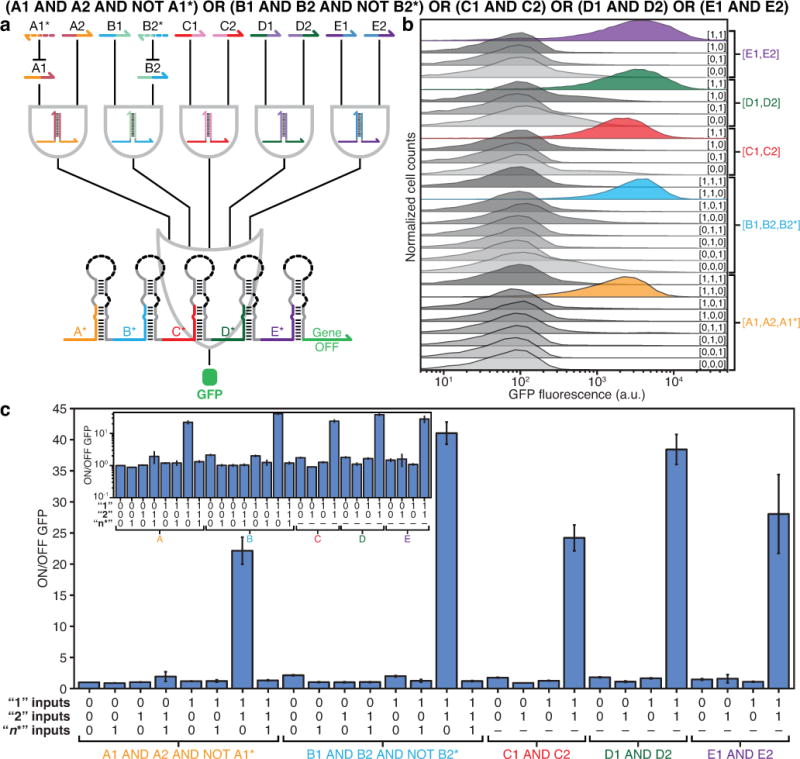
a, Schematic of the 12-input DNF expression evaluated in E. coli. b, Flow cytometry measurements show low GFP output for 23 logical FALSE states and at least 10-fold increases in GFP for the five logical TRUE states. c, ON/OFF GFP from the DNF circuit under 28 different input RNA combinations. (Inset) ON/OFF GFP on a logarithmic scale. ON/OFF GFP was determined from the geometric mean fluorescence of cells measured via flow cytometry 6 hours after induction of RNA expression. Relative errors for ON/OFF GFP were obtained by adding the relative errors of the ON and OFF fluorescence in quadrature. Errors for ON and OFF states are the SD of three biological replicates. OFF states were taken from the null-input case of the A1 AND A2 AND NOT A1* clause.
We have developed a strategy for constructing RNA-based biological circuits that exploits the programmable base-pairing properties of RNA and employs co-localized sensing and output modules to enable complex in vivo regulation (see Supplementary Information for extended discussion). These ribocomputing devices are encoded in a small genetic footprint compared to typical protein-based circuits and have the potential for scale-up based on the large sequence space afforded by RNA. The ribocomputing device architecture requires self-assembly between the input RNAs for AND and NOT logic, and hence imposes some sequence dependencies on these RNAs. The use of a co-localized gate RNA requires additional N-terminal residues in the output protein, which can interfere with its function. Incorporation of ribocomputing devices into sophisticated layered circuits, such as those made possible with advanced genetic circuit design tools15, will require systems that can provide RNAs as output species. This functionality can be implemented using gate RNAs to regulate RNA polymerases or transcription factors, which has been demonstrated previously for toehold switches17,28. Integration of mRNA-sensing ribocomputing circuits with paper-based synthetic biology systems could improve the robustness and reliability of these diagnostic tools when they are deployed in the field28,29. Detection of mRNAs and other naturally occurring RNAs as inputs for AND logic, however, will require additional synthetic RNAs to interface native transcripts. Finally, the effective use of universal Watson-Crick base pairing interactions in ribocomputing devices suggests that this strategy could be applied successfully in prokaryotic hosts beyond E. coli.
METHODS
Strains and growth conditions
The following E. coli strains were used in this study: BL21 Star DE3 (F− ompT hsdSB (rB−mB−) gal dcm rne131 (DE3); Invitrogen), BL21 DE3 (F− ompT hsdSB (rB−mB−) gal dcm (DE3); Invitrogen), MG1655Pro (F− λ− ilvG- rfb-50 rph-1 SpR lacR tetR), and DH5α (endA1 recA1 gyrA96 thi-1 glnV44 relA1 hsdR17(rK− mK+) λ−). All strains were grown in LB medium at 37°C with appropriate antibiotics: ampicillin (50 µg mL−1), spectinomycin (25 µg mL−1), chloramphenicol (17 µg mL−1), and kanamycin (30 µg mL−1).
Plasmid construction
Plasmids were constructed using PCR and Gibson assembly. DNA templates for expressing gate and input RNAs were assembled from single-stranded DNAs purchased from Integrated DNA Technologies. The synthetic DNA strands were amplified via PCR to form double-stranded DNAs. The resulting DNAs were then inserted into plasmid backbones using 30-bp homology domains via Gibson assembly30. All plasmids were cloned in the E. coli DH5α strain and validated through DNA sequencing. Backbones for the plasmids were taken from the commercial vectors pET15b, pCOLADuet, pCDFDuet, and pACYCDuet (EMD Millipore). GFPmut3b-ASV was used as the reporter for the gate plasmids. This GFP is GFPmut3b with an ASV degradation tag31. mCherry and cerulean were also used as reporter proteins for selected OR gate plasmids. Sequences of elements commonly used in the plasmids are provided in Supplementary Table S1. Sequences for all ribocomputing devices, AND-computing toehold switches, and decoy RNAs are contained in Supplementary Tables S2 to S9.
Ribocomputing device induction conditions
Unless otherwise noted, RNAs in the AND, OR, and DNF networks were expressed using T7 RNA polymerase in BL21 Star DE3, an RNase-deficient strain, with the T7 RNA polymerase induced with the addition of isopropyl ß-D-1-thiogalactopyranoside (IPTG). Two-input AND gates and the 6-input OR gate were also evaluated in BL21 DE3, a non-RNase-deficient strain, with the T7 RNA polymerase induced with IPTG. A AND (NOT B) and 6-input OR gate circuits employing the endogenous E. coli RNA polymerase were evaluated in MG1655Pro using constitutive promoters or induction via IPTG and/or anhydrotetracycline (aTc), as required. For all strains, cells were grown overnight in 96-well plates with shaking at 900 rpm and 37°C. Overnight cultures were then diluted 100-fold into fresh media and returned to shaking (900 rpm, 37°C). After 80 minutes, BL21 Star DE3 and BL21 DE3 cultures were induced with 0.1 mM IPTG, while MG1655Pro cultures were induced with the appropriate combination of 1 mM IPTG and 50 ng mL−1 aTc. Cells were returned to the shaker (900 rpm, 37°C) and measured at the specified times post-induction.
Flow cytometry measurements and analysis
Flow cytometry measurements were performed using a BD LSRFortessa cell analyzer with a high-throughput sampler. Prior to sampling, cells were diluted by a factor of ~65 into phosphate-buffered saline. Cells were detected using a forward scatter (FSC) trigger and at least 10,000 cells were recorded for each measurement. Cell populations were gated according to their FSC and side scatter (SSC) distributions as described previously17, and the GFP fluorescence levels of these gated cells were used to measure circuit output. GFP fluorescence histograms yielded unimodal population distributions and the geometric mean was employed to extract the average fluorescence across the approximately log-normal fluorescence distribution from at least three biological replicates. ON/OFF GFP levels were then evaluated by taking the average GFP fluorescence from a given combination of input RNAs and dividing it by the fluorescence from the null-input case with no cognate input RNAs expressed. Cellular autofluorescence was not subtracted prior to determining the ON/OFF ratio. The same fluorescence data analysis procedures were used for OR gates using mCherry and cerulean as reporter proteins.
Extended Data
Extended Data Figure 1. Design, activation mechanism, and characterization of AND-computing toehold switches (ACTS).
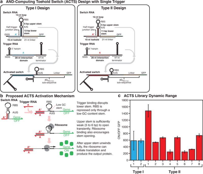
a, Nucleotide-level schematics of the Type I and Type II ACTS systems (see Supplementary Information Section 1.6 for discussion). Green and orange bases specify the output GFP sequence and the common 21-nt linker sequence used, respectively. Black bases mark biologically conserved sequences, such as the RBS, start codon, and transcriptional terminator. White bases represent those that can adopt any sequence subject to secondary structure conditions in NUPACK. Programmed hybridization domains between different strands are specified by color. b, The proposed ACTS activation mechanism in which the trigger RNA partially unwinds the switch RNA stem. The remaining weak stem, with low GC content, can interact with the ribosome to initiate translation. c, ON/OFF GFP levels measured for the ACTS systems employed in this study. ON/OFF GFP levels were determined from the geometric mean fluorescence of cells measured via flow cytometry 3 hours after induction with 0.1 mM IPTG. Relative errors for the switch ON/OFF ratios were obtained by adding the relative errors of the switch ON and OFF fluorescence measurements in quadrature. Relative errors for ON and OFF states are from the SD of three biological replicates. Flow cytometry data were produced using the same procedure in subsequent Extended Data Figures.
Extended Data Figure 2. Nucleotide-level schematics of ribocomputing devices.
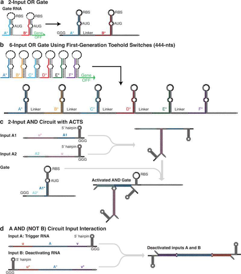
a, Secondary structure of the two-input OR gate used in Fig. 2a–d. b, Secondary structure of the six-input OR gate RNA used for circuits in Fig. 3d–f and Extended Data Figs. 7 and 8. c, Schematic of a two-input AND gate using a Type I ACTS system. A1 and A2 domains are 14-nt halves of a 28-nt-long complete trigger RNA. d, Schematic of the A AND (NOT B) circuit design. The A AND (NOT B) system design features nearly perfectly complementary trigger (input A) and deactivating (input B) RNA strands used in Fig. 2i–l. For all panels, black bases mark biologically conserved sequences, such as the RBS and start codon. White bases represent those that can adopt any sequence subject to secondary structure conditions in NUPACK. Gray bases are those whose sequences were originally determined based on secondary structure considerations for the parental toehold switches and were left constant during design of RNA circuit elements. The remaining programmed hybridization domains between different strands are specified by color. Input RNA schematics are truncated just before the transcriptional terminator sequence.
Extended Data Figure 3. Systematic study of AND gate circuit overlap domain lengths and comparison of two-input AND ribocomputing devices in different strains.

a, An early two-input AND gate was constructed from a standard toehold switch by dividing the trigger evenly into two 15-nt domains A1 and A2. Overlap domains u and u* were designed to cause the two input RNAs to hybridize and form an active trigger. b, A domain u’ was used to vary the region complementary to u* and measure its effect on expression levels. ON/OFF GFP ratios (left axis) vary as a function of the u’ domain length. The onset of substantial GFP expression coincides with the melting temperature of u’-u* hybridization rising above 37°C (right axis). c-f, Comparison of two-input AND ribocomputing devices in RNase-deficient E. coli BL21 Star DE3 and non-RNase-deficient E. coli BL21 DE3. c-d, ON/OFF GFP on linear (c) and logarithmic (d) scales measured for the two-input AND gate from Figure 2e–h. e-f, ON/OFF GFP on linear (e) and logarithmic (f) scales measured for a second two-input AND gate with an identical design but different RNA sequences.
Extended Data Figure 4. Three-, four-, and five-input AND gate systems.

a, General schematic for a three-input AND gate with GFP output. b, Nucleotide-level schematic of the activated trigger complex for the three-input AND logic circuits. c, Flow cytometry measurements from the three-input AND gate with the truth table shown in panel d. d-g, The truth tables of four different three-input AND gates. h, General schematic for a four-input AND gate with GFP output. i, Nucleotide-level schematic of the activated trigger complex for the four-input AND logic circuits. j, The truth table of an additional four-input AND gate. k, General schematic for the five-input AND gate with GFP output. l, Nucleotide-level schematic of the activated trigger complex for the five-input AND logic circuit. m, Linear-scale truth table for the five-input AND gate that displays a statistically significant difference between logical TRUE and logical FALSE conditions. n, Logarithmic truth table for the five-input AND gate. Insets of d, e, f, g, j: Logarithmic-scale plots of ON/OFF GFP for the devices.
Extended Data Figure 5. Systematic study of gate RNA performance as a function of secondary structure.

a, Nucleotide-level schematics of three four-input OR gate versions featuring small changes in secondary structure and sequence. Version 1 adopts the original secondary structures of the ACTS switch RNAs. Version 2 differs from the first gate RNA at the six positions marked in red, which weakened the hairpin secondary structure. Version 3 has an additional mismatch in the hairpin lower stem marked in blue. All other bases remained the same across the three gate RNAs. b-c, GFP fluorescence levels measured for the gate RNA versions for a panel of eight RNA triggers shown in linear (b) and logarithmic (c) scales. d, ON/OFF GFP ratios calculated for the three gate RNAs. Gate RNA version 2 provides the best combination of low leakage and high ON state GFP expression. Inset: Logarithmic-scale plot of circuit ON/OFF levels.
Extended Data Figure 6. Four- and five-input OR gate systems.
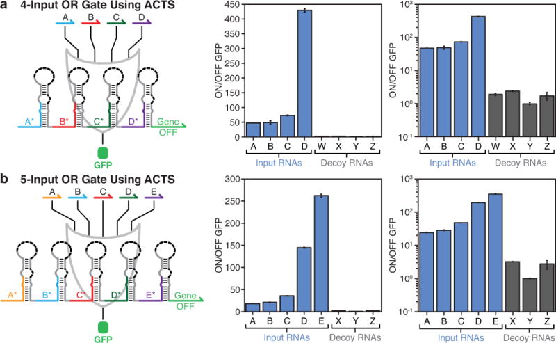
a, Linear- and logarithmic-scale plot of ON/OFF levels of a four-input OR gate constructed from ACTS hairpin modules. b, Linear- and logarithmic-scale plot of ON/OFF levels of a five-input OR gate constructed from ACTS devices. Both OR logic gates were measured 3 hours after induction of T7 RNA polymerase expression.
Extended Data Figure 7. Gate RNA regulation of mCherry and cerulean outputs with five-input OR gates and an 11-input dual OR gate circuit.

a-b, ON/OFF mCherry ratio for a five-input ACTS-based OR gate on a linear (a) and a logarithmic (b) scale. c-d, ON/OFF cerulean ratio for a five-input ACTS-based OR gate on a linear (c) and a logarithmic (d) scale. e, A six-input OR gate was used to regulate GFP and a five-input ACTS-based OR gate was used to regulate mCherry. f-g, ON/OFF ratios of the gate RNAs on linear (f) and logarithmic (g) scales. Combinations of one or two input or decoy RNAs were expressed as specified by the filled-in green (GFP inputs), red (mCherry inputs), and black (decoys) circles below each panel. All circuit responses were measured via flow cytometry 4 hours after IPTG induction.
Extended Data Figure 8. Comparison of six-input OR gate ribocomputing devices measured in RNase-deficient E. coli (BL21 Star DE3) and non-RNase-deficient E. coli (BL21 DE3, MG1655Pro).

a-b, ON/OFF GFP ratios measured for the device using T7 RNA polymerase in BL21 Star DE3 and BL21 DE3 cells on linear (a) and logarithmic (b) scales. Gate and input RNAs were expressed using the T7 RNA polymerase and measured 4 hours after induction with IPTG. c-d, ON/OFF GFP ratios obtained from the OR gate using E. coli RNA polymerase in MG1655Pro cells on linear (c) and logarithmic (d) scales. Gate and input RNAs were expressed using the E. coli RNA polymerase and measured 4 hours after induction of the gate RNA with IPTG. Input and decoy RNAs were expressed using a constitutive PN25 promoter.
Extended Data Figure 9. Evaluation of an eight-input DNF circuit.
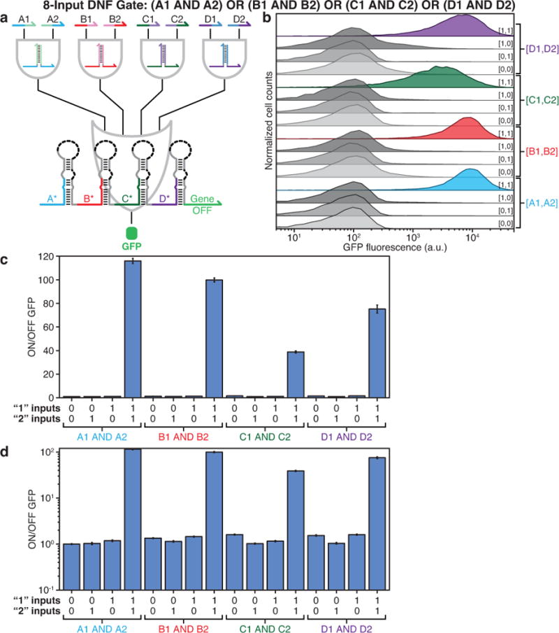
a, The eight-input DNF circuit features four two-input ANDs coupled to the four-input OR gate RNA tested in Extended Data Fig. 6a. b, GFP fluorescence histograms obtained from flow cytometry measurements of the circuit under 16 different combinations of input RNAs. c-d, ON/OFF GFP levels obtained from flow cytometry on a linear (c) and a logarithmic (d) scale.
Extended Data Figure 10. Evaluation of a 10-input DNF circuit.
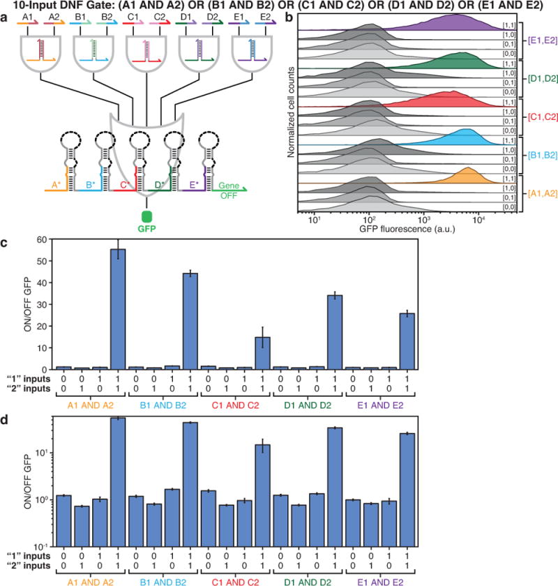
a, The 10-input DNF circuit features five two-input ANDs coupled to the five-input OR gate RNA tested in Extended Data Fig. 6b. b, GFP fluorescence histograms obtained from flow cytometry measurements of the circuit under 20 different combinations of input RNAs. c-d, ON/OFF GFP levels obtained from flow cytometry on a linear (c) and a logarithmic (d) scale.
Supplementary Material
Acknowledgments
This work was supported by NIH Director’s New Innovator and Transformative Research Awards (1DP2OD007292, 1R01EB018659), an ONR Young Investigator Program Award (N000141110914) and grants (N000141010827, N000141310593, N000141410610), NSF CAREER and Expedition in Computing Awards (CCF1054898, CCF1317291) and grants (CCF1162459, ERASynBio 1540214), and Wyss Institute Molecular Robotics Initiative to P.Y.; a DARPA Living Foundries grant (HR001112C0061) to P.A.S., P.Y., and J.J.C.; an ONR MURI Program grant and a DTRA grant (HDTRA1-15-1-0040) to J.J.C.; and Arizona State University funds to A.A.G. J.K. acknowledges a Wyss Institute Director’s Cross-Platform Fellowship.
Footnotes
Data availability. The authors declare that the main data supporting the findings of this study are available within the paper and its Supplementary Information files. Source data for Figs. 2–4 have been provided with the paper. All other data supporting the findings of this study are available from the corresponding authors on request.
Supplementary Information
Supplementary Information is linked to the online version of the paper at www.nature.com/nature.
Author Contributions
A.A.G conceived of the study, designed and performed the experiments, analyzed the data, supervised D.M. and wrote the paper. J.K. conceived of the study, designed and performed the experiments, analyzed the data and wrote the paper. D.M. performed experiments and analyzed the data. P.A.S. supervised the study. J.J.C. supervised the study. P.Y. conceived of and supervised the study, interpreted the data, and wrote the paper. All authors reviewed and approved the manuscript.
A patent has been filed based on this work.
Competing financial interests
A provisional US patent has been filed based on this work. P.Y. is the co-founder of Ultivue Inc. and NuProbe Global.
References
- 1.Cameron DE, Bashor CJ, Collins JJ. A brief history of synthetic biology. Nature Reviews Microbiology. 2014;12:381–390. doi: 10.1038/nrmicro3239. [DOI] [PubMed] [Google Scholar]
- 2.Gardner TS, Cantor CR, Collins JJ. Construction of a genetic toggle switch in Escherichia coli. Nature. 2000;403:339–342. doi: 10.1038/35002131. [DOI] [PubMed] [Google Scholar]
- 3.Elowitz MB, Leibler S. A synthetic oscillatory network of transcriptional regulators. Nature. 2000;403:335–338. doi: 10.1038/35002125. [DOI] [PubMed] [Google Scholar]
- 4.Danino T, Mondragon-Palomino O, Tsimring L, Hasty J. A synchronized quorum of genetic clocks. Nature. 2010;463:326–330. doi: 10.1038/nature08753. [DOI] [PMC free article] [PubMed] [Google Scholar]
- 5.Bashor CJ, Helman NC, Yan S, Lim WA. Using Engineered Scaffold Interactions to Reshape MAP Kinase Pathway Signaling Dynamics. Science. 2008;319:1539–1543. doi: 10.1126/science.1151153. [DOI] [PubMed] [Google Scholar]
- 6.Daniel R, Rubens JR, Sarpeshkar R, Lu TK. Synthetic analog computation in living cells. Nature. 2013;497:619–623. doi: 10.1038/nature12148. [DOI] [PubMed] [Google Scholar]
- 7.Rinaudo K, et al. A universal RNAi-based logic evaluator that operates in mammalian cells. Nature Biotechnology. 2007;25:795–801. doi: 10.1038/nbt1307. [DOI] [PubMed] [Google Scholar]
- 8.Win MN, Smolke CD. Higher-order cellular information processing with synthetic RNA devices. Science. 2008;322:456–460. doi: 10.1126/science.1160311. [DOI] [PMC free article] [PubMed] [Google Scholar]
- 9.Tamsir A, Tabor JJ, Voigt CA. Robust multicellular computing using genetically encoded NOR gates and chemical ‘wires’. Nature. 2011;469:212–215. doi: 10.1038/nature09565. [DOI] [PMC free article] [PubMed] [Google Scholar]
- 10.Xie Z, Wroblewska L, Prochazka L, Weiss R, Benenson Y. Multi-Input RNAi-Based Logic Circuit for Identification of Specific Cancer Cells. Science. 2011;333:1307–1311. doi: 10.1126/science.1205527. [DOI] [PubMed] [Google Scholar]
- 11.Moon TS, Lou C, Tamsir A, Stanton BC, Voigt CA. Genetic programs constructed from layered logic gates in single cells. Nature. 2012;491:249–253. doi: 10.1038/nature11516. [DOI] [PMC free article] [PubMed] [Google Scholar]
- 12.Ausländer S, Ausländer D, Müller M, Wieland M, Fussenegger M. Programmable single-cell mammalian biocomputers. Nature. 2012;487:123–127. doi: 10.1038/nature11149. [DOI] [PubMed] [Google Scholar]
- 13.Bonnet J, Yin P, Ortiz ME, Subsoontorn P, Endy D. Amplifying genetic logic gates. Science. 2013;340:599–603. doi: 10.1126/science.1232758. [DOI] [PubMed] [Google Scholar]
- 14.Tabor JJ, et al. A synthetic genetic edge detection program. Cell. 2009;137:1272–1281. doi: 10.1016/j.cell.2009.04.048. [DOI] [PMC free article] [PubMed] [Google Scholar]
- 15.Nielsen AAK, et al. Genetic circuit design automation. Science. 2016;352 doi: 10.1126/science.aac7341. [DOI] [PubMed] [Google Scholar]
- 16.Kiani S, et al. CRISPR transcriptional repression devices and layered circuits in mammalian cells. Nature Methods. 2014;11:723–726. doi: 10.1038/nmeth.2969. [DOI] [PMC free article] [PubMed] [Google Scholar]
- 17.Green AA, Silver PA, Collins JJ, Yin P. Toehold Switches: De-Novo-Designed Regulators of Gene Expression. Cell. 2014;159:925–939. doi: 10.1016/j.cell.2014.10.002. [DOI] [PMC free article] [PubMed] [Google Scholar]
- 18.Braich RS, Chelyapov N, Johnson C, Rothemund PWK, Adleman L. Solution of a 20-Variable 3-SAT Problem on a DNA Computer. Science. 2002;296:499–502. doi: 10.1126/science.1069528. [DOI] [PubMed] [Google Scholar]
- 19.Chen YJ, Groves B, Muscat RA, Seelig G. DNA nanotechnology from the test tube to the cell. Nature Nanotechnology. 2015;10:748–760. doi: 10.1038/nnano.2015.195. [DOI] [PubMed] [Google Scholar]
- 20.Qian L, Winfree E, Bruck J. Neural network computation with DNA strand displacement cascades. Nature. 2011;475:368–372. doi: 10.1038/nature10262. [DOI] [PubMed] [Google Scholar]
- 21.Elbaz J, et al. DNA computing circuits using libraries of DNAzyme subunits. Nature Nanotechnology. 2010;5:417–422. doi: 10.1038/nnano.2010.88. [DOI] [PubMed] [Google Scholar]
- 22.Lake A, Shang S, Kolpashchikov DM. Molecular Logic Gates Connected through DNA Four-Way Junctions. Angewandte Chemie International Edition. 2010;49:4459–4462. doi: 10.1002/anie.200907135. [DOI] [PubMed] [Google Scholar]
- 23.Zhu J, Zhang L, Dong S, Wang E. Four-Way Junction-Driven DNA Strand Displacement and Its Application in Building Majority Logic Circuit. ACS Nano. 2013;7:10211–10217. doi: 10.1021/nn4044854. [DOI] [PubMed] [Google Scholar]
- 24.Rodrigo G, Landrain TE, Jaramillo A. De novo automated design of small RNA circuits for engineering synthetic riboregulation in living cells. Proceedings of the National Academy of Sciences of the United States of America. 2012;109:15271–15276. doi: 10.1073/pnas.1203831109. [DOI] [PMC free article] [PubMed] [Google Scholar]
- 25.Chappell J, Takahashi MK, Lucks JB. Creating small transcription activating RNAs. Nature Chemical Biology. 2015;11:214–220. doi: 10.1038/nchembio.1737. [DOI] [PubMed] [Google Scholar]
- 26.Chen X. Expanding the Rule Set of DNA Circuitry with Associative Toehold Activation. Journal of the American Chemical Society. 2012;134:263–271. doi: 10.1021/ja206690a. [DOI] [PMC free article] [PubMed] [Google Scholar]
- 27.Genot AJ, Bath J, Turberfield AJ. Combinatorial Displacement of DNA Strands: Application to Matrix Multiplication and Weighted Sums. Angewandte Chemie. 2013;125:1227–1230. doi: 10.1002/anie.201206201. [DOI] [PubMed] [Google Scholar]
- 28.Pardee K, et al. Paper-Based Synthetic Gene Networks. Cell. 2014;159:940–954. doi: 10.1016/j.cell.2014.10.004. [DOI] [PMC free article] [PubMed] [Google Scholar]
- 29.Pardee K, et al. Rapid, Low-Cost Detection of Zika Virus Using Programmable Biomolecular Components. Cell. 2016;165:1255–1266. doi: 10.1016/j.cell.2016.04.059. [DOI] [PubMed] [Google Scholar]
- 30.Gibson DG, et al. Enzymatic assembly of DNA molecules up to several hundred kilobases. Nature Methods. 2009;6:343–345. doi: 10.1038/nmeth.1318. [DOI] [PubMed] [Google Scholar]
- 31.Andersen JB, et al. New unstable variants of green fluorescent protein for studies of transient gene expression in bacteria. Applied and Environmental Microbiology. 1998;64:2240–2246. doi: 10.1128/aem.64.6.2240-2246.1998. [DOI] [PMC free article] [PubMed] [Google Scholar]
Associated Data
This section collects any data citations, data availability statements, or supplementary materials included in this article.