Abstract
This paper presents a system of two double-gimbal control moment gyroscopes (CMGs) for providing ungrounded kinesthetic haptic feedback. By spinning a second flywheel opposite the first, and rotating them through opposite trajectories, undesired gyroscopic effects can be eliminated, isolating a single torque axis. This produces a moment pulse proportional to the flywheel spin speed and rotation speed. Rotating the CMG gimbals quickly in one direction, then resetting them more slowly generates repeated torque pulses indicating a clear direction cue. We present the mathematical model for moments produced by this system and verify that the performance of our device matches this model. Using these asymmetric moment pulses, we provide haptic cues to participants in two studies. In the first study, users simply identify the direction of torque cues. In the second study, we use the torque pulses to guide users to target orientations. Performance in both studies shows that this system has the potential to provide useful guidance for applications where ungrounded haptic feedback is desired.
Keywords: haptic display, kinesthetic devices, system design and analysis
1. Introduction
1.1. Motivation
Traditional kinesthetic devices, which use ground-based reaction forces transmitted to the user via kinematic chains of rigid links and joints, have limited portability. In contrast, ungrounded haptic feedback devices provide users with cutaneous or kinesthetic feedback applied over a large workspace. Many portable haptic feedback approaches stimulate only the skin, i.e. providing tactile or cutaneous feedback using vibration [1], skin deformation [2], [3], or by changing shape [4]. These devices have many benefits including their small size, light weight, and, in many cases, wearability. However, they cannot generate kinesthetic forces on the limb. The feedback must be processed and interpreted by the human before affecting physical behavior [5]. Alternatively, body-grounded kinesthetic devices allow movement of the body through a large workspace while providing forces that can dynamically affect movement. These devices can potentially generate unrealistic or confusing haptic signals because they require reaction forces between different limb segments [6]. Ungrounded kinesthetic feedback generates forces and torques on the body relative to an inertial ground. They directly affect physical dynamics, potentially providing clearer haptic signals. Applications for ungrounded kinesthetic feedback include direction guidance cues via held or worn devices and display of inertia from held virtual objects. For example, this type of haptic system could be used to provide intuitive pedestrian navigation in situations where visual feedback is unavailable or unsafe, to provide guidance or feedback in pointing or aiming tasks where portability is desirable such as robotic teleoperation outdoors, and to enable touch interactions with objects in virtual reality environments.
1.2. Related Work
Ungrounded kinesthetic cues can be generated through the use of reaction wheels or control moment gyroscopes (CMGs) to produce torque without external grounding. These devices are commonly used for attitude control of spacecraft [7], [8]. Both reaction wheels and CMGs, such as the device shown in Fig. 1, take advantage of conservation of angular momentum to generate large moments. Reaction wheel devices, which change the speed of a spinning flywheel, but not its orientation, have been used in several haptic devices [9]—[12]. Accelerating or braking the flywheel changes the angular momentum in the direction of the flywheel axis, so there is a reaction moment about that axis transmitted to the user holding the device. When the speed of the flywheel saturates, no additional output moment is possible. These devices must have a separate flywheel for each desired degree of freedom. To produce noticeable torques, they require heavy flywheels, large accelerations, and powerful motor brakes.
Fig. 1.
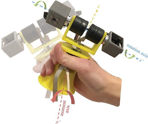
Dual-flywheel ungrounded haptic feedback device. Two flywheels rotated about a horizontal axis x’ by opposite angles φ generates a net moment about a perpendicular axis y’.
In contrast, CMG devices change flywheel orientation rather than speed. They can produce larger moments using lighter and smaller flywheels. CMGs have also been applied with some success in haptics. Typically, a single flywheel is mounted on two gimbals to allow rotation about multiple axes [13]—[15]. The torque axis produced is in the direction of the change in angular momentum vector, which in this case is orthogonal to both the spin axis of the flywheel and the gimbal rotation axis. Because the reaction torque is provided by the structure surrounding the motor rather than the motor itself, the magnitude is not limited to the motor’s torque capabilities. As a flywheel gimbal rotates, the torque vector generated also rotates, eventually switching directions completely if the gimbal reaches 180° of rotation. By rotating through a smaller angle quickly and then resetting the flywheel to its starting position more slowly, single-CMG haptic devices have been able to provide useful directional guidance [15]. With such an asymmetric rotation pattern, the fast pulse produces a stronger moment than the slow return, resulting in an identifiable direction cue. However, the changing direction of the moment vector and the angular acceleration of the flywheel through these pulses add orthogonal components to the output moment that make it more difficult for a user to feel a distinct direction. These gyroscopic effects detract from the sensation provided to the user.
With two CMG devices, it is possible to cancel the components of the moment about all but one axis. By spinning the two flywheels in opposite directions and reorienting them about opposite angles, the torques about the main axis sum while the other axes are canceled. Because of the clarity of the torque pulses, smaller, lighter flywheels can be used with better performance than previous CMG-based haptic devices such as the system in [15]. Little work has been done using scissored pairs of CMGs for haptics applications. They have been applied in simple navigation experiments [16] and for human balance assistance [17], but have potential for a wider range of guidance applications.
1.3. Contributions
In previous research, we demonstrated that users are able to easily determine direction cues from a hand-held device consisting of two double-gimbal CMGs [18]. This novel combination of the benefits of asymmetric pulses and scissored CMGs results in effective kinesthetic feedback from an ungrounded device. Here, we present an improved design of our hand-held dual CMG device (Fig. 1). Using this compact, light-weight system, we show that directions can be easily identified, and we extend its use to a closed-loop orientation-guidance task. The device’s performance in both tasks shows its potential for ungrounded haptics applications.
2. CMG Output Moments
Due to conservation of angular momentum, a reaction moment is generated on a system when a spinning flywheel is rotated about an axis. This Section presents a mathematical model for a single CMG and a scissored-pair of CMGs to demonstrate the advantages of a scissored-pair CMG device for haptic applications. The axes are depicted in Fig. 2(a) and 2(b).
Fig. 2.
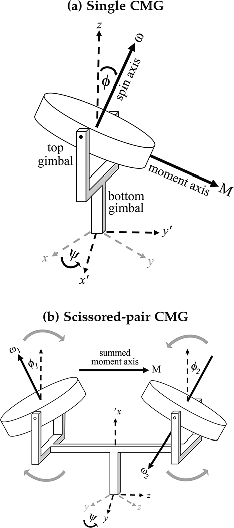
(a) A model of a double-gimbal control moment gyroscope. The bottom gimbal rotates the flywheel about the z axis by an angle ψ, then the top gimbal rotates the flywheel about the new x’ axis by an angle φ. This generates a moment perpendicular to the spin axis of the flywheel. (b) When two double-gimbal CMGs are spinning in opposite directions, and are rotated through reverse trajectories, the sum of the moments does not rotate with the flywheels.
2.1. Single Double-Gimbal CMG
We model a flywheel F rotating about its center of mass on two gimbals and mounted to a stationary handle in a Newtonian reference frame N. The bottom gimbal rotates about the z axis with angular velocity ψ, and the top gimbal rotates with angular velocity φ about the x’ axis (the x axis rotated first by the bottom gimbal).
The angular momentum is
| (1) |
where is the moment of inertia dyadic of the flywheel and N ω F is the total angular velocity of the flywheel in N. The moment output is the angular momentum differentiated with respect to the frame N:
| (2) |
which expands to
| (3) |
where is the total angular acceleration of the flywheel with respect to frame N.
To simplify the results, we assume that the gimbal inertias are negligible compared to the flywheel, the flywheel has a constant spin speed ω, and the flywheel center of mass is centered on the gimbal axes and remains stationary. We also limit the rotation to only the top gimbal, so the bottom gimbal is fixed at ψ = 0 and ψ = 0. In this case, the x’ and y’ axes are equal to the x and y axes, respectively. Equation 3 becomes
| (4) |
where φ is the top gimbal angle, and Ixx and Izz are the radial and axial moments of inertia, respectively. At φ = 0, the flywheels are both facing up, so that the ω vectors are in line with the z axis. Over the course of a rotation from —φ to φ about the x axis, the net moment produced would be about only the y axis. But Equation 4 shows that the instantaneous moment throughout the rotation has x and z components. The torque axis is always perpendicular to the flywheel axis and the axis of rotation, so as the flywheel rotates about the x axis, the resulting torque axis is constantly rotating as well, eventually pointing in the reverse direction if the rotation reaches 180°. This rotating torque axis introduces a z torque component. The x component is due to the acceleration of the gimbal through the trajectory. For applications such as haptic guidance, it is important that moment cues are clear. Transient moment components in directions orthogonal to the desired haptic cue make it difficult for a user to interpret the guidance.
One method of addressing this shifting torque vector is to pulse the flywheels through only a small angle so that the change in the torque axis direction is not very noticeable. An asymmetric pattern of a fast pulse and a slower return to the starting orientation can generate repeated cues with little direction change [15], and rotating through only a small angle can reduce the z component in Equation 4. Using a smaller angle limits the speed that the gimbal can reach during its rotation while maintaining a smooth trajectory. Because the y moment is proportional to the speed of the rotation, φ, this reduces the magnitude of torques that can be generated. If trajectory smoothness is sacrificed, high speeds can be reached through a small rotation angle, but the large accelerations required result in large x axis moment components, and the changing z component is still not eliminated completely. Fig. 3(a) shows a typical asymmetric pulse and return for one flywheel. Here a rotation from —36° to 36° and back about the x axis is completed using a minimum snap trajectory, which minimizes the second derivative of acceleration. This trajectory reduces the x component to almost zero even with only one CMG. Although the y component, the desired axis, is the largest, we would like to eliminate the z component. This is possible through the use of a second double-gimbal CMG.
Fig. 3.
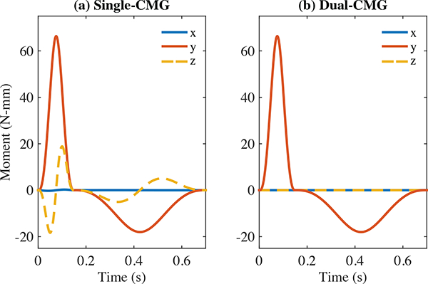
(a) Estimated torque output from rotating a single CMG. When the intended pulse axis is the y axis, there are orthogonal components in the x and z direction that make the haptic cue less clear. (b) Estimated torque output from counter-rotating two CMGs (each with half the inertia of the single-flywheel). The x and z components of the two flywheels cancel, and the y components of each flywheel sum.
2.2. Scissored Pair of Double-Gimbal CMGs
For haptics applications, a scissored pair of double-gimbal CMGs is advantageous over a single CMG because a single axis can be isolated for each torque pulse. By spinning a second flywheel in the opposite direction, and rotating it through a reverse trajectory of the first flywheel, as in Fig. 2(b), all but the desired y moment is eliminated. Each CMG generates a positive moment in the y direction, but the second CMG generates moments about the x and z axes that are negative of those generated by the first CMG. If both flywheels have the same moment of inertia, the orthogonal components will perfectly cancel, as shown in Fig. 3(b).
Again, to simplify the results, the bottom gimbal is stationary throughout the rotation of the upper gimbal, and is held at ψ = 0. The flywheel speeds are constant (ω1 = —ω2 = ω) and the top gimbal angles are scissored (φ2 = — φ1 = φ). The angular momentum of the scissored-pair CMG system D at any instant is
| (5) |
The instantaneous moment is
| (6) |
The x and z components no longer exist. Because the torque vector does not change direction, larger angles of rotation and speeds φ can be reached, generating strong moments about only a single axis. Additionally, because the two flywheels are spinning in opposite directions, the total angular momentum of the system is zero when the gimbals are at rest, and the device does not resist external rotations of the entire system as a single flywheel system would.
When ψ = 0, the y axis is isolated, but any other horizontal torque axis can be generated by rotating the bottom gimbals by φ before pulsing the top gimbals through φ. Rotations done to reach these different axes can be slow enough that moments generated are not noticeable to the user. To reach vertical torque axes, the speed of the flywheels, ω, could be changed while they are pointed upward, as was done in [18]. This is the way reaction wheels generate torques. However, larger moments can be generated if the flywheels are used as CMGs and the flywheel speed is not changed. By rotating the pulsing trajectory of the flywheels by 90° so that the midpoint is toward the side rather than upwards, vertical torque cues can be generated at the same magnitudes as the horizontal torque cues. This corresponds to one flywheel rotating through (—φ — 90) to (φ — 90) and the other through (φ — 90) to (—φ — 90). Adjusting this midpoint anywhere between vertical and 90° to the side allows us to reach diagonal torque axes as well. In this way, any three-dimensional moment vector can be isolated by the scissored-pair CMG system.
3. Device Design
This device, shown in Fig. 1, uses two Lynxmotion 2400 KV brushless motors as flywheels (2400 RPM/volt). The outer casing of the motor rotates with the shaft, acting as a flywheel, with its mass primarily at its outer radius. The mass of each motor is 13.4 g. The rotating component has an outer radius of 23 mm, an axial inertia of 1.98 10−6 kg m2, and a radial inertia of 1.03 10−6 kg m2. We spin the brushless motors at a constant speed of approximately 20,000 rpm.
Each flywheel motor is rotated about its center of mass by a Faulhaber Flat DC Micromotor with a 33:1 gearbox and incremental encoders (2619S012SR 33:1 IE2–16). These two motors are mounted to an additional gimbal rotated by a third Faulhaber Flat DC Micromotor with a 207:1 gearbox and incremental encoders (2619S012SR 207:1 IE2–16) to limit the loss of torque about the axial direction. An earlier version of the device presented in [18] used two separate bottom gimbal motors. Using one motor reduces the weight and size of the system. It also ensures the top gimbals are rotated to exactly the same angle.
A Sensoray 826 PCI card controls the system. A 13V external power supply (Mouser) and custom built linear current amplifiers (LM675T) with a gain of 0.5 A/V power the three gimbal motors. A separate 12V power supply is used to power the brushless motors and the control circuitry. An Ascension trakSTAR six degree-of-freedom magnetic tracking system measures the orientation of the device handle at 100 Hz. The magnetic sensor is rigidly attached to the center of the handle. We kept metal objects away from the device and tracker, and we used Ascension’s proprietary software to verify that the quality of the tracking signal was not reduced by proximity to the motors in the device.
The motors are controlled using a PD controller tuned so that the gimbal motion satisfactorily tracks the asymmetric trajectory and has minimal overshoot. To minimize overshoot and accompanying torque effects, a smooth trajectory from the starting to ending angle is necessary. We used a trajectory that minimizes snap (the second derivative of acceleration). The flywheels were rotated from −36°to 36° from a specified midpoint during the fast pulse, and returned to −36° on the slow return pulse. Preliminary experiments found that a pulse time of 150 ms and a return-time of 550 ms provides clear, smooth torque pulses. This also provides sufficient time between pulses for users to move in response to each guidance cue.
The gimbals and handle are manufactured from 3D-printed ABS plastic. The handle was designed with an inwardly curved shape to enable users to hold it loosely without dropping it. The entire device weighs 197.7 g. The device is symmetric in the handle’s x-z and y-z planes, and the center of mass is centered 3 mm above the bottom edge of the lower gimbal. The moments of inertia about the x, y, and z axes are 0.0012, 0.0065, and 0.0046 kgm2, respectively, with the upper gimbals aligned along the x-axis. The center of mass remains stationary, but the moments of inertia change slightly depending on gimbal position. The device presented here is tethered to the computer, power supplies, and magnetic tracking system. Future versions could be fully portable by replacing the orientation tracking with inertial measurement units and including on-board controllers and batteries.
4. Device Performance
We verified the single-axis moment outputs of our dual CMG device with an ATI Mini45 force/torque sensor (Fig. 4). The resulting moment pulses are shown in Fig. 5. The upper gimbals rotate through a minimum snap trajectory from —36° from vertical to 36° for φ1 and 36° to —36° for φ2 to generate the strong pulse over 150 ms. They then return through another minimum snap trajectory over 550 ms. The measured torque closely matches the theoretical output in Fig. 3. The x component is small in all cases because of the minimum snap trajectory. When executing a moment cue about only the y axis, the z component can be seen in the left and right CMGs’ outputs separately, but because they oppose each other, the total z component when the CMGs are actuated together is reduced to approximately zero. Vibration noise from the motors introduces higher frequency components. Losses in the joints of the device reduce the output torque magnitude slightly from the theoretical magnitude. The asymmetric pattern produces a peak for the torque pulse (51.19 N-mm) that is much larger than for the resetting torque (−14.25 N-mm). In this way, users feel a repeated torque cue about the positive y axis, and ideally neglect the smaller —y torque during resetting.
Fig. 4.
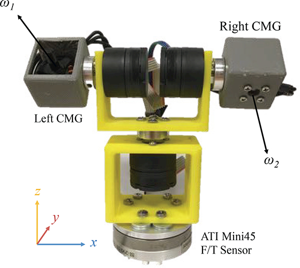
The double-gimbal CMG system mounted on a Mini45 force/torque sensor for measuring torque output.
Fig. 5.
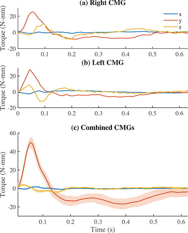
Output torque pulse magnitudes in the y direction. (a) and (b) show the two CMG components separately. (c) When both CMGs pulse, the x and z components cancel to approximately zero, and the y components sum. Here, the mean torque for ten repeated pulses is plotted about each axis and shown with an envelope depicting the standard deviation.
Fig. 6 shows that the torque axis is almost completely in a single direction over the course of each pulse, in this case in the horizontal plane at 45°. There is a small difference in the direction for the ascending and descending part of the pulse. In Fig. 6(a), the direction of the pulse changes by about 7° between the acceleration and deceleration of the top gimbal. This is because the bottom gimbal motor shaft rotates slightly due to the torque, changing the angle of the top gimbal. This could be eliminated with the use of a higher power motor, but this motor was chosen in an effort to maximize performance while keeping the device at a holdable size. Elhajj et al. found that at least 15° of difference was necessary for users to consistently discriminate force directions from a joy stick [19]. The torque generated by our device is applied to the user’s hand as forces at the top and bottom of their grip, so the direction threshold should be similar. Therefore, this change of 7° should not be noticeable to the user.
Fig. 6.
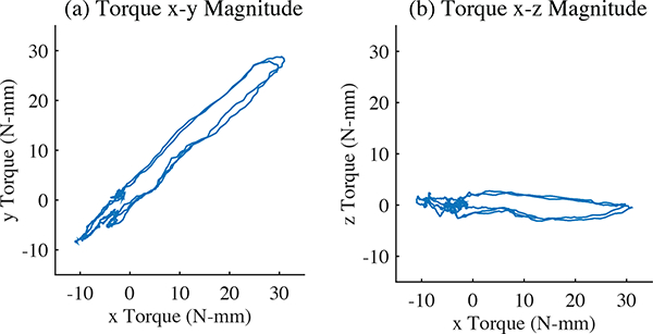
Measurements of three repeated pulses at a 45° angle. (a) The magnitude in the horizontal plane (x-y axis). (b) The magnitude in the vertical plane (y-z axis).
In Fig. 6(b), there is also a difference in the magnitude of the torque about the z axis of approximately 4.5 N-mm over the course of a pulse. The first part of the fast pulse has a slight positive z torque, and the second part has a slight negative z torque, which is also evident in Fig. 5(c). This could be an effect of slightly imperfect matching in the speeds of the flywheels or the rotation of the top gimbals. This difference is much smaller than that which would be produced by the rotating axis of a single-CMG system. The just-noticeable-difference in magnitude for torque is 12.7% [20], which would be 6.50 N-mm for our 51.19 N-mm pulses. Therefore, this change is also smaller than a human’s perceptual capabilities could identify. Small twisting torques of about 10 N-mm are generated when the bottom gimbal rotates to change the torque axis between cues. This is much smaller than the strong torque pulses and is not very noticeable to the user. These rotations are done slowly, but if very fast changes were desired, the torque generated would have to be considered. Improvements in device design to reduce the inertia about the vertical axis could lessen this effect.
5. User Study I: Direction Identification
To test the effectiveness of our device for conveying different directions to human users, we conducted a user study in which we provided cues for rotations about the six cardinal torque axes (tilting left, right, back, and forward, and twisting clockwise and counterclockwise). Twelve righthanded people between the ages of 23 and 44 participated in the study, which was similar to the experiment completed in [18]. The study was approved by the Stanford University Internal Review Board, and users gave informed consent.
5.1. Experimental Setup
The experimental setup is shown in Fig. 7. Users were seated at a desk and held the device with their right hand. Users were instructed to grip the device as shown in Fig. 1, and to hold it loosely but without risk of dropping it. A divider blocked the device from their view, and noise-canceling headphones playing white noise blocked any sounds from the device. They interacted with a computer keyboard to advance each trial and input the directions they felt. After each trial, users received feedback on the correct direction.
Fig. 7.
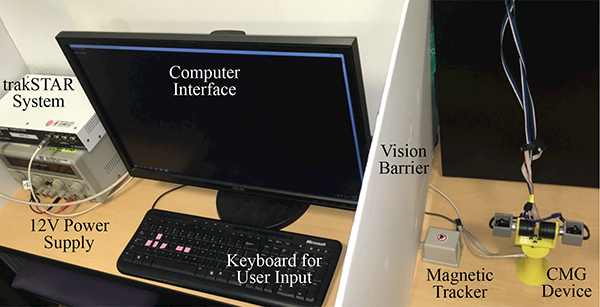
The experimental setup for both User Study I and User Study II. In the first study users interacted with the computer keyboard to select the direction toward which they perceived the torque pulses. In the second study, the magnetic tracking system recorded orientation, and closed-loop guidance was provided. In both studies, users held the device behind a barrier to block it from their sight.
5.2. Procedure
Each user completed 24 practice trials to become familiar with the device before completing 24 experimental trials. They identified whether pulses were toward the left, toward the right, forward, backward, or twisting clockwise (CW) or counterclockwise (CCW) as viewed from above the device. The 24 trials included four occurrences of each direction. Three different pseudo-random condition orders were used in the study, such that four different users completed each condition order. After the study, users completed a survey in which they were asked about the task difficulty and strategies used to complete the task.
Users started each trial with the computer keyboard. Torque pulses were then repeated in the same direction until the user selected an answer using the keyboard. The correct direction was displayed on the screen after each input. For all trials, the torque pulses were 150 ms long with a peak magnitude of 51.19 Nmm, and the return pulse was 550 ms long with a peak magnitude of 14.25 Nmm, as in Fig. 5(c).
5.3. Results
The correct and incorrect response rates are depicted in a confusion matrix (Table 1). Users made few mistakes in identifying distinct orthogonal directions. Incorrect answers were given in only two out of the 288 total trials, resulting in a success rate of 99.3%. The time taken to identify cue directions is shown in Fig. 8. In general, users were able to identify directions quickly (mean = 4.52 s, SD = 1.51 s). Because there is an inherent 700 ms length of time for each torque cue (in addition to time required to rotate the bottom gimbal), this mean response time corresponds to an average of about six pulses. A repeated measures ANOVA identified significant performance differences between several directions (F(5,12) = 13.935, p < 10−11). A post-hoc multiple comparison test using a Bonferroni correction revealed that the two slowest directions on average - right and backward - were significantly slower than the two quickest directions - left and counterclockwise, as shown with brackets in Fig. 8.
Table 1.
Confusion Matrix for User Study I: Direction Identification
| Correct Direction | User Responses | |||||
|---|---|---|---|---|---|---|
| Left | Right | Forward | Backward | CW | CCW | |
| Left | 100 | 0.0 | 0.0 | 0.0 | 0.0 | 0.0 |
| Right | 0.0 | 97.9 | 0.0 | 2.1 | 0.0 | 0.0 |
| Forward | 0.0 | 0.0 | 100 | 0.0 | 0.0 | 0.0 |
| Backward | 0.0 | 0.0 | 0.0 | 100 | 0.0 | 0.0 |
| CW | 2.1 | 0.0 | 0.0 | 0.0 | 97.9 | 0.0 |
| CCW | 0.0 | 0.0 | 0.0 | 0.0 | 0.0 | 100 |
Cells are shaded corresponding to percentage of responses.
Fig. 8.
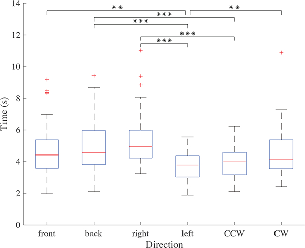
User Study I: Length of time taken to identify direction cues for each direction with quartiles and outliers depicted. n = 12 (**p < 0.01, ***p < 0.001).
5.4. Discussion
5.4.1. Discrimination
The success rate using this device is higher than in similar studies for reaction-wheel devices [10] or single-CMG devices [15]. In [10], a reaction-wheel device was used in a discrimination study of eight directions. Torque cues of approximately 50 N-mm and 70 N-mm were tested, and responses were correct only 70% of the time. In [15], asymmetric torque pulses were rendered from a single-CMG device with magnitudes ranging from 3 N to 60 N. Success rates for discriminating between between only left and right were below 80% for all magnitudes. With the dual-CMG device presented here, users were able to distinguish the six directions in this study almost perfectly with cues of a comparable magnitude.
An earlier version of this dual-CMG device was used in a similar, previous direction identification study [18]. The torque pulses delivered from that device were a maximum of 15 N-mm, which is less than 30% of the magnitude used in this study. The current device, although smaller and lighter, has much faster-spinning flywheels, enabling it to generate larger torque pulses. Additionally, in the previous experiment, the twisting torques were generated by changing the flywheel speed rather than rotating the flywheels, which limited torque magnitude. In this study, all torque pulses were generated by rotating the flywheel gimbals, enabling higher magnitudes. The combination of the improved twisting torques and overall increased torque magnitude has improved the rate of correct responses from 80% in the previous study to nearly 100% in this study.
5.4.2. Response Time
In general, the times taken to determine the direction were quick. The response time was slightly longer than in the previous experiment in [18] because the pulses were at a lower frequency in this study. Users were instructed to prioritize correct answers over speed, so the recorded times are likely conservative. Back and right took longer than the other directions to identify. In post-experiment surveys, several users identified these as the most difficult directions.
There are several reasons for why torques toward the back and the right were more difficult for users to identify. In the hand, the density of mechanoreceptors is highest in the fingertips and decreases toward the palm and wrist [21]. Torque pulses toward the left and front were mainly engaging the fingers, whereas torque pulses toward the right and back were mainly engaging the palm.
Additionally, torques in these directions must work against a larger mass and stiffer part of the hand; pulses toward the back push against the wrist, and pulses toward the right push against the palm of the right hand. Because this device is ungrounded, the acceleration produced is inversely proportional to the inertia of the system. The mass of the hand is larger on the palm side (toward the right) and where the wrist connects (toward the back). The fingers are lighter, and therefore easier to accelerate with the ungrounded torque pulses produced by our device. Weaker acceleration cues toward the back and to the right may make these directions harder to perceive.
Finally, prior work on rotational motion of an object in a precision grasp showed that users responded more quickly to rotations in “dangerous” directions in which the object was less secure [22]. The palm and wrist directions prevent more of the handle’s motion, making them safer directions than toward the fingers. This difference in security may affect time to identify direction. In the future, we may study this phenomenon by adjusting the magnitude of torque pulses in each direction to equalize these differences or by testing the left hand as well to see if the same effect arises with pulses toward the left and back. A similar device that is fingertip-mounted or that could be pinched only in the fingers could have improved performance because it would engage an area of higher sensitivity and lower mass and impedance.
Despite the differences in response time, users were almost completely accurate in identifying directions. The strong performance in this direction-identification study motivated the use of our device in more complicated scenarios. We explored the performance of our system at providing cues in more arbitrary torque directions through a second user study.
6. User Study II: Closed-loop Orientation Center-out Reaches
The same twelve right-handed people participated in a second user study in which they responded to cues from the CMG device that guided them toward a desired tilt orientation using closed-loop torque pulses. Target orientations were defined as unit vectors with which to align the device’s handle in two degrees of freedom. They only depended on handle tilt. If the handle was in line with the target vector with any twist about its own axis, the target was reached. Targets were chosen at three different angles down from vertical: 45°, 60°, and 72°. These magnitudes were selected to be reasonably far from vertical, but were within a comfortable range of motion. Targets were selected pseudo-randomly and include rotations that would not be obvious to users (such as 90° and 45° spacings between targets might be). They are shown from above projected onto the unit sphere in Fig. 9.
Fig. 9.
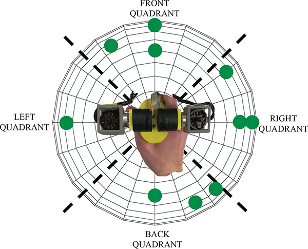
User Study II: The locations of targets used in the study. The device’s workspace is divided into left, front, right, and back quadrants for analysis.
Closed-loop guidance cues were provided to the user throughout each trial. The axis about which the user should rotate the handle was continuously calculated by taking the cross-product of the current handle axis and the target vector. Transforming this axis into the reference frame of the handle and rotating by —90° gives the angle that the bottom gimbal of the device should align with in order to generate the appropriate torque axis. The motion of the top gimbals was from —36° to 36° for all pulses, as in the previous experiments. The asymmetric pulses were 150 ms for the fast pulse and 550 ms for the return. Although the device is capable of delivering compelling twisting cues, as shown in Study I, the target vectors were defined without consideration of twist about the handle. Therefore only tilting torques around axes that were in the handle’s x-y plane were applied to the device to guide the user.
6.1. Experimental Setup
The experimental setup was the same as in the direction-identification study, shown in Fig. 7. Users sat at a desk, holding the device with their right hand, and were blocked from seeing and hearing the device. A magnetic sensor was rigidly attached to the handle, and an Ascension trakSTAR system measured the handle orientation.
6.2. Procedure
Users completed a series of trials similar to a center-out reach task in which they acted on guidance from the device.They began each trial with the device in a vertical orientation and responded to a series of torque pulses by tilting the device until they reached the desired target orientation. Each trial ended when the user had aligned the handle vector to the target vector with an error of less than 7.5° (24 rad), which is similar to the average error reported in wrist proprioception studies [23]. The user then returned the handle to vertical and started the next trial by pressing the computer keyboard’s space bar. The ten targets were repeated in a pseudo-random order. Each user completed fifteen training trials and sixty experimental trials (six of each target) with a break after thirty trials. Three different condition orders were used such that four users completed each of the condition orders. Users completed the same post-experiment survey as after the first user study, which asked about task difficulty and strategies used.
6.3. Results
Fig. 10 shows two representative orientation trajectories toward the target vector as projected onto a unit sphere. The data were filtered using a moving average filter with a width of 50 samples. Torque pulses are applied approximately every 700 ms, and are shown as arrows in the directions of the pulse axes. The torque cues were always applied about the axis perpendicular to both the handle and the target vector in order to push the user to rotate toward the target.
Fig. 10.
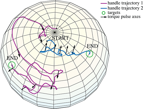
User Study II: Two example orientation trajectories from one user, shown as projections onto a sphere. The axes for the torque pulses applied are shown as arrows. In one, the user follows a relatively direct path to the target. In the other, the user does not respond correctly to the torque pulses and follows a more meandering path to the target.
The median time taken for users to reach the specified target was 8.63 s (mean = 11.54 s, standard deviation = 10.92 s). When projected onto a unit sphere, each trajectory’s path length can be compared to the direct path to each target. The median ratio of path lengths to direct path lengths was 3.31 (mean = 4.32, standard deviation = 3.73). There was not a significant difference in mean trial time as users completed more trials. Performance varied by target - the angle down from vertical and the quadrant each target was located in affected the difficulty of reaching it. Quadrants are defined in Fig. 9 as left, front, right, and back.
6.3.1. Trial Time
A two-way repeated measures ANOVA revealed a significant effect on trial time for both the quadrant (F = 4.496, p < 0.01) and the magnitude of the angle from vertical to the target (F = 14.880, p < 10−6). Post-hoc multiple comparison tests on the target quadrant revealed significant differences only between targets in the front and back quadrants (Fig. 11(a)). Targets toward the front took an average of 3.55 seconds longer to reach than those toward the back (p < 0.01). A post-hoc linear mixed-effects model was generated relating target times to angle from vertical with subject included as a random effect. As is evident in Fig. 12(a), effect of angle is significant, estimated as 0.257 s/° (p < 10−7). The specific targets with the longest mean trial times were the targets furthest forward and furthest to the right (72° from vertical).
Fig. 11.
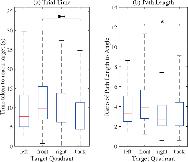
User Study II: (a) Time to reach targets in each quadrant. (b) Path length to reach targets in each quadrant scaled by magnitude of angle to the target. The front quadrant targets had the longest average trial times and scaled path lengths. For figure clarity, outliers are not shown.
Fig. 12.
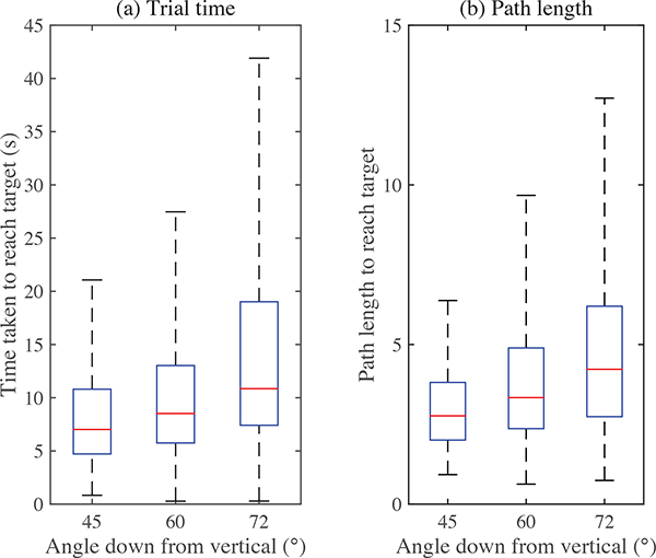
User Study II: (a) The time to reach targets increased with their distance from the starting vertical position. (b) The path length also increased as target distance increased. The effect of angle is significant for both time and path length (p < 10−7). For figure clarity, outliers are not shown.
6.3.2. Path Length
Similar effects were seen between quadrants with regards to path length. A two-way repeated measures ANOVA on path lengths with quadrant and target distance as variables revealed significant effects for both the quadrant (F(3,12) = 3.318, p < 0.05) and the angle magnitude to the target (F(2,12) = 14.603, p < 10−6). A post-hoc multiple comparison test on the effect of quadrant showed significant differences only between front and back quadrants (p < 0.05), shown in Fig. 11(b), in which the path length is normalized by the magnitude of the angle to the target. A post-hoc linear mixed-effects model with subject included as a random effect estimated that the ratio of path length to target angle increases by 0.093 for each additional degree to the target (p < 10−7). This relationship is evident in Fig. 12(b).
6.3.3. Initial Direction
When users were holding the device vertically at the start of each trial, the cues given were similar to what they experienced in the first user study, except they could be oriented in any direction rather than just orthogonal directions. Users responded by tilting toward the cued direction rather than selecting it on the keyboard. As an analog to the first study, Fig. 13 shows the errors in the users’ initial directions of motion, defined as the difference in longitude between the device handle and the intended target when the handle first crosses an angle of 40° down from vertical. There are peaks near 0° and 180°. Users were often able to identify and move in approximately the direction indicated by the device. However, in a large number of trials, users moved in the opposite direction.
Fig. 13.
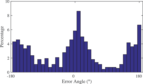
User Study II: The error in users’ initial direction of motion: the angle between the place where the handle orientation first passes 40° from vertical and the correct angle to the target. In most trials users rotated toward the target, but in many trials they first rotated away from the target (180° of error).
6.3.4. Responses to Torque Cues
Torque cues were always directed toward the target, and there was a roughly even distribution of torque directions cued, with a mean angle relative to the handle’s x axis of 7.67° (pushing users to rotate toward the back and slightly right). We define error responding to torque cues as the angle between the direction the torque cue intends the user to rotate and the direction of the user’s rotation by the start of the next torque cue.
The users’ error responding to cues across different regions of the workspace and in response to different directions is shown in Fig. 14. A separate histogram for each torque direction is provided in each quadrant. Each histogram shows the percentage of that subset of cues with different magnitudes of error. Histograms with peaks near 0° of error correspond to better performance, whereas histograms with peaks near 180° correspond to poor performances.
Fig. 14.
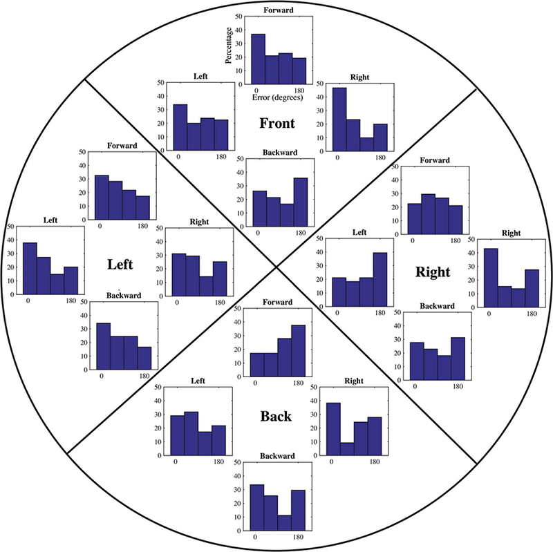
User Study II: The magnitude of the error responding to each torque pulse, separated by quadrant and by direction of torque pulse. Torque directions include data for all torque cues within 45° of orthogonal direction (left, front, right, and back).
6.4. Discussion
All users were able to reach every target in the experiment with the device’s guidance. This study showed that there is potential for asymmetric torque pulses to provide ungrounded kinesthetic guidance. Users reported in postexperiment surveys that they felt they were actually being pushed toward targets by the device. When asked about their strategy, some users said they held the device loosely and let it move their hands for them. Here we discuss the variation in trial time and path lengths among different target locations, the trends in users’ responses to each torque cues, and opportunities for improvement in pulse frequency and magnitude.
6.4.1. Target Location
Unsurprisingly, targets that were farther from the starting vertical orientation took longer to reach and had longer path lengths than closer targets did (Fig. 12). Because users tended to move only a small amount in response to each torque pulse, more pulses were necessary to guide them through larger rotations. Users also noted in postexperiment surveys that the farthest targets were approaching the limits of their wrist rotations, making it more difficult to make precise movements in response to the cues.
This task required mainly pronation and supination of the forearm and radial and ulnar deviation of the wrist. The range of motion for pronation and supination is close to 90° in each direction [24]. For most daily activities, the wrist stays within 40° of ulnar deviation and 17° of radial deviation [25], so the rotations in this study required larger angles than typical motion. Users’ elbows were not restricted, so they were able to reach targets at larger angles by pivoting or moving their elbows. The torque device provides cues strong enough to push the hand through the correct rotation if there is little impedance by the hand. However, in areas of the workspace where wrist motion is more difficult, the device cannot move the hand on its own. In these areas, it is more dependent on the user to interpret the direction of the cue and move accordingly or to realign the elbow or hand to reduce the impedance.
Users identified cues toward the back as more difficult than cues toward the front in the first study. Surprisingly, in the second study targets toward the front quadrant took significantly longer than targets in the back quadrant and had significantly longer path lengths. Depending on arm length and posture, users may have had to lift their elbows off the arm-rest to reach the farthest forward targets. If they did not realize the pulses were directing them farther than their wrist rotation, this range of motion limitation may have slowed them down. For targets toward the back, left, and right, they may have only had to pivot on their elbow. A task in truly free space, with no elbow rest may not exhibit this difference. Alternatively, a task that incorporates more flexion and extension than radial and ulnar deviation could be more suitable because of the larger ranges of motion.
6.4.2. Response to Guidance
It was difficult for users to correctly respond to small adjustments in orientation. Experiments in [19] found that the human threshold for differentiating the angle of forces is approximately 15°, so we might have expected similar errors here. Because of the asymmetric nature of the pulses, errors were often actually near 180°. Motion in response to cues was more prone to error in some regions of the workspace than others. The orientation of the handle had a strong influence on how easy it was to perceive and respond to the torque pulses. In post-experiment surveys, users reported that it was easier to tell which direction they were being pushed when holding the device vertically. Some users even returned the device to vertical mid-trial when they felt confused about the cues.
Effects of Quadrant:
Fig. 14 shows the error in response to torque cues in different directions when the handle orientation is in each quadrant of the workspace. In the left and front quadrants, seven of the eight histograms show the highest percentage error is near 0°, corresponding to better performance. In the right and back quadrants, only three of the eight histograms have a largest percentage of error near 0°, and many of them have peaks near 180° off from the correct direction. The errors are distributed differently for different torque directions. Fig. 14 shows that cues toward the back had the highest percentages of errors close to 180°. Counter to our expectations from the first study, cues toward the right had the smallest errors except when the hand was rotated into the left quadrant. Humans have a larger range of motion for ulnar deviation (tilting forward) than radial deviation (tilting backward) [24]. This combined with the sparser distribution of mechanoreceptors in the palm and wrist than the fingers [21] could account for poorer performance when the device is in the back or right quadrant and primarily contacts the palm.
For all quadrants, performance responding to torque cues away from the current quadrant was poor (shown by the inner four histograms in Fig. 14). In these cases, most responses were near 180° off, except in the left quadrant where it was more even. The opposite case, where the cue is in the direction of the current quadrant had good performance (shown by the outermost histograms in Fig. 14). It is possible that once users believed the cues were pushing them one way and rotated toward that quadrant, they were resistant to cues directing them against this initial belief. Additionally, although the device is light, when it is tilted, the torque due to the weight of the motors at the top may detract from the applied cues. The magnitude of the torque due to gravity is approximately 10 N-mm when tilted at a 45° angle, and approximately 18 N-mm when tilted at a 60° angle. At large tilt angles, this effect may reduce the upward torque cues by almost half. One way to address this could be to redesign the device such that the center of mass is located where the user grips the device, rather than above the hand.
Initial Motion:
It is clear from Fig. 13 that users often chose the entirely opposite direction when beginning trials. Although the asymmetric pulses are almost four times stronger in one direction than the other, there is no net torque on the user’s hand. This is a limitation for any ungrounded kinesthetic device. Users can overcome any rotation generated by the strong pulses if they interpret the direction incorrectly. Users may respond to the weaker resetting pulse rather than the strong pulse if motion in the direction of the strong pulse is difficult or uncomfortable, or if perception in that part of the hand is poorer.
Further research is necessary to understand the effect of direction and orientation on a user’s ability to identify and respond to asymmetric torque cues. We should design ungrounded guidance to better accommodate for effects of torque direction and wrist kinematics on a user’s likelihood of correctly perceiving and responding to a torque guidance cue. The guidance cues provided in this study were always directly toward the target. For some targets, a more successful trajectory might avoid torque directions that are known to be error-prone or avoid areas of the workspace where it is more difficult for a user to maneuver.
6.4.3. Pulse Timing and Magnitude
The pulse frequency and pulse width of the strong torque cue were selected based on pilot testing and torque measurements to maximize the asymmetry between the forward and reverse pulses. Too short a pulse width exceeds the gimbal motors’ trajectory-tracking capabilities, but longer pulse widths reduce the asymmetry. The low frequency selected provided for acceptable tracking as well as a slow, low-magnitude return pulse. Using a low frequency also gave users time to respond to each strong cue, allowing us to study differences in their motion between cues in different directions. However, there are many reasons a higher frequency might be desirable. It may have enabled users to reach the targets more quickly and the pulses could feel smoother to the user. Future studies with this kind of system should tune the pulse widths and frequencies applied based on user performance and preference.
In this experiment, we varied only the direction of the torque cues, but the magnitude could be varied as well. A natural extension would be to scale the magnitude proportional to the error. We found in preliminary testing that the direction of cues became less clear at lower magnitudes, and performance was not improved by proportional feedback. If future iterations of the device are capable of higher torques, it may become feasible to include proportional feedback.
7. Conclusion
We presented a small, hand-held, dual-CMG device for providing ungrounded, kinesthetic torque cues. By taking advantage of CMG dynamics and rotating a second, counter-spinning CMG opposite the first one, a single torque axis can be isolated, providing kinesthetic haptic cues to a user. We verified the torque isolation with measurements of the pulses produced by our device. Although only a brief high-torque pulse can be generated, the device can cause directed motion like a traditional kinesthetic haptic device by applying repeated, low-frequency asymmetric pulses.
We investigated the performance of this haptic device through two user studies. In the first study, users identified the direction that the device was rotating their hand (left, right, back, front, clockwise, or counterclockwise). They were able to identify the direction correctly in almost every trial. In the second study, we provided tilting cues to users in a closed-loop manner, based on error from a target handle orientation. Users were able to successfully reach the target orientation in every trial. Movement in response to torque cues varied with hand orientation and cue direction. Future work may explore ways of optimizing the frequency and asymmetry of the pulses and planning torque cues to account for variations in workspace and direction.
Any ungrounded haptic feedback device is somewhat dependent on users’ interpretation and response because it cannot provide a continuous net torque or force to direct them to a target orientation or position. This device is able to provide guidance with less interpretation than previously developed ungrounded haptic devices because the strong torque pulses generate motion of the hand without input. Due to the second counter-spinning CMG, this device can generate clearer torque signals than previous CMG-based haptic devices, with a lighter, more compact form.
A system like this one could be used to provide feedback for object interactions and guidance in virtual environments, pointing or aiming adjustments in alignment tasks, guidance for sports equipment such as a tennis racket, or portable guidance in large environments like pedestrian navigation. In situations where grounded haptic cues are not practical, a dual-CMG haptic device could provide an effective solution.
Acknowledgments
The authors would like to thank Philipp Stolka and Alex Mallery for their assistance developing this system.
*This work was supported in part by a National Science Foundation Graduate Fellowship, a Stanford Graduate Fellowship, and National Institutes of Health Grant R44CA168127.
Biography

Julie M. Walker received a B.S. degree from Rice University, Houston TX in 2014 and an M.S. degree from Stanford University, Stanford, CA in 2016, both in mechanical engineering. She is currently a Ph.D. candidate in the mechanical engineering department at Stanford University working in the CHARM Laboratory. Her research interests include haptics, virtual environments, teleoperation, and medical devices.

Heather Culbertson is a postdoctoral fellow in mechanical engineering at Stanford University. She received her PhD in the department of mechanical engineering and applied mechanics (MEAM) at the University of Pennsylvania in 2015 working in the Haptics Group, a part of the GRASP Laboratory. She completed a Masters in MEAM at the University of Pennsylvania in May of 2013, and she earned a B.S. degree in mechanical engineering at the University of Nevada, Reno in 2010.

Michael Raitor is an undergraduate studying mechanical engineering at Stanford University, Stanford, CA. His research interests include medical devices, haptics, teleoperation, neuromechanics and rehabilitation, prosthetics, bioinspired materials, soft exoskeletons, and engineering education.

Allison M. Okamura received the B.S. degree from the University of California, Berkeley, in 1994, and the M.S. and Ph.D. degrees from Stanford University, Stanford, CA, in 1996 and 2000, respectively, all in mechanical engineering. She is currently a Professor of mechanical engineering at Stanford University, Stanford, CA. Her research interests include haptics, teleoperation, medical robotics, virtual environments and simulation, neuromechanics and rehabilitation, prosthetics, and engineering education.
References
- [1].Alahakone AU and Senanayake SMNA, “Vibrotactile Feedback Systems: Current Trends in Rehabilitation, Sports and Information Display,” in IEEE/ASME International Conference on Advanced Intelligent Mechatronics, 2009, pp. 1148–1153. [Google Scholar]
- [2].Pacchierotti C, Prattichizzo D, and Kuchenbecker KJ, “Displaying Sensed Tactile Cues with a Fingertip Haptic Device,” IEEE Transactions On Haptics, vol. 8, no. 4, pp. 384–396, 2015. [DOI] [PubMed] [Google Scholar]
- [3].Quek ZF, Schorr SB, Nisky I, Provancher WR, and Oka-mura AM, “Sensory Substitution and Augmentation Using 3-Degree-of-Freedom Skin Deformation Feedback,” IEEE Transactions On Haptics, vol. 8, no. 2, pp. 209–221, 2015. [DOI] [PubMed] [Google Scholar]
- [4].Spiers A, Dollar A, van der Linden J, and Oshodi M, “First validation of the haptic sandwich: A shape changing handheld haptic navigation aid,” in International Conference on Advanced Robotics, July 2015, pp. 144–151. [Google Scholar]
- [5].Wagner CR and Howe RD, “Mechanisms of performance enhancement with force feedback,” in IEEE World Haptics Conference, 2005, pp. 21–29. [Google Scholar]
- [6].Prattichizzo D, Chinello F, Pacchierotti C, and Malvezzi M, “Towards wearability in fingertip haptics: A 3-DoF wearable device for cutaneous force feedback,” IEEE Transactions on Haptics, vol. 6, no. 4, pp. 506–516, 2013. [DOI] [PubMed] [Google Scholar]
- [7].He PC and Jingxian, “Steering Law for Two Parallel Variable-Speed Double-Gimbal Control Moment Gyros,” Journal of Guidance, Control, and Dynamics, vol. 37, no. 1, pp. 350–359, 2014. [Google Scholar]
- [8].Steyn D, “Variable Speed Scissored Pair Dual Gimbal Control Moment Gyro for Nano-Sattelites,” Ph.D. dissertation, Stellenbosch University, 2015. [Google Scholar]
- [9].Amemiya T and Gomi H, “Directional torque perception with brief, asymmetric net rotation of a flywheel.” IEEE Transactions on Haptics, vol. 6, no. 3, pp. 370–5, 2013. [DOI] [PubMed] [Google Scholar]
- [10].Tanaka Y, Masataka S, Yuka K, Fukui Y, Yamashita J, and Nakamura N, “Mobile torque display and haptic characteristics of human palm,” in International Conference on Artificial Reality and Telexistence, 2001, pp. 115–120. [Google Scholar]
- [11].Sakai M, Fukui Y, and Nakamura N, “Effective Output Patterns for Torque Display “GyroCube”,” in International Conference on Artificial Reality and Telexistence, 2003, pp. 1–6. [Google Scholar]
- [12].Choiniere J-P and Gosselin C, “Development and experimental validation of a haptic compass based on asymmetric torque stimuli,” IEEE transactions on haptics, vol. 10, no. 1, pp. 29–39. [DOI] [PubMed] [Google Scholar]
- [13].Winfree KN, Romano JM, Gewirtz J, and Kuchenbecker KJ, “Control of a high fidelity ungrounded torque feedback device: The iTorqU 2.1,” IEEE International Conference on Robotics and Automation, pp. 1347–1352, 2010. [Google Scholar]
- [14].Murer M, Maurer B, Huber H, Aslan I, and Tscheligi M, “TorqueScreen : Actuated Flywheels for Ungrounded Kinesthetic Feedback in Handheld Devices,” in International Conference on Tangible, Embedded, and Embodied Interaction, 2015, pp. 161–164. [Google Scholar]
- [15].Antolini M, Bordegoni M, and Cugini U, “A haptic direction indicator using the gyro effect,” in IEEE World Haptics Conference, 2011, pp. 251–256. [Google Scholar]
- [16].Antolini M, “The Use of Haptic Devices to Convey Directional Information,” Ph.D. dissertation, Politecnico Di Milano, 2012. [Google Scholar]
- [17].Chiu J and Goswami A, “Design of a Wearable Scissored-Pair Control Moment Gyroscope (SP-CMG) For Human Balance Assist,” in ASME Int. Design Engineering Technical Conference & Computers and Information in Engineering Conference, 2014, pp. 1–10. [Google Scholar]
- [18].Walker JM, Raitor M, Mallery A, Culbertson H, Stolka P, and Okamura AM, “A Dual-Flywheel Ungrounded Haptic Feedback System Provides Single-Axis Moment Pulses for Clear Direction Signals,” in IEEE Haptics Symposium, 2016, pp. 7–13. [Google Scholar]
- [19].Elhajj I, Weerasinghe H, Dika A, and Hansen R, “Human perception of haptic force direction,” in IEEE International Conference on Intelligent Robots and Systems, 2006, pp. 989–993. [Google Scholar]
- [20].Jandura L and Srinivasan MA, “Experiments on Human Performance in Torque Discrimination And Control,” Dynamic Systems and Control, vol. 55, no. 1, pp. 369–375,1994. [Google Scholar]
- [21].Vallbo AB and Johansson RS, “Properties of cutaneous mechanoreceptors in the human hand related to touch sensation.” Human Neurobiology, vol. 3, no. 1, pp. 3–14,1984. [PubMed] [Google Scholar]
- [22].Gregorio MD and Santos VJ, “Precision grip responses to unexpected rotational perturbations scale with axis of rotation,” Journal of Biomechanics, vol. 46, no. 6, pp. 1098–1103, 2013. [DOI] [PubMed] [Google Scholar]
- [23].Rinderknecht MD, Popp WL, Lambercy O, and Gassert R, “Reliable and Rapid Robotic Assessment of Wrist Proprioception Using a Gauge Position Matching Paradigm,” Frontiers in Human Neuroscience, vol. 10, pp. 1–12, 2016. [DOI] [PMC free article] [PubMed] [Google Scholar]
- [24].Kane PM, Vopat BG, Akelman E, Got C, and Mansuripur K, “The Effect of Supination and Pronation on Wrist Range of Motion,” Journal of Wrist Surgery, vol. 3, no. 3, pp. 187–191, 2014. [DOI] [PMC free article] [PubMed] [Google Scholar]
- [25].Ryu J, Iii WPC, Askew LJ, An K, and Chao EYS, “Functional ranges of motion of the wrist joint,” Journal of Hand Surgery, pp. 409–419, 1991. [DOI] [PubMed] [Google Scholar]


