

Abstract
Background:
In anatomic anterior cruciate ligament (ACL) reconstructions produced with flexible reamers and no knee hyperflexion, it is unknown whether knee hyperflexion is necessary for femoral interference screw insertion.
Purpose:
To compare femoral screw-graft divergence in anatomic ACL reconstructions with endoscopic interference screws placed without knee hyperflexion and with the use of flexible versus rigid screwdrivers.
Study Design:
Controlled laboratory study.
Methods:
Ten matched pairs of cadaveric knees had bone-tendon-bone graft ACL reconstructions with anatomic femoral tunnels. The knees were flexed to 90°. Femoral interference screws (7 × 20 mm) were placed in pairs of knees: in 1 knee with a flexible screwdriver and in the opposite knee with a rigid screwdriver. Graft-screw divergence was imaged with computed tomography scans and tested with cyclic and static biomechanical tests.
Results:
The mean screw-graft divergence was 12.07° ± 4.04° with the rigid screwdriver and 10.68° ± 3.23° with the flexible screwdriver (P = .35). The cyclic tests with screws placed by a rigid screwdriver had a mean increase in displacement of 0.56 ± 0.20 mm. For screws placed with the flexible screwdriver, the mean increase in displacement was 0.58 ± 0.32 mm (P = .66). Yield load was 393.3 ± 95.1 N for screws placed by a rigid screwdriver and 408.2 ± 119.0 N for screws inserted with the flexible screwdriver (P = .78). Maximum load was 523.1 ± 88.7 N for screws placed by a rigid screwdriver and 467.1 ± 107.3 N for screws inserted with the flexible screwdriver (P = .09).
Conclusion:
With either a rigid or a flexible screwdriver, there were no significant effects on screw divergence or fixation strength.
Clinical Relevance:
Knees can be kept at 90° during endoscopic femoral interference screw insertion. The use of a traditional rigid or flexible screwdriver will not affect screw-graft divergence or fixation strength.
Keywords: interference screw, fixation, divergence, anterior cruciate ligament, ACL
The progression to the use of anatomic femoral tunnels in anterior cruciate ligament (ACL) reconstruction has necessitated new drilling options.10,11,23 Current surgical techniques for creating anatomic femoral tunnels without knee hyperflexion have included custom reamers drilled outside-in or flexible reamers drilled through the anteromedial portal.5,23 Traditional rigid reamers placed through the anteromedial portal have required knee hyperflexion.4,10 The challenge to the surgeon is that, with knee hyperflexion, the view of the notch diminishes with flexion and the femoral footprint is more difficult to determine.22,23 If a repeatable orientation of 90° of flexion is used, the reproducibility of femoral tunnel placement is improved.5,13 Traditional transtibial drilling has become less common, as it tends to place femoral tunnels high in the notch outside the femoral footprint.1,9,18
Coincident with the evolution to anatomic femoral tunnel placement has been the challenge of graft fixation. A popular method for bone-tendon-bone (BTB) graft fixation has been the placement of interference screws retrograde or endoscopically to secure the bone plug in the femoral tunnel.3,10 However, divergence between the screw and the bone plug in the femoral tunnel can diminish fixation strength.6,9,13,15,19 In laboratory tests, divergence between the screw and bone plug of 20° has been necessary to diminished fixation strength.6,9,13,19 For transtibial drilling, multiple strategies have evolved to limit screw-graft divergence, including hyperflexion of the knee during screw insertion.2,7,11,16,18,20 There has been less research on limiting divergence with anatomic femoral tunnels.4
One study of divergence for endoscopically placed interference screws with anatomic femoral tunnels required knee hyperflexion for screw insertion. Lines were placed with a marking pen on the thigh to guide screw insertion, and minimal divergence was reported.4 However, no strength of fixation was measured.4
The purpose of the current study was to compare screw-graft divergence in cadaveric ACL reconstructions with anatomic femoral tunnels with a flexible or rigid screwdriver to place endoscopic interference screws without knee hyperflexion. The flexible screwdriver would conceptually place interference screws collinear with an anatomic tunnel produced with flexible reamers. Divergence and graft fixation strength were compared. The hypothesis was that a flexible screwdriver would place interference screws with less divergence and thus greater strength of fixation.
Methods
Ten pairs (20 knees) of fresh-frozen cadaveric knees were used for testing (Biogift Anatomical). The knees came from 8 male donors and 2 female donors (mean ± SD age, 66.5 ± 3.7 years; range, 26-87 years). Also, 10 pairs of presized patellar tendon allografts (Tissue Bank International) were used for testing. The prepared BTB allografts had been prepared to pass through a 10-mm tunnel and had been terminally sterilized with low-dose radiation.
Specimen Preparation
Knees were thawed for 24 hours at room temperature prior to simulated surgery. The femur was clamped and the tibia flexed to create 90° of knee flexion. The angle of flexion was verified with a goniometer, and it remained constant throughout the ACL reconstruction. All knees had an anatomic femoral tunnel produced with flexible reamers. A lateral portal in the soft spot of the femoral condyle, tibial plateau, and patellar tendon was used for arthroscopic viewing. A standard medial working portal was placed slightly superior to the medial meniscus but not far medial, to avoid damage to the medial condyle during reaming. No knees were judged to have more than minimal partial-thickness articular cartilage degeneration (<1 cm2). A small lateral notchplasty was produced for visualization, and the ACL was completely debrided. A 7-mm offset guide (Stryker) was introduced through the medial portal and raised 8.5 mm above (aimer width, 4 mm) the low point of the articular cartilage to identify a point close to the center of the ACL femoral insertion.5 This method was documented to locate the anatomic center of the femoral ACL attachment.5 An awl was used to create a starter hole at this point. A blue-handle curved aimer (Stryker) for the flexible guide pin (2.2 mm) was introduced through the medial portal, positioned with its tip in the starter hole, and directed to have the pin exit the lateral thigh proximal to the lateral epicondyle. The flexible pin was drilled through the femur and lateral thigh under power to create an anatomic femoral tunnel.23
The femoral tunnel was reamed to a depth of 35 mm through the anteromedial portal with a 10-mm cannulated flexible reamer (Figure 1) placed over a 2.2-mm flexible pin (VersiTomic system; Stryker). For the tibial tunnel, an anteromedial incision and a drill guide were used to place a rigid pin (2.4 mm) to the midmedial ACL tibial attachment. Residual fibers of the ACL were used as a guide for tibial pin placement. The tibial drill guide was set 7° more than the distance between the bone plugs of the patellar graft to prevent graft tunnel mismatch.14 A rigid 10-mm reamer was used to create the tibial tunnel. The grafts had 25-mm bone plugs on each end that would pass through a 10-mm tube. One No. 5 Ethibond suture (Ethicon) was placed through a drill hole in the patellar plug, and two No. 5 Ethibond sutures were placed through separate drill holes in the tibial plug. With the patellar plug suture, the graft was pulled through the tibial tunnel into the femoral tunnel to have the patellar bone plug sit flush with the lateral notch. Grafts were positioned to have the cancellous surface of the bone plugs facing anterior and superior (Figure 2). Pairs of knees were sequentially alternated between right and left for placement of a femoral interference screw with either a rigid screwdriver or a flexible screwdriver (Figure 3). The femoral bone plug suture was removed after screw insertion.
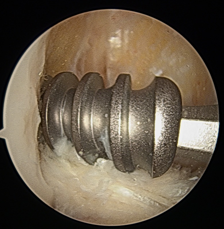
Figure 1.

Flexible reamer with jigsaw design used to ream anatomic femoral tunnel through anteromedial portal.
Figure 2.

A guide pin placed anterior and superior to cancellous surface of the bone block.
Figure 3.
An interference screw is placed with a rigid or flexible screwdriver as directed by the guide pin.
Femoral Fixation With Rigid Screwdriver
The knee was kept at 90° of knee, and a 1.5-mm guide pin was placed manually through the anteromedial portal under arthroscopic view to lie anterior to the cancellous surface of the bone plug and to the depth of the femoral tunnel. A rigid screwdriver was used to advance a 7 × 20–mm titanium metal interference screw (Stryker), leaving the screw base flush with the lateral notch. The screwdriver was not manipulated to direct the screw other than to have the screw follow the path of the guide wire.
Femoral Fixation With Flexible Screwdriver
The knee was kept at 90° of flexion, and with a guide, a flexible pin was introduced through the anteromedial portal and placed anterior to the cancellous surface of the bone plug and to the depth of the femoral tunnel. A flexible screwdriver with a jigsaw design (Figure 4) was used through the anteromedial portal to advance a 7 × 20–mm titanium metal interference screw (Stryker) to leave its base flush with the lateral notch.
Figure 4.

A flexible screwdriver with jigsaw segmentation.
Tibial Fixation
After femoral interference screw insertion with a flexible or rigid screwdriver, the same tibial fixation was conducted on all knees. The knee was placed in 30° of flexion; an estimated 45 N (10 lb) of tension was placed on the sutures of the tibial plug; and a 9 × 25–mm titanium metal interference screw was placed in the tibial tunnel with a rigid screwdriver over a guide wire to secure the tibial plug of the graft. To back up the fixation on the tibial side, the sutures in the tibial plug were tied around a 6.5 × 35–mm cancellous screw and a washer placed distal to the interference screw. Knees were refrozen after the ACL reconstruction.
Computed Tomography Scan Analysis
The frozen knees were transported to a commercial computed tomography (CT) scan facility, where images were obtained with a Siemens Somatom Sensation 10 CT scanner with a standard knee protocol for data acquisition. The knees were placed in full extension, and images were obtained with a slice thickness of 0.75 mm and a detector size of 512 × 512. Subsequently, with custom imaging software, the femoral tunnel was segmented out from the surrounding bone tissue (ScanIP, v 6.0; Simpleware Ltd), and the resulting geometry was imported into 3-dimensional model processing software (Geomagic 2013; 3D Systems) (Figure 5). A best-fit cylinder was generated through the tunnel to determine the center axis line of the bone tunnel. With the same methods, the screw was segmented and reconstructed from the same set of CT scans. The tunnel and screw axes were imported into CAD (computer-aided design) software (Creo Elements / Pro, v 5.0; PTC), and the angle between the screw and tunnel was measured. While the orthogonal coordinates were maintained, the CAD software measured the screw-tunnel divergence angle with a custom plane that maximized the screw-tunnel divergence.
Figure 5.

(A) From the 0.75-mm-slice computed tomography scans, the tunnel (plus graft) was reconstructed. Using a geometric program, the computer generated a best-fit cylinder from the model. The arrow points to the axis line of the cylinder. (B) From the same set of computed tomography scans, the screw was reconstructed. Using a geometric program, the computer generated an axis of the screw (green line). Both axes were imported into Geomagic 2013 (3D Systems), and the software measured the angle created by the 2 axes.
Biomechanical Testing
Specimens were thawed for 24 hours at room temperature prior to testing. The tibiofemoral joints were dissected of all soft tissue to leave the femur, BTB graft, tibia, and graft fixation intact. The distal femur and proximal tibia were secured to custom jigs with adhesive (Smooth-Cast 300; Smooth-On Inc) (Figure 6).
Figure 6.

A left knee is shown as secured before mechanical testing. The femur and tibia were secured to custom jigs incorporating adhesive. The knees were positioned in extension.
The knees were positioned in full extension with the jigs attached to an Instron 8511 testing machine (Figure 6). Tests were performed by vertical distraction of the joint with a cyclic loading profile. For cyclic tests, an initial preload of 50 N was applied for 1 minute, followed by loading between 50 and 150 N at a frequency of 1 Hz. With a high-resolution digital camera (PL-B681C; PixeLINK), displacements were recorded between markers placed on specimens (Figure 7).
Figure 7.

A right knee is shown with 2 marks on the posterior femoral condyles and tibial plateau. A digital camera recorded displacements between these marks during mechanical testing.
Displacements between the markers were calculated after 50, 100, 150, 200, and 250 cycles via a code developed in-house (Matlab; MathWorks Inc). Load-to-failure tests were then performed at a rate of 1.0 mm/s. Yield load was the point on the load-displacement curve where load first diminished. Stiffness was the slope in the linear region of the load-displacement curve between 20% and 60% of yield load. Maximum load was the highest load in the load-displacement curve, where the mode of failure was recorded (Figure 8).
Figure 8.

A left knee is shown after testing to failure. The tibial bone plug has fractured and displaced from the tibial interference screw, indicating tibial failure.
Statistical Analysis
A power analysis was performed according to the data published by Bedi et al1 on the coronal angle of femoral tunnels drilled either obliquely or vertically with the transtibial method. With standard deviations ranging from 12% to 13%, a sample size of 6 was sufficient to provide a power of 0.99 for this study.
The distribution of the data set was assessed for normality via the Shapiro-Wilk test. Paired Student t tests were used to compare yield load, ultimate load, failure load, stiffness, and imaging divergence angles. A 2-way analysis of variance, with cycle and group as independent variables, was used to examine differences between cycles across the groups. Fisher exact test for 2 × 2 contingency tables was used to assess differences in failure mode.
All data analysis was performed with SPSS (v 19.0; IBM). All comparisons were considered 2-tailed, and a P value <.05 characterized statistical significance.
Results
Radiographic Screw-Tunnel Divergence
The vector of the femoral tunnel could not be identified on both knees for 5 pairs of anterior-posterior images, 8 pairs of lateral images, and 5 pairs of tunnel images. This provided only 12 paired measurements from radiographs. The overall screw-tunnel divergence with these radiographs was 10.2° ± 5.7° with a rigid screwdriver and 9.3° ± 6.0° with a flexible screwdriver. This difference was not significant (P = .38).
CT Imaging of Screw-Tunnel Divergence
All screws and tunnels were imaged with CT scanning, and screw-tunnel divergence was measured. The maximum divergence per CT analysis was 12.07° ± 4.04° with the rigid screw driver and 10.68° ± 3.23 with the flexible screw driver (Table 1). This difference was not statistically significant (P = .35).
TABLE 1.
Screw-Tunnel Divergence Measured With Computed Tomography Scan
| Screwdriver | ||
|---|---|---|
| Rigid (n = 10) | Flexible (n = 10) | |
| Divergence, mm | ||
| Mean ± SD | 12.07 ± 4.04 | 10.68 ± 3.23 |
| Range | 5.62-18.32 | 7.22-14.90 |
Biomechanical Testing
Data acquisition was not available for 1 pair of knees; therefore, biomechanical data are reported for 9 paired specimens.
Cyclic Displacement
There was minimal residual femoral-tibial displacement (<0.10 mm) for knees with screws placed with either screwdriver up to 250 cycles and 150-N load. After 250 cycles, the knees with screws placed by a rigid screwdriver had a mean increase in femoral-tibial displacement of 0.56 ± 0.20 mm. The same measurement for the knees with screws inserted with the flexible screwdriver was 0.58 ± 0.32 mm. The difference was not statistically significant (P = .66).
Load-to-Failure Tests
Results for the load-to-failure tests are listed in Table 2. There were no statistically significant differences between the flexible versus rigid screwdriver with regard to yield load, displacement to yield load, stiffness, or maximum load. The mode of failure for the rigid screwdriver specimens included 3 femoral sides and 7 tibial sides and, for the flexible screwdriver, 5 each.
TABLE 2.
Load-to-Failure Biomechanical Tests
| Screwdriver | |||
|---|---|---|---|
| Rigid (n = 9) | Flexible (n = 9) | P Value | |
| Yield load, N | |||
| Mean ± SD | 393.3 ± 95.1 | 408.2 ± 119.0 | .78 |
| Range | 229.4-560.2 | 260.0-662.7 | |
| Displacement to yield load, mm | |||
| Mean ± SD | 9.10 ± 2.4 | 7.83 ± 3.3 | .23 |
| Range | 4.3-12.2 | 4.5-10.1 | |
| Stiffness, N/mm | |||
| Mean ± SD | 75.7 ± 32.9 | 67.1 ± 33.3 | .43 |
| Range | 33.8-149.8 | 60.5-129.5 | |
| Maximum load, N | |||
| Mean ± SD | 523.1 ± 88.7 | 467.1 ± 107.3 | .09 |
| Range | 365.9-643.7 | 349.0-602.0 | |
Discussion
The important finding of this study was that knee hyperflexion was not necessary during endoscopic interference screw insertion with a rigid or flexible screwdriver. Placing the knee in hyperflexion increases the risk of medial condyle injury during reaming and distorts the view of the notch. The use of a flexible reamer obviates the need for hyperflexion.23 The hypothesis was rejected because the flexible screwdriver provided negligible differences in divergence and fixation strength. For both types of screwdrivers, the screws were placed over a guide wire that was placed anterior to the cancellous surface of the bone plug. Presumably, the interference screw followed the path of the guide wire more than being directed by the type of screwdriver. The practical implication is that knees can be left in 90° of flexion throughout endoscopic screw insertion regardless of screwdriver type with anatomic femoral tunnels. The findings of this study may be specific to the type of screwdrivers, screws, and guide wires used or to the surgeon performing the procedure.4 We speculate that the placement of the guide wire clearly anterior to the bone plug was critical.
Anatomic femoral tunnels have an obliquity different from that of transtibially drilled femoral tunnels, and it would be expected that possibly greater hyperflexion would be necessary than for a traditional femoral tunnel to prevent divergence.17 Again, this was not the finding of the study, and knees can remain at 90° throughout screw insertion.
Prior studies of screw-graft divergence used tunnel alignment to estimate bone plug position because imaging of bone plugs within tunnels has been challenging.12,16 The present study found standard radiographic imaging of tunnels to be inconsistent, and the technology of the CT scan was necessary to evaluate alignment. CT technology allowed measurement of the greatest divergence present, in contrast to radiographs, which measure divergence within 3 specific planes.
The static fixation strength measurements to failure were generally consistent with tests of older cadaveric specimens tested to failure.3,21 The mode of failure was similar for screws placed with either the rigid or the flexible screwdriver. The cyclic tests to 150-N load were well below the yield load for all specimens, and very little displacement of the femur-graft-tibia complexes was documented. Cyclic tests have required loads of 250 N to demonstrate fixation failure in laboratory testing.13,15 The lower load of 150 N was chosen in the present study to preserve knees for static tests to failure. The direction of displacement in the strength tests was vertical distraction in line with the tibia. This was done for consistency of testing conditions. While this alignment has been used in prior tests of fixation strength in human cadaveric knees, it is believed that anterior translation of the tibia will maximize ACL strength.3,9,19,22
Screw-graft divergence with BTB grafts has been assessed in bench tests with porcine and bovine knees and reviewed clinically. Jomha et al9 documented a 22% decrease in fixation strength with porcine knees if screw-graft divergence was 30° as compared with no divergence. Lemos et al12 found no diminished fixation strength with 15° of divergence in bovine knees. Pierz et al19 found that 15° of divergence had no effect on fixation strength in porcine knees, while a divergence of 30° led to a significant reduction in fixation strength. In contrast, multiple clinical studies measured screw-graft divergence of up to 30° with no apparent clinical impact.2,7,8,11,18 Dworsky et al7 speculated that an interference screw placed endoscopically provided a buttress to prevent femoral bone plug motion even if it was divergent. Soft tissue graft fixation with interference screws has been more challenging, with 15° of divergence decreasing fixation strength.6,13
The limitations of this study include the possible surgeon-specific findings. The guide wire was placed anterior to the bone plug in all specimens, and the direction that the screw followed was not constrained. The placement of the anteromedial portal was surgeon specific, which may have influenced the vector of the screwdriver. Also, the study was performed with older cadaveric specimens. Clinically, the strength of the bone would likely be greater in young patients, and this may affect the trajectory of the screw.
Conclusion
The findings of this study support the clinical practice of leaving knees at 90° of flexion for endoscopic interference screw insertion for BTB grafts. When knees were left at 90° of flexion, screwdriver type—rigid or flexible—had no significant effect on screw divergence or fixation strength. Regardless of screwdriver type, screw-graft divergence was <20° and in a range that did not affect fixation strength.
Footnotes
One or more of the authors has declared the following potential conflict of interest or source of funding: Stryker Corp provided the materials and cadaveric knees, imaging tools, and mechanical testing apparatus for this study. M.E.S. receives royalties from Stryker. D.W. has received hospitality payments from Kairos Surgical and Stryker. A.N. has grants pending from the National Institutes of Health and patent pending with the BIDMC.
Ethical approval was not sought for the present study.
References
- 1. Bedi A, Raphael B, Maderazo A, Pavlov H, Williams RJ., 3rd Transtibial versus anteromedial portal drilling for anterior cruciate ligament reconstruction: a cadaveric study of femoral tunnel length and obliquity. Arthroscopy. 2010;26(3):342–350. [DOI] [PubMed] [Google Scholar]
- 2. Brodie JT, Torpey BM, Donald GD, 3rd, Bade HA., 3rd Femoral interference screw placement through the tibial tunnel: a radiographic evaluation of interference screw divergence angles after endoscopic anterior cruciate ligament reconstruction. Arthroscopy. 1996;12(4):435–440. [DOI] [PubMed] [Google Scholar]
- 3. Brown CH, Jr, Hecker AT, Hipp JA, Myers ER, Hayes WC. The biomechanics of interference screw fixation of patellar tendon anterior cruciate ligament grafts. Am J Sports Med. 1993;21(6):880–886. [DOI] [PubMed] [Google Scholar]
- 4. Capo J, Kaplan DJ, Fralinger DJ, et al. Femoral screw divergence via the anteromedial portal using an outside-in retrograde drill in bone–patella tendon–bone anterior cruciate ligament reconstruction: a cadaveric study. Arthroscopy. 2017;33(2):355–361. [DOI] [PubMed] [Google Scholar]
- 5. Davis AD, Manaqibwala MI, Brown CH, Jr, Steiner ME. Height and depth guidelines for anatomic femoral tunnels in anterior cruciate ligament reconstruction: a cadaveric study. Arthroscopy. 2016;32(6):1098–1105. [DOI] [PubMed] [Google Scholar]
- 6. Duffee AR, Brunelli JA, Nyland J, Burden R, Nawab A, Caborn D. Bioabsorbable screw divergence angle, not tunnel preparation method influences soft tissue tendon graft-bone tunnel fixation in healthy bone. Knee Surg Sports Traumatol Arthrosc. 2007;15(1):17–25. [DOI] [PubMed] [Google Scholar]
- 7. Dworsky BD, Jewell BF, Bach BR., Jr Interference screw divergence in endoscopic anterior cruciate ligament reconstruction. Arthroscopy. 1996;12(1):45–49. [DOI] [PubMed] [Google Scholar]
- 8. Fanelli GC, Desai BM, Cummings PD, Hanks GA, Kalenak A. Divergent alignment of the femoral interference screw in single incision endoscopic reconstruction of the anterior cruciate ligament. Contemp Orthop. 1994;28:21–25. [Google Scholar]
- 9. Jomha NM, Raso VJ, Leung P. Effect of varying angles on the pullout strength of interference screw fixation. Arthroscopy. 1993;9(5):580–583. [DOI] [PubMed] [Google Scholar]
- 10. Kurosaka M, Yoshiya S, Andrish JT. A biomechanical comparison of different surgical techniques of graft fixation in anterior cruciate ligament reconstruction. Am J Sports Med. 1987;15(3):225–229. [DOI] [PubMed] [Google Scholar]
- 11. Lemos MJ, Albert J, Simon T, Jackson DW. Radiographic analysis of femoral interference screw placement during ACL reconstruction: endoscopic versus open technique. Arthroscopy. 1993;9(2):154–158. [DOI] [PubMed] [Google Scholar]
- 12. Lemos MJ, Jackson DW, Lee TQ, Simon TM. Assessment of initial fixation of endoscopic interference femoral screws with divergent and parallel placement. Arthroscopy. 1995;11(1):37–41. [DOI] [PubMed] [Google Scholar]
- 13. Miller CM, Tibone JE, Hewitt M, Kharrazi FD, Elattrache NS. Interference screw divergence in femoral tunnel fixation during endoscopic anterior cruciate ligament reconstruction using hamstring grafts. Arthroscopy. 2002;18(5):510–514. [DOI] [PubMed] [Google Scholar]
- 14. Miller MD, Hinkin DT. The “N + 7 rule” for tibial tunnel placement in endoscopic anterior cruciate ligament reconstruction. Arthroscopy. 1996;12(1):124–126. [DOI] [PubMed] [Google Scholar]
- 15. Ninomiya T, Tachibana Y, Miyajima T, Yamazaki K, Oda H. Fixation strength of the interference screw in the femoral tunnel: the effect of screw divergence on the coronal plane. Knee. 2011;18(2):83–87. [DOI] [PubMed] [Google Scholar]
- 16. O’Donnell JB, Scerpella TA. Endoscopic anterior cruciate ligament reconstruction: modified technique and radiographic review. Arthroscopy. 1995;11(5):577–584. [DOI] [PubMed] [Google Scholar]
- 17. Osti M, Krawinkel A, Ostermann M, Hoffelner T, Benedetto KP. Femoral and tibial graft tunnel parameters after transtibial, anteromedial portal, and outside-in single-bundle anterior cruciate ligament reconstruction. Am J Sports Med. 2015;43(9):2250–2258. [DOI] [PubMed] [Google Scholar]
- 18. Pandey V, Acharya K, Rao S, Rao S. Femoral tunnel-interference screw divergence in anterior cruciate ligament reconstruction using bone-patellar tendon-bone graft: a comparison of two techniques. Indian J Orthop. 2011;45(3):255–260. [DOI] [PMC free article] [PubMed] [Google Scholar]
- 19. Pierz K, Baltz M, Fulkerson J. The effect of Kurosaka screw divergence on the holding strength of bone-tendon-bone grafts. Am J Sports Med. 1995;23(3):332–335. [DOI] [PubMed] [Google Scholar]
- 20. Schroeder FJ. Reduction of femoral interference screw divergence during endoscopic anterior cruciate ligament reconstruction. Arthroscopy. 1999;15(1):41–48. [DOI] [PubMed] [Google Scholar]
- 21. Steiner ME, Brown C, Zarins B, Brownstein B, Koval PS, Stone P. Measurement of anterior-posterior displacement of the knee: a comparison of the results with instrumented devices and with clinical examination. J Bone Joint Surg Am. 1990;72(9):1307–1315. [PubMed] [Google Scholar]
- 22. Steiner ME, Hecker AT, Brown CH, Jr, Hayes WC. Anterior cruciate ligament graft fixation: comparison of hamstring and patellar tendon grafts. Am J Sports Med. 1994;22(2):240–246. [DOI] [PubMed] [Google Scholar]
- 23. Steiner ME, Smart LR. Flexible instruments outperform rigid instruments to place anatomic anterior cruciate ligament femoral tunnels without hyperflexion. Arthroscopy. 2012;28(6):835–843. [DOI] [PubMed] [Google Scholar]