Abstract
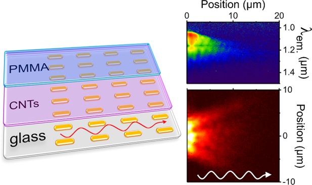
Strong coupling between plasmons and excitons leads to the formation of plexcitons: quasiparticles that combine nanoscale energy confinement and pronounced optical nonlinearities. In addition to these localized modes, the enhanced control over the dispersion relation of propagating plexcitons may enable coherent and collective coupling of distant emitters. Here, we experimentally demonstrate strong coupling between carbon nanotube excitons and spatially extended plasmonic modes formed via diffractive coupling of periodically arranged gold nanoparticles (nanodisks, nanorods). Depending on the light-matter composition, the rather long-lived plexcitons (>100 fs) undergo highly directional propagation over 20 μm. Near-field energy distributions calculated with the finite-difference time-domain method fully corroborate our experimental results. The previously demonstrated compatibility of this plexcitonic system with electrical excitation opens the path to the realization of a variety of ultrafast active plasmonic devices, cavity-assisted energy transport and low-power optoelectronic components.
Keywords: Plexcitons, strong coupling, carbon nanotubes, plasmonic crystals, light emission, radiative pumping
The nanoscale localization of
electromagnetic energy in the vicinity of metallic nanostructures
opens a range of possibilities for fundamental studies and manipulation
of light-matter interaction.1−3 The large local field intensities
and subdiffraction confinement associated with the surface plasmon
resonances in such nanocavities is particularly promising for strong
coupling with light emitters. In the simplest form, the coupling strength
(g) is tuned via the cavity mode volume (V), number of emitters (N) that collectively
couple to the nanocavity (if many) and their oscillator strength (f),  . At the extreme limit, i.e., when the coupling
between plasmons and emitters exceeds the total damping rate of the
system, the strong coupling regime emerges with the formation of new
hybrid quasi-particles, plasmon-exciton polaritons (plexcitons for short). The associated excitonic nonlinearities and ultrafast
energy exchange enable their active high-speed control, which is important
for fundamental science and practical all-optical information processing
technologies.1,4
Plexcitons can be achieved with various materials, including organic semiconductors,5−12 quantum dots,13,14 quantum wells,15 carbon nanotubes,16 and transition metal dichalcogenides.15,17,18 For plasmonic nanocavities, it is common to implement structures supporting localized surface plasmons (LSPs) such as nanoshells,9,14 nanoprisms,12,19 disks,7 spheres,8 nanorods8,10,18 and dimers.11,20 Owing to the ultrasmall mode confinement, even a single plexciton regime under room temperature conditions could be reported.5,13,20 In addition to localized modes, more spatially extended and propagating plexcitons6,15,21 are considered promising for the coupling of distant emitters22 and large spatial coherence of light emission.21 One attractive design involves the collective resonances in one- and two-dimensional periodic metallic structures.4,16,23,24 Due to their hybrid plasmonic–photonic character they possess reasonably high-quality factors (Q ∼ 100) and thus longer lifetimes compared to LSPs. Furthermore, the overall plasmon/exciton/polariton composition of the formed plexcitons enables a straightforward tunability of nanoscale confinement, optical nonlinearities and quality factors.
Another degree of optimization is possible via tailoring plexciton band structure that defines the relaxation dynamics (via the excitonic part) and anisotropy of the plexciton effective mass (photonic component). These characteristics are crucial for the improved design of macroscopic coherent states, nanoscale lasing,23 long-range and directional energy transport.25 Despite the fundamental and technological implications, their anisotropic properties are usually addressed only along specific directions or at certain angular dispersion points.26−28 Moreover, the corresponding experimental studies, e.g., via the spatial dynamics of propagating plexcitons, are complicated by their relatively short lifetime (approximately a few tens or hundreds of femtoseconds).
With the aim to investigate the spatial and energetic properties of propagating plexcitons, we demonstrate the collective coupling of single-walled carbon nanotube excitons with hybrid plasmonic-photonic modes. The latter are supported in plasmonic crystals formed by the diffractive coupling of periodically arranged gold nanodisks or nanorods. Semiconducting single-walled carbon nanotubes are used owing to their advantageous properties to strong coupling regime,16,29 and the ability of easy electrical exciton generation and electric field gating.30,31 By implementing their in-plane orientation and an indirect radiative pumping scheme, we eliminate spatial variation imposed by the excitation source and directly visualize the propagation of plexcitons via their radiative decay. Through extensive analysis of the theoretical and experimental two-dimensional band-structure, we are able to reconstruct a complex set of anisotropic features such as plexciton group velocity (≤200 μm/ps), effective mass (≥10–7 of electron mass) and spatial coherence length (≤20 μm). The numerically simulated near-field energy distributions (by finite-difference time-domain method, FDTD) fully support our experimental findings.
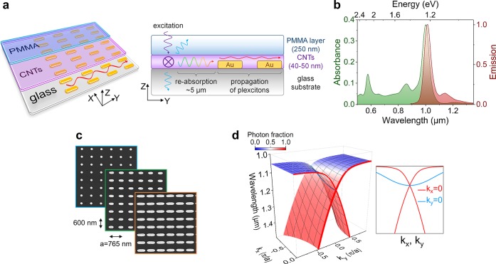
To investigate the propagation features of plexcitons in 2D plasmonic crystals, we designed and fabricated a sample schematically shown in Figure 1a. It consists of a glass substrate, periodically arranged plasmonic particles (nanodisks or nanorods), supporting LSPs (array area 100 × 100 μm2), and a thin but dense layer (∼40–50 nm) of aerosol-jet printed32 polymer-wrapped33 (6,5) single-walled carbon nanotubes (CNTs) covered by a 250 nm PMMA film that homogenizes the dielectric environment (see the Supporting Information for details of sample fabrication). In contrast to our previous studies on plexcitons with a relatively thick 300 nm CNT layer,16 we employed a thinner but denser and homogeneous printed CNT layer that ensured a similar degree of collective coupling between the plasmonic crystal and CNTs. The plexciton generation scheme involves laser excitation of the randomly, in-plane oriented carbon nanotubes at a position 5 μm from the edge of the plasmonic crystal. The typical absorption and emission spectra of noncoupled (6,5) single-walled carbon nanotubes are shown in Figure 1b (see the photoluminescence-excitation map in the Supporting Information, Figure S1). Due to their small Stokes shift, the photons emitted from the photoexcited CNTs will be absorbed upon in-plane propagation (over 5 μm) and only those with wavelengths above ∼1050–1100 nm can reach the plasmonic crystal and excite plexcitons. In this configuration, the radiative decay of propagating plexcitons is less prone to the distortion imposed by the laser excitation profile.
Figure 1.
(a) Schematic sample layout consisting of a glass substrate, plasmonic crystal, a layer of randomly in-plane oriented (6,5) CNTs and a PMMA film. The indirect excitation of plexcitons is performed via light emission from the carbon nanotubes pumped at a position 5 μm from the edge of the plasmonic crystal. (b) Absorption and photoluminescence spectra of a 40–50 nm thick film of (6,5) CNTs. (c) Scanning electron micrographs of gold nanodisks (diameter 165 nm) and two types of nanorods (380 × 180 nm and 620 × 200 nm). All plasmonic crystals have 765 nm pitch along the main propagation direction (Y-axis) and 600 nm in the orthogonal direction (X-axis). (d) 3D representation of the plexcitonic λ(kx, ky) dispersion. Color scale represents variation of photon and matter (excitonic + plasmonic) fractions. The inset compares the dispersion along X (ky = 0) and Y directions (kx = 0).
Due to the hybrid plasmonic–photonic nature of the modes occurring in plasmonic crystals, they are intrinsically mediated by the LSPs of the constituting particles. To test the potential impact of the particles’ aspect ratio on the plexciton propagation characteristics, different structures were fabricated, such as nanodisks (D = ∼165 nm), and two types of nanorods with a length × width of 380 × 180 nm (“small”) and 620 × 200 nm (“large”), as shown in Figure 1c. The height was fixed to 25 nm and periodicity along X and Y directions was set to 600 and 765 nm, respectively. The size of the particles (which tunes LSPs spectral position) and their periodicity (which defines the photonic modes, i.e., diffraction orders)34 were tailored to support high-quality modes extending along the Y-axis and spectrally close to the excitonic transitions of the (6,5) CNTs. At the same time, the generation of plexcitons propagating along the X-axis was less efficient, due to the large detuning between the longitudinal LSPs and the associated diffraction orders (see Supporting Information, Figure S2).
Upon coupling of the carbon nanotubes to the plasmonic crystals, the formed plexciton states are mostly defined by the dispersion relation of the diffraction orders, as shown in Figure 1d. To reconstruct the band structure, the coupling strengths between excitonic, plasmonic and (0,+1)/(0,–1) counterpropagating photonic modes were extracted from the coupled-oscillator model fit of the experimental data as discussed below. The color scale highlights the gradual transition from mostly matter (plasmonic + excitonic) to photonic character for longer wavelengths. The associated wavelength dependence of the steepness (i.e., dλ/dk ∝ group velocity) also enables the excitation of either localized or more propagating and delocalized plexcitons.
Initial FDTD simulations allowed us to estimate the degree of propagation for a sample design as shown in Figure 1a. The CNT layer was represented by the Lorentz oscillator dielectric permittivity with parameters adjusted to fit the experimental absorption spectrum in Figure 1b. The photoexcited CNTs were simulated by a broadband X-polarized emitting dipole that was placed 5 μm from the edge of the plasmonic crystal (see Supporting Information for simulation details). This corresponds to Z = 0 and Y = −5 μm for the YZ-cross section field intensity distribution in Figure 2. It is worth noting that the plexciton propagation length varies significantly with the wavelength (values of the reference configuration, i.e., without the plasmonic crystal, were subtracted for clarity). As expected for wavelengths closer to the absorption band and where plexcitons are mostly matter-like (λ = 1050 nm), almost no energy propagates in the plane of the nanoparticle array (∼Z = 0 nm). This is in contrast to the wavelengths with negligible reabsorption (λ = 1150, 1300 nm) and where clear propagation over 20 μm can be observed.
Figure 2.
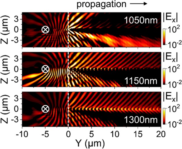
Calculated electric field distribution (YZ planes, for X = 0 μm) from an X-polarized dipole located 5 μm (at Y = −5 μm, Z = 0 μm) from the edge of the plasmonic crystal for three representative wavelengths λ = 1050, 1150, and 1300 nm. The field distribution in the absence of the plasmonic crystal was subtracted for clarity.
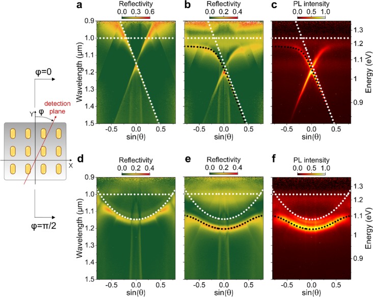
Next, we performed reflectivity and photoluminescence angular dispersion measurements in the center of the plasmonic crystal to experimentally confirm the formation of plexcitons, as shown in Figure 3 for small nanorods (380 × 180 nm) (see Supporting Information for experimental details and Figures S3 and S4 for data from nanodisks and large nanorods). The schematic also indicates the planes for which light was collected, that is, along or orthogonal to the main propagation axis. First, for the initial hybrid plasmonic-photonic modes of the plasmonic crystal (i.e., without carbon nanotubes), one can clearly identify their high-quality factors with high angular dispersion along Y-axis (Figure 3a). Upon adding carbon nanotubes with excitonic transitions at λ = 1000 nm, the strong hybridization between (0,+1)/(0,–1) diffraction order, localized surface plasmons and excitons is evident by the anticrossing in both reflectivity and photoluminescence data (Figure 3b,c). Although less pronounced due to the larger detuning, similar tendencies can be observed along the X-axis in Figure 3d–f. To quantify the strong light-matter coupling, the photoluminescence data was fitted to the coupled-oscillator model where the corresponding coupling strengths between the initial states (white dotted lines in Figure 3) were the fitting parameters. In general, a reasonable quality of the fits is observed for the plexciton modes (black dotted lines). The exciton-LSP/diffraction order coupling strengths were found to be in the range of 98–125/38–83 meV, depending on the nanoparticle shape (i.e., nanodisks or nanorods), while the LSP-diffraction order coupling was almost negligible (see Supporting Information for details). The latter is caused by the larger detuning between LSPs (ELSP ∼ 1.4 eV) and diffraction orders compared to the excitons (Eex. = 1.24 eV).
Figure 3.
Angular dispersion of a sample with small nanorods (380 × 180 nm) without (a, reflectivity) and with (b and c, reflectivity and photoluminescence, respectively) carbon nanotubes measured along the Y-axis. (d–f) Corresponding data for the detection along X-axis. White dotted lines indicate the bare excitonic (dispersionless) and diffraction order, while the black dotted lines correspond to the fitted plexciton modes.
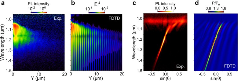
To experimentally visualize and characterize the propagation of plexcitons, we performed real-space imaging of their radiative decay during propagation into the plasmonic crystal as shown in Figure 4a. The reference light emission without the plasmonic crystal was subtracted for clarity. The photoluminescence intensity directly correlates with the spatial distribution of the plexcitons and their population. The clear edge where plexcitons are excited is visible at Y = 0 μm for the excitation spot at Y= −5 μm and X = 0 μm. It is indicative that the plexcitons propagate mostly along a specific range of directions, i.e., within ±40°. A similar trend is observed for the nanodisks, while a slightly faster decay is seen for large nanorod arrays (see Supporting Information, Figure S5). Due to the wavelength summation over the emission spectrum in the detected signal, additional simulations shed more light on the energy dependence of plexciton propagation. The corresponding in-plane profiles of local field intensities at λ = 1050, 1150, and 1300 nm show interesting variations of both propagation length and directionality (Figure 4b–d). For the wavelength range with higher CNT absorption, plexcitons quickly decay within the first couple of micrometers that is in accordance with the field distributions in Figure 2. On the other hand, for the most photonic-like excitations (λ = 1300 nm), the plexcitons demonstrate long-range propagation with directionality patterns similar to the experimental data. It is worth noting that selecting the intermediate wavelength range (λ = 1150 nm), an even higher directionality can be achieved, yet with slightly shorter propagation distance.
Figure 4.
(a) Spectrum-integrated radiative decay and upward propagation of the plexcitons into the plasmonic crystal. Light emission from a region with only carbon nanotubes was subtracted for clarity. (b–d) Calculated sum of electric near-field distributions (XY plane, for Z = 0 μm) from X- and Y-polarized dipoles located 5 μm (at Y = −5 μm; X, Z = 0 μm) from the edge of plasmonic crystal for three representative wavelengths λ = 1050, 1150, and 1300 nm.
The complementary hyperspectral images along the propagation direction (i.e., Y-axis for X = 0 μm, white dashed line in Figure 4a) help to gain further insights into the wavelength dependence of the propagation, as shown in Figure 5a. For the λ = 1050–1200 nm spectral range, one can clearly see the increased propagation for longer wavelengths. It is important to note that although beyond this range (λ > 1200 nm) plexcitons seem to decay faster, the trend is only apparent due to the lower plexciton population that follows the emission spectrum of CNTs. As for the angular distribution of the plexciton radiative decay, it is mostly dominated by the state associated with a single (0,+1) diffraction order (see eq 3 in the Supporting Information), as shown in Figure 5c. Note that although the energy flow, and thus plexcitons group velocity is directed into the plasmonic crystal, the phase velocity (characterized by the emission angle) can be along (λ < 1170 nm) or in the opposite (λ > 1170 nm) direction. Comparable hyperspectral and angular emission features are observed for nanodisk and large nanorod arrays (see Supporting Information, Figures S6 and S7). Additional simulations of local field distribution (Figure 5b) and far-field emission patterns (Figure 5d) show an excellent agreement with the experimental data.
Figure 5.
Hyperspectral image (a) and angular distribution (c) of the radiative decay of plexcitons along propagation direction (Y-axis, for X = 0 μm). Corresponding calculated hyperspectral near-field intensity distribution (b) and far-field angular distribution (d). The excitation spot is located 5 μm from the edge of the plasmonic crystal both in the experimental and simulated data.
In order to quantify
the plexciton dynamics and spatial coherence
of light emission, first, we estimated the group velocity35 of the plexcitons  from their dispersion
along the Y- and X-axes as a function
of k-vector (Figure 6, parts a and c). In addition, to improve quality of
the calculations
and as a guide to the trends, we included the corresponding velocities
and photon fractions of the plexcitons estimated from the coupled-oscillator
model that was fitted to the experimental dispersions. One can clearly
see that the absolute values differ significantly for the two orthogonal
directions, with velocities reaching the speed of light in a medium
(c/n, with n =
1.5) for the dominant propagation direction (Y-axis).
This increase in the group velocity correlates with the higher photon
fraction of plexcitons for negative k-vector values
(or angles in Figure 5c). Surprisingly, all three nanoparticle geometries (i.e., nanodisks
and nanorods) show similar trends. Slight deviations are evident at
shorter/positive k-values for the large nanorod plexcitons
that are more matter-like due to their higher admixture of localized
surface plasmons (Figure 6a). Further, the propagation distances are calculated from
the group velocities and dispersion linewidth ΔE of the plexciton mode (i.e., corresponding to
lifetime, τ = 2ℏ/ΔE),36 as shown in Figure 6, parts b and d. Here again the larger propagation
lengths correspond to the plexcitons with higher photon fraction due
to the simultaneous contribution of higher group velocity and plexciton
lifetime. Owing to the coherent coupling of carbon nanotubes across
the plasmonic crystal via extended plasmon-photonic modes, the spatial
coherence of light emission can be deduced from the dispersion linewidth Δk as L(kx, ky) = 2/Δkx,y.6 A very good agreement
between
coherence and propagation lengths for the Y-axis
is observed. The smaller values for the array consisting of large
nanorods relate to their shorter lifetime (see Supporting Information, Figure S7a). As for the orthogonal
direction, the discrepancies appear for all nanoparticle arrays at
small k-vectors, most likely originating from the
plexciton energy relaxation and/or the spatial extension of the excitation
region seen in Figure 4a.
Figure 6.
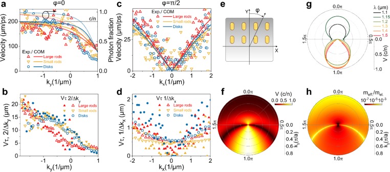
Propagation velocities for plexcitons along Y-axis (a) and X-axis (c) for three different plasmonic crystals calculated from the angular dispersions compared to the values extracted from the coupled-oscillator model. The photon fractions correlate with the increase of velocity reaching the speed of light in a medium c/n with n = 1.5. Corresponding propagation lengths for plexcitons along Y-axis (b) and X-axis (d) calculated from their velocities and lifetimes compared to the spatial coherence lengths extracted from the reciprocal-space linewidth. Calculated polar plots of normalized group velocities (f) and effective masses (h) of plexcitons along phase velocity directions indicated in part e. (g) Group velocity polar plots for plexcitons of different wavelengths.
Given the very good agreement between group velocities
calculated
from the experimental data and the coupled-oscillator model, we can
easily generalize our approach for all in-plane directions (see schematics
in Figure 6e). To facilitate
the calculations and for clarity, the polar plot was chosen with k∥ (in-plane k-vector
component) and φ (polar angle) coordinates that define the corresponding
Cartesian projections: kx = k∥ sin(φ) and ky = k∥ cos(φ) . First, the group velocities in Figure 6f show a complex
direction and k-vector dependence reaching c/n values mainly along the Y-axis as discussed before. This ballistic motion of plexcitons with
several micrometers propagation distance are of high practical importance
for devices where the exciton diffusion is a main transport mechanism
(i.e., with a typical diffusion length about tens or hundreds of nanometers).25 Furthermore, our findings can be easily generalized
beyond the carbon nanotubes to other materials that support strong
coupling regime. Second, the propagation speed is connected to the
effective inertial mass35 of the plexcitons  and shown in Figure 6h (normalized to
the electron mass mel.). The very low mass (7
orders of magnitude lower than mel.) highlights the great potential of plasmonic crystals to reach
low-threshold plexcitonic23 or plasmon-polariton37 lasing. The critical density of bosons (plexcitons
or polaritons) necessary for the condensation in such an extended
2D systems scales approximately as nc ∝ meff. It is important to note that a stopgap opening in the dispersion
is not pronounced in our samples (see Figures 3, S3, S4, and S7). However, for arrays with larger particle polarizability,38 it is expected that the stopgap will appear
leading to a higher effective mass at the band edge.
Apart from these anisotropic properties of effective mass and velocity, it is also advantageous to calculate direction and propagation speed for plexcitons at specific wavelengths. Toward this end, the velocity was deduced for several representative isoenergetic contours (i.e., cross sections of λ (k∥,φ) dispersion), as summarized in Figure 6g. These results support the propagation directionality patterns within ±40–45° shown in Figure 4. It also defines the angular range for which plexcitons can be excited, and thus explains the spatial expansion (along the X-axis) of the light emission at the edge of the plasmonic crystal excited by the point source at 5 μm (Figure 4a). It is important to remember that for the wavelengths above ∼1170 nm, the phase velocity direction is opposite to the group velocity plotted in Figure 6g.
In summary, we have observed the anisotropic propagation of plexcitons in diffractive plasmonic crystals strongly coupled to semiconducting carbon nanotubes. For the first time, a comprehensive set of experimental characterization and theoretical analysis allowed us to reconstruct the full k-vector dependence of the plexciton effective mass and propagation velocities. Apart from the variation of lifetime, the nanoparticle shape and size played only a minor role in the plexciton state dispersion. The high compatibility of our system with electrical excitation,31,39 and the robustness of strong light-matter coupling in carbon nanotubes at high current densities30 opens pathways for the realization of ultrafast active plasmonic devices and low-power/energy optoelectronic components.
Acknowledgments
This research was financially supported by the European Research Council under the European Union’s Seventh Framework Programme (FP/2007-2013)/ERC Grant Agreement 306298 (EN-LUMINATE).
Supporting Information Available
The Supporting Information is available free of charge on the ACS Publications website at DOI: 10.1021/acs.nanolett.8b01733.
Sample fabrication, characterization, and theoretical analysis, photoluminescence excitation map of the CNT layer, localized surface plasmons of nanodisks and nanorods, angular dispersion (reflectivity and photoluminescence) of samples with large nanorods and nanodisks, and spectrum-integrated and hyperspectral and angular distribution of radiative decay and propagation of the plexcitons (PDF)
Author Present Address
§ Department of Physics, Technical University of Denmark, 2800 Kongens Lyngby, Denmark
The authors declare no competing financial interest.
Supplementary Material
References
- Tame M. S.; McEnery K. R.; Özdemir Ş. K.; Lee J.; Maier S. A.; Kim M. S. Nat. Phys. 2013, 9, 329–340. 10.1038/nphys2615. [DOI] [Google Scholar]
- Brongersma M. L.; Halas N. J.; Nordlander P. Nat. Nanotechnol. 2015, 10, 25–34. 10.1038/nnano.2014.311. [DOI] [PubMed] [Google Scholar]
- Schuller J. A.; Barnard E. S.; Cai W.; Jun Y. C.; White J. S.; Brongersma M. L. Nat. Mater. 2010, 9, 193–204. 10.1038/nmat2630. [DOI] [PubMed] [Google Scholar]
- Vasa P.; Wang W.; Pomraenke R.; Lammers M.; Maiuri M.; Manzoni C.; Cerullo G.; Lienau C. Nat. Photonics 2013, 7, 128–132. 10.1038/nphoton.2012.340. [DOI] [Google Scholar]
- Chikkaraddy R.; de Nijs B.; Benz F.; Barrow S. J.; Scherman O. A.; Rosta E.; Demetriadou A.; Fox P.; Hess O.; Baumberg J. J. Nature 2016, 535, 127–130. 10.1038/nature17974. [DOI] [PMC free article] [PubMed] [Google Scholar]
- Chevrier K.; Benoit J.-M.; Symonds C.; Paparone J.; Laverdant J.; Bellessa J. ACS Photonics 2018, 5, 80–84. 10.1021/acsphotonics.7b00556. [DOI] [Google Scholar]
- Todisco F.; De Giorgi M.; Esposito M.; De Marco L.; Zizzari A.; Bianco M.; Dominici L.; Ballarini D.; Arima V.; Gigli G.; Sanvitto D. ACS Photonics 2018, 5, 143–150. 10.1021/acsphotonics.7b00554. [DOI] [Google Scholar]
- Thomas R.; Thomas A.; Pullanchery S.; Joseph L.; Somasundaran S. M.; Swathi R. S.; Gray S. K.; Thomas K. G. ACS Nano 2018, 12, 402–415. 10.1021/acsnano.7b06589. [DOI] [PubMed] [Google Scholar]
- Fofang N. T.; Grady N. K.; Fan Z.; Govorov A. O.; Halas N. J. Nano Lett. 2011, 11, 1556–1560. 10.1021/nl104352j. [DOI] [PubMed] [Google Scholar]
- Nan F.; Zhang Y.-F.; Li X.; Zhang X.-T.; Li H.; Zhang X.; Jiang R.; Wang J.; Zhang W.; Zhou L.; Wang J.-H.; Wang Q.-Q.; Zhang Z. Nano Lett. 2015, 15, 2705–2710. 10.1021/acs.nanolett.5b00413. [DOI] [PubMed] [Google Scholar]
- Schlather A. E.; Large N.; Urban A. S.; Nordlander P.; Halas N. J. Nano Lett. 2013, 13, 3281–3286. 10.1021/nl4014887. [DOI] [PubMed] [Google Scholar]
- Balci S.; Kucukoz B.; Balci O.; Karatay A.; Kocabas C.; Yaglioglu G. ACS Photonics 2016, 3, 2010–2016. 10.1021/acsphotonics.6b00498. [DOI] [Google Scholar]
- Groß H.; Hamm J. M.; Tufarelli T.; Hess O.; Hecht B. Sci. Adv. 2018, 4, eaar4906. 10.1126/sciadv.aar4906. [DOI] [PMC free article] [PubMed] [Google Scholar]
- Zhou N.; Yuan M.; Gao Y.; Li D.; Yang D. ACS Nano 2016, 10, 4154–4163. 10.1021/acsnano.5b07400. [DOI] [PubMed] [Google Scholar]
- Wurdack M.; Lundt N.; Klaas M.; Baumann V.; Kavokin A. V.; Höfling S.; Schneider C. Nat. Commun. 2017, 8, 259. 10.1038/s41467-017-00155-w. [DOI] [PMC free article] [PubMed] [Google Scholar]
- Zakharko Y.; Graf A.; Zaumseil J. Nano Lett. 2016, 16, 6504–6510. 10.1021/acs.nanolett.6b03086. [DOI] [PMC free article] [PubMed] [Google Scholar]
- Lee B.; Liu W.; Naylor C. H.; Park J.; Malek S. C.; Berger J. S.; Johnson A. T. C.; Agarwal R. Nano Lett. 2017, 17, 4541–4547. 10.1021/acs.nanolett.7b02245. [DOI] [PubMed] [Google Scholar]
- Zheng D.; Zhang S.; Deng Q.; Kang M.; Nordlander P.; Xu H. Nano Lett. 2017, 17, 3809–3814. 10.1021/acs.nanolett.7b01176. [DOI] [PubMed] [Google Scholar]
- Wersäll M.; Cuadra J.; Antosiewicz T. J.; Balci S.; Shegai T. Nano Lett. 2017, 17, 551–558. 10.1021/acs.nanolett.6b04659. [DOI] [PubMed] [Google Scholar]
- Santhosh K.; Bitton O.; Chuntonov L.; Haran G. Nat. Commun. 2016, 7, 11823. 10.1038/ncomms11823. [DOI] [PMC free article] [PubMed] [Google Scholar]
- Aberra Guebrou S.; Symonds C.; Homeyer E.; Plenet J. C.; Gartstein Y. N.; Agranovich V. M.; Bellessa J. Phys. Rev. Lett. 2012, 108, 66401. 10.1103/PhysRevLett.108.066401. [DOI] [PubMed] [Google Scholar]
- Zheng H.; Baranger H. U. Phys. Rev. Lett. 2013, 110, 113601. 10.1103/PhysRevLett.110.113601. [DOI] [PubMed] [Google Scholar]
- Ramezani M.; Halpin A.; Fernández-Domínguez A. I.; Feist J.; Rodriguez S. R.-K.; Garcia-Vidal F. J.; Gómez Rivas J. Optica 2017, 4, 31. 10.1364/OPTICA.4.000031. [DOI] [Google Scholar]
- Shi L.; Hakala T. K.; Rekola H. T.; Martikainen J.-P.; Moerland R. J.; Törmä P. Phys. Rev. Lett. 2014, 112, 153002. 10.1103/PhysRevLett.112.153002. [DOI] [PubMed] [Google Scholar]
- Orgiu E.; George J.; Hutchison J. A.; Devaux E.; Dayen J. F.; Doudin B.; Stellacci F.; Genet C.; Schachenmayer J.; Genes C.; Pupillo G.; Samorì P.; Ebbesen T. W. Nat. Mater. 2015, 14, 1123–1129. 10.1038/nmat4392. [DOI] [PubMed] [Google Scholar]
- Ramezani M.; Halpin A.; Feist J.; Van Hoof N.; Fernández-Domínguez A. I.; Garcia-Vidal F. J.; Gómez Rivas J. ACS Photonics 2018, 5, 233–239. 10.1021/acsphotonics.7b00661. [DOI] [Google Scholar]
- Rodriguez S. R. K.; Feist J.; Verschuuren M. A.; Garcia Vidal F. J.; Gómez Rivas J. Phys. Rev. Lett. 2013, 111, 166802. 10.1103/PhysRevLett.111.166802. [DOI] [PubMed] [Google Scholar]
- Vecchi G.; Giannini V.; Gómez Rivas J. Phys. Rev. B: Condens. Matter Mater. Phys. 2009, 80, 201401. 10.1103/PhysRevB.80.201401. [DOI] [Google Scholar]
- Graf A.; Tropf L.; Zakharko Y.; Zaumseil J.; Gather M. C. Nat. Commun. 2016, 7, 13078. 10.1038/ncomms13078. [DOI] [PMC free article] [PubMed] [Google Scholar]
- Graf A.; Held M.; Zakharko Y.; Tropf L.; Gather M. C.; Zaumseil J. Nat. Mater. 2017, 16, 911–917. 10.1038/nmat4940. [DOI] [PubMed] [Google Scholar]
- Zakharko Y.; Held M.; Graf A.; Rödlmeier T.; Eckstein R.; Hernandez-Sosa G.; Hähnlein B.; Pezoldt J.; Zaumseil J. Opt. Express 2017, 25, 18092. 10.1364/OE.25.018092. [DOI] [PubMed] [Google Scholar]
- Rother M.; Brohmann M.; Yang S.; Grimm S. B.; Schießl S. P.; Graf A.; Zaumseil J. Adv. Electron. Mater. 2017, 3, 1700080. 10.1002/aelm.201700080. [DOI] [Google Scholar]
- Graf A.; Zakharko Y.; Schießl S. P.; Backes C.; Pfohl M.; Flavel B. S.; Zaumseil J. Carbon 2016, 105, 593–599. 10.1016/j.carbon.2016.05.002. [DOI] [Google Scholar]
- Kravets V. G.; Schedin F.; Grigorenko A. N. Phys. Rev. Lett. 2008, 101, 87403. 10.1103/PhysRevLett.101.087403. [DOI] [PubMed] [Google Scholar]
- Colas D.; Laussy F. P. Phys. Rev. Lett. 2016, 116, 26401. 10.1103/PhysRevLett.116.026401. [DOI] [PubMed] [Google Scholar]
- Sönnichsen C.; Franzl T.; Wilk T.; von Plessen G.; Feldmann J.; Wilson O.; Mulvaney P. Phys. Rev. Lett. 2002, 88, 77402. 10.1103/PhysRevLett.88.077402. [DOI] [PubMed] [Google Scholar]
- Hakala T. K.; Moilanen A. J.; Väkeväinen A. I.; Guo R.; Martikainen J.-P.; Daskalakis K. S.; Rekola H. T.; Julku A.; Törmä P. Nat. Phys. 2018, 14, 739. 10.1038/s41567-018-0109-9. [DOI] [Google Scholar]
- Schokker A. H.; van Riggelen F.; Hadad Y.; Alù A.; Koenderink A. F. Phys. Rev. B: Condens. Matter Mater. Phys. 2017, 95, 85409. 10.1103/PhysRevB.95.085409. [DOI] [Google Scholar]
- Zakharko Y.; Held M.; Graf A.; Rödlmeier T.; Eckstein R.; Hernandez-Sosa G.; Hähnlein B.; Pezoldt J.; Zaumseil J. ACS Photonics 2016, 3, 2225–2230. 10.1021/acsphotonics.6b00491. [DOI] [PMC free article] [PubMed] [Google Scholar]
Associated Data
This section collects any data citations, data availability statements, or supplementary materials included in this article.


