

Abstract
Electrode fabrication and membrane electrode assembly (MEA) processes are critical steps in polymer electrolyte membrane fuel cell (PEMFC) technology. The properties of decal substrate material are important in decal coating technique for efficient transfer of catalyst layer. In the present study, MEAs are fabricated in decal method using 6 different decal substrates among which polypropylene (PP) is found ideal. Morphological, thermal, spectroscopic and sessile drop measurements are conducted for 6 decal substrates to evaluate the thermal and physicochemical properties. Studies indicate PP is thermally stable at hot-press conditions, having optimal hydrophobicity that hinders the coagulation of catalyst ink slurry cast. The pristine PP film has been identified to showcase 100% transfer yield onto the Nafion membrane without contamination and delamination of catalyst layer from membrane. The PP based MEAs are evaluated underconstant current mode in a hydrogen-oxygen fuel cell test fixture. The performance is found to be of 0.6 V at a constant current density of 1.2 A.cm−2. Besides, the cost of PP-film is only 7.5% of Kapton-film, and hence the current research work enables the high throughput electrode fabrication process for PEMFC commercialization.
Introduction
Gross domestic product (GDP) of developing countries benefit with close causation to the energy production and its consumption1,2. Increased energy consumption and forefront global issues have led to renewed focus on energy generation and storage. Henceforth, energy security is a promising area of research to public and private governing bodies. The upcoming decades are full of quest for renewable energy conversion and storage devices. Hence hybrid systems that comprises fuel cells, batteries, super capacitors and hybrid of these act as pivot for this energy sustainability3. In particular, fuel cell plays a critical role for rural as well as sub-urban electrification, and as off-grid back up power source in telecom industry for many countries4–6. In fuel cell system, balance of plant (BOP) and stack development encompass 71% of the fuel cell system cost7. Therefore, it is of fundamental challenge for scientists to decrease the costs of stack components without compromising the electrochemical performance. Essentially, fuel cell stack is engineered with critical components such as membrane electrode assemblies (MEAs), bipolar plates, current collector plates, endplates etc. MEA is considered as the heart of the fuel cell and is the epicentre for electrochemical reactions that generate electricity8,9. Therefore, MEA fabrication with precision engineering is of fundamental interest and many routes have been put forth considering cost, performance and other entities10,11.
Among the various techniques of MEA development, studies have shown that decal technique has improved efficiency over spray and other conventional coating techniques12,13. In decal method, the substrates are coated with the catalyst inks, dried and later transferred to a membrane of interest to fabricate the MEA. Conventionally, polytetrafluoroethylene (PTFE) and polyimide (Kapton) films are well known decal substrates for fabricating MEA by decal method. The prominent features of the decal substrates are: (1) The substrate must be chemically inert to the coated catalyst layer, (2) Substrate should not also poison the catalyst during the hydraulic hot-press conditions of the MEA, (3) The hydrophilic nature of the substrate helps to avoid the formation of micro islands of the catalyst ink14. (4) The substrate thickness must be less than 50 micron to gain an advantage of easy peel off, after the hot-press of MEA. (5) The substrate must be cost effective for commercial scale up.
It is necessary to understand the structural properties of the decal substrate/films to elucidate the chemical interaction between ionomer/Nafion and the decal substrate. When PTFE is used as the decal substrate, due to increased chemical interaction between PTFE and Nafion only partial catalyst transfer has been observed during the hydraulic hot-press subjection (Fig. 1). Irmawati et al.15 has concluded that PTFE cloth and film furnish only 90% catalyst transfer. Similar works of Shahgaldi et al.16 has observed only 85% catalyst transfer yield using PTFE as substrate. Furthermore, it has been studied that fluorinated ethylene propylene substrate has the best catalyst transfer efficiency. To achieve this an additional coat of Nafion over the catalyst coated decal substrate with a loading of at least 0.2 mg. cm−2 is necessary prior to hot-pressing with the membrane (Table 1)16. However, Sasikumar et al. has disclosed that more than 30 wt.% Nafion ionomer loadings will block the meso-nano pores of the catalyst layer which hinders the performance of fuel cell17–19. Other decal substrates such as aluminium foil, stainless steel, perfluoroalkoxy polymer, polytetrafluoroethylene, Kapton HN (Polyimide), and Kapton FN (80% polyimide and 20% fluorinated ethylene propylene (FEP)) etc. have also been considered with partial catalyst transfer and low transfer efficiency (Table 1). Therefore, it is vital to understand the chemistry of the decal substrates along with economics to achieve complete catalyst transfer for an industrial MEA development. Many decal substrates are reported with complete catalyst transferability such as PP, Kapton HN, polyethylene(PE) films, however they are only qualitative claims20. Furthermore, to the best of our knowledge, no literature is available related to ideal decal substrates for the complete transfer of catalyst layer to the Nafion.
Figure 1.
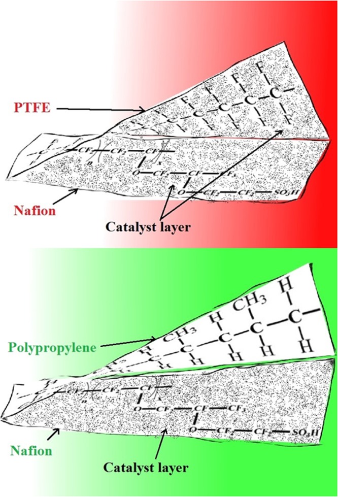
Schematic representation of physicochemical interaction between the PP and PTFE decal films with Nafion based catalyst layer after hot-pressing of the MEA.
Table 1.
Type of decal substrate and catalyst transfer ability.
In the present work, an extensive study has been carried-out with a quest to find outcost effective, 100% catalyst transferable decal substrate. Hence PP, Low-density polyethylene (LDPE), Silicone coated polyethylene terephthalate (Si-PET), Polytetrafluoroethylene/Teflon (PTFE), Reinforced-polytetrafluoroethylene (RPTFE), Kapton films has been selected. The substrates are evaluated for their properties that are relevant towards MEA fabrication. During MEA fabrication, a blend of physicochemical properties such as thermal stability, chemical inertness of the substrate plays a key role. We identify PP as complete catalyst transfer decal substrate. The other benefits with PP use are low cost, non-poisoning of the catalyst, high electrochemical performance upon MEA fabrication. The cost of PP is just only $ 18.m−2 and for Kapton it is $ 240.m−2, this research therefore drastically brings down the cost of MEA fabrication. Since MEA is the heart of the fuel cell, this is a giant leap for PEMFC commercialization. The detailed scientific aspects of the decal substrates and their catalyst interactions have been discussed in the subsequent sections.
Results and Discussion
The complete catalyst transfer over the Nafion after the hot-press is a crucial step. The MEA fabrication efficiency is evaluated in terms of percentage transfer of the catalyst ink and catalyst rejuvenation post fabrication. The percentage transfer of the catalyst is evaluated for different substrates using hot-press and the tabulated in Table 2.
Table 2.
Different parameters that affect the decal based MEA fabrication using different substrates.
| Substrate Name | Thickness of substrate (micron meter) | Catalyst layer transfer percentage | Poisoning | Scalability |
|---|---|---|---|---|
| PP | 30 | 100 | × | ✓ |
| LDPE | 30 | 100 | ✓ | × |
| Si-PET | 50 | 95 | × | × |
| Kapton HN | 15 | 92 | × | ✓ |
| PTFE | 90 | 64 | × | × |
| RPTFE | 220 | 72 | × | × |
PP has 100% transferability than any another conventional substrates such as Si-PET, Kapton, PTFE and RPTFE. It is evident from the tabulated data, because of thermal and chemical stabilities during hot-press step, the thin PP film are effectively used to transfer the catalyst. During hot press, the use of Teflon as substrate has provided low percentage of catalyst transfer towards the Nafion membrane. Further, in terms of the case of manufacturing & scalability, PP and Si-PET substrates are cost effective films at a commercial scale. Conversely, other decal substrate due to hydrophobicity forms isolated/islands of catalyst ionomer segregation causing hot spots over the MEA, this directly diminish the quality of the MEAs14. Hence, surface chemistry, structural and thermal stabilities of selected substrates are crucial and discussed in the latter sections.
A skin tattoo inspired decal substrates peel off from the Nafion membrane after hot-press. The Fig. 1 shows the schematic depiction of interactions of PTFE, PP decal films with catalyst layer. The bottom segment presents: partial transfer of catalyst layer with PTFE, whereas top segment presents: complete transfer of catalyst layer onto the Nafion using PP decal substrate.
Calorimetric analysis
During hot-press conditions of MEA, thermal decomposition of the decal substrate generate many products and side products that in turn may poison the catalyst/electrode. Hence, thermal behaviour of these substrates are evaluated using calorimetric studies21,22. Their profiles are shown in Fig. 2(a–f). The melting point of LDPE is ~122 °C, which is at hot-press condition/temperature of the Nafion based MEA. Though, LDPE transfer yield is 100%, the catalyst got poisoned. Conversely, PP films exhibiting minimal phase change till 140 °C and hence the PP substrate is chemically inert with catalyst layer. Figure 2(d–f) show calorimetric profiles of the RPTFE, Teflon, Kapton, and inset – Nafion films and it is discernable that these films are stable, however very low yield of catalyst transfer is observed due to binder-substrate interaction at high temperature and pressure. To understand these interactions, structure-property relations are evaluated using contact angle and spectroscopic studies23–26.
Figure 2.

DSC curves for different substrates (a) PP, (b) LDPE, (c) Si-PET (d) RPTFE (e) Teflon (f) Kapton, inset shows DSC profile of Nafion.
Spectroscopic analysis
FTIR profiles of PP and cellophane substrates in close resemblance and are presented in Fig. 3(a) and (b). The long band in Fig. 3(a) from 2800 to 3000 cm−1 is C-H stretching vibration, the peaks at 1454 cm−1 and 1377 cm−1 are bending absorption of CH2 and CH3 respectively, these peaks are characteristic of PP material26 (refer Fig. 4(a) for the polypropylene structure). The weak vibration at 1377 cm−1 implies the material is low density polyethylene Fig. 3(d)27. The silicon coated polymer (Si-PET) represent many acetyl and hydroxyl functional groups that are responsible for partial interaction with Nafion causing in-complete transfer of catalyst after hot-press as shown in Fig. 3(c) (refer Fig. 1 for pictorial representation). PTFE and RPTFE are thermally stable but not able to transfer the catalyst layer completely because of chemical interaction with Nafion (Fig. 4(d)). FTIR spectrum is recorded after hot-pressing the plain decal PP substrate without the catalyst ink. No additional peaks have been observed in the spectrum post hot-pressing. This also indicates that there is no change in surface chemistry of the PP substrate. Therefore PP film is an efficient decal substrate without additional Nafion loading over the decal catalyst layer.
Figure 3.

FTIR measurement of different substrates (a) PP, (b) Cellophane tape, (c) Si-PET (d) LDPE.
Figure 4.

Chemical structures of (a) Polypropylene (PP), (b) Polyethylene (PE), (c) Polytetrafluoroethylene (PTFE), (d) Nafion.
Chemical structure of polypropylene, polyethylene and Nafion are as follows:
Contact angle measurements
Contact angle is measured using a confocal microscope to study the substrate surface characteristics28. The contact angle images of different decal substrates with water are presented in Fig. 5. The hydrophilicity of the substrate tends to uniformly spread the coated catalyst ink. On the other hand, hydrophobicity tends to coalesce the ink slurry forming micron sized islands of catalyst layers over the substrate after the coating14. From this proposed postulate, we infer that the catalyst ink can be spread uniformly by choosing that right substrate. During the hot-press, this phenomenon indirectly controls the transferability of catalyst layer to the Nafion. PP has contact angle of 90o (refer Table 3) and therefore displays optimal hydrophobicity with water and leads to decreased ionomer/catalyst ink aggregation. The RPTFE, however, is highly hydrophobic with contact angle of 106°. This has resulted in partial catalyst transfer and micro island formations. The substrates Teflon 84°, Si-PET 74° and Kapton 70° have only shown partial catalyst transfer.
Figure 5.

Contact angle measurement with water using Olympus microscope for (a) PP, (b) LDPE, (c) Si-PET (d) Kapton (e) RPTFE (f) Teflon.
Table 3.
Water drop contact angle studies over different substrates.
| Substrate | Contact angle (Degree) |
|---|---|
| PP | 92 |
| LDPE | 87 |
| Si-PET | 74 |
| Kapton | 70 |
| Teflon | 84 |
| RPTFE | 106 |
It is important to note that substrate should not interact with Nafion in order to transfer the catalyst completely.
We have reported complete transferability of catalyst with ultra-low cost decal substrate without any chemical treatment. From the physicochemical studies of different substrates, PP films are identified as suitable decal substrates for commercialization of MEAs.
The complete transfer of catalyst from PP substrate after hot-press has been clearly presented in 6. Decal substrates having catalyst layer is presented in Fig. 6(a), MEA fabricated after hot-press is shown in Fig. 6(b), the peeled, decal film before and after hot-press is shown Fig. 6(c) indicating complete transfer.
Figure 6.

(a) Decal substrate with catalyst coating before hot-press (b) Geometry of the MEA prepared using decal method via hot-press (c) Decal substrate after complete transfer of catalyst layer on to the Nafion after hot-press.
The catalyst layer on the either sides has been uniformly distributed over the polymer electrolyte membrane as shown in Fig. 7(a). The electrode has uniform mesoporous cracks all over the surface as observed in Fig. 7(b). These mesoporous cracks are as a result of Nafion quenching after the hot-press. These cracks aid in enhanced permeation of reactant gases and further lead to increased catalyst utilization and subsequently good PEMFC performance. The SEM images of the catalyst layer with improved magnification are presented as Fig. 7(c,d).
Figure 7.

SEM images of (a) Cross section of MEA, Surface morphologies of catalyst layer on the MEA at different magnifications (b) 300x (c) 600x (d) 1200x magnification.
Single cell performance evaluation
The PP based MEA is evaluated under constant current mode in single cell, close cathode condition.
The MEA is fabricated with PP decal substrates and assembled in 5 cm2 active area fuel cell. The I-V performance of the MEA is studied under constant current mode. The fixture conditions are atmospheric pressure, 65 °C, 0.25SLPM of hydrogen and oxygen. At 1.2 A.cm−2 current density and 720 mW.cm−2 power density a cell voltage of 0.6 V has been observed (refer Fig. 8) that is on par in performance with any commercial MEA’s. The fuel cell performance of MEA from PP film is also compared with other MEAs from different substrates and found to be of superior performance as presented in Table S1.
Figure 8.
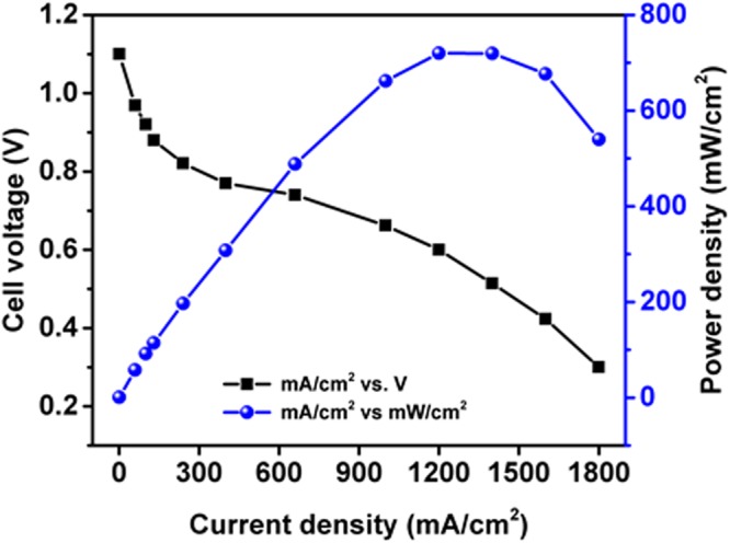
Single cell PEM fuel cell of J&M catalyst with PP substrate.
Conclusions
Structure property relations of ultra-low cost decal substrates have been scientifically evaluated for MEA fabrication in PEMFC. Across all substrates, PP films have shown 100% catalyst transferability. DSC studies indicate the PP substrate to be thermally stable at hot-press conditions and henceforth there is no poisoning of the catalyst layer. Catalyst ink has good wettability with PP films and exhibit uniform film forming capability. SEM imaging is done to study the surface characteristics of the electrode. Furthermore, the electrochemical studies confirm the performance of PP based MEAs to be on-par with commercial MEAs but at much reduced fabrication cost.
Materials
Nafion®212 polymer electrolyte membrane was obtained from Fuel cell store, Nafion solution (10 wt%)was obtained from Sainergy Fuel cell India PVT.LTD., Serpentine flow channel patterned, single cell PEMFC unit was obtained from Wonatech for Hydrogen-Oxygen test fixture. Carbon paper (Sigracet 35BC) used as gas diffusion layerwas imported from EWII Fuel Cells, 40 wt% Pt-C (Johnson Matthey Hispec-4000) from Sigma Aldrich, 2-propanol (99% purity) from Merck, Polypropylene was procured from Adhesive Specialities, Bangalore. Cellophane tape purchased from Super tape industries, Ahmedabad. Kapton (HN) was procured from Sigma Aldrich. Teflon, Reinforced PTFE procured from Polyfloro limited, Bengaluru. Silicon coated-polymer (Silicone coated PET) was purchased from Loparex India Private Limited, Mumbai. Deionized (DI) water was used throughout the experimentation.
Methods
Preparation of catalyst ink slurry
100 mg of JM catalyst was weighed. To it 500 µl water, 1500 µl isopropanol and 300 µl Nafion ionomer were added. The mixture was subjected to stirring for 60 minutes, sonication for 30 minutes and stirring again for 30 minutes.
Decal coating and MEA fabrication
The decal substrates were placed intact to the glass slide. The catalyst ink slurry was casted over the substrate and drag using a doctor blade with net 210 µm thickness. The catalyst coated decal was allowed to dry at room temperature overnight. The required active area size was cut and weighed before and after hot-press. The final loading of Platinum in the catalyst film was estimated to be 0.4 mg. cm−2. The coated substrate was cut to 5 cm2 active area and hot-press at 121 °C temperature, 75 kg.cm−2 pressure for 3 minutes. After hot-press the catalyst layerwas completely transferred over the membrane.
Contact angle measurements
Water played an important role in stability and dispersion of catalyst ink over the decal substrate29. Therefore, contact angle of the water on substrate studies were conducted using Olympus Polarizing microscope, model no. BX51TRF. The contact angle was measured by link sys integrated software with the instrument. Hydrophilic and hydrophobic analysis was carried on each substrate using contact angle measurement.
Calorimetric analysis
The temperature stability of each substrate was determined using Digital Scanning Calorimeter Mettler –Toledo, DSC 1 STARe system at a temperature ramp of 5 °C per minute from 30° to 300 °C and a nitrogen flow rate of 50 mL.min−1. All the curves were plotted on origin.
FTIR measurements
Fourier transform infrared spectroscopy was conducted to know the functional groups of the polymer with the instrument Bruker, Vertex-70/80. The films were placed between NaCl crystals and FTIR was recorded.
Electrochemical testing
All electrochemical evaluation was conducted using Biologic science instrument Model SP-150. The reactant gases were passed through wash bottles ensuring 100% relative humidity. The whole fuel cell set-up is kept in oven at 65 °C and atmospheric pressure. The mass flow of the reactant gases were controlled by Aalborg mass flow controller. The polarisation curves were studied from constant current and potential modes using built software in test station.
SEM analysis
FEI Quanta 200 Scanning electrode microscopy was used to investigate the surface electrode morphology of electrode and cross-section of catalyst coated membrane.
Catalyst layer transfer percentage
The catalyst layer transfer percentage of substrate was calculated using following equation
Thickness of the substrate
The thickness of the substrate was measured using thickness gauge instrument Mitutoyo thickness gauge.
Substrate poisoning
The thermal instability of the substrate during hot-press condition poisoned the catalyst that in turn degraded the performance of the MEA. This was referred as catalyst poisoning due to substrate and DSC was conducted to study the thermal stability of all the substrates.
Electronic supplementary material
Acknowledgements
All the authors fully thank Tata Chemicals Limited, Innovation Center, Pune, for providing the necessary infrastructure, logistics and support to carry out this entire work. The project is fully funded and has been completely carried at Tata Chemicals limited, Innovation Center, Pune. N.K.M expresses his gratitude on a personal note to Lord Krishna for his omnipresence and motivation. S.S.R.S. and S.H.A. thank on a personal note to Bhagawan Sri Sathya Sai Baba for his inspiration. All the authors thank Group Technology Innovation Office for their encouragement and support.
Author Contributions
S.H.A., E.D. and S.S.R.S. have conceived, streamlined and designed the experimentation. A.A. has helped throughout the course of experimentation. N.K.M. has guided and monitored the experimental progress with timely inputs. S.H.A. and D.E. have developed the Figures as well as written the manuscript. S.S.R.S. has edited and proof read the manuscript to facilitate enhanced readability.
Competing Interests
The authors declare no competing interests.
Footnotes
Publisher's note: Springer Nature remains neutral with regard to jurisdictional claims in published maps and institutional affiliations.
Electronic supplementary material
Supplementary information accompanies this paper at 10.1038/s41598-018-30215-0.
References
- 1.Paul S, Bhattacharya RN. Causality between energy consumption and economic growth in India: a note on conflicting results. Energy economics. 2004;26:977–983. doi: 10.1016/j.eneco.2004.07.002. [DOI] [Google Scholar]
- 2.U.S. Energy Information Administration, India’s economic growth is driving its energy consumption, https://www.eia.gov/todayinenergy/detail.php?id=10611 (2013).
- 3.Kamila S, et al. Highly Active 2D Layered MoS 2-rGO Hybrids for Energy Conversion and Storage Applications. Scientific reports. 2017;7:8378. doi: 10.1038/s41598-017-08677-5. [DOI] [PMC free article] [PubMed] [Google Scholar]
- 4.Scamman D, Newborough M, Bustamante H. Hybrid hydrogen-battery systems for renewable off-grid telecom power. International Journal of Hydrogen Energy. 2015;40:13876–13887. doi: 10.1016/j.ijhydene.2015.08.071. [DOI] [Google Scholar]
- 5.U. S. Department of Energy. Fuel Cells for Backup Power in Telecommunications Facilities. Hydrogen program, https://www.hydrogen.energy.gov/pdfs/44520.pdf (2009).
- 6.Noorden, R. V. In Nature News https://www.nature.com/news/liquid-storage-could-make-hydrogen-a-feasible-fuel-1.12518#/ref-link-2 (2013).
- 7.D. S Satyapal Fuel Cell Balance of Plant Introduction. https://energy.gov/sites/prod/files/2017/05/f34/fcto_bop_workshop_satyapal_0.pdf (2017).
- 8.Park K, Lee J, Kim H-M, Choi K-S, Hwang G. Discrete regenerative fuel cell reduces hysteresis for sustainable cycling of water. Scientific reports. 2014;4:4592. doi: 10.1038/srep04592. [DOI] [PMC free article] [PubMed] [Google Scholar]
- 9.Jayakumar A, Singamneni S, Ramos M, Al-Jumaily AM, Pethaiah SS. Manufacturing the Gas Diffusion Layer for PEM Fuel Cell Using a Novel 3D Printing Technique and Critical Assessment of the Challenges Encountered. Materials. 2017;10:796. doi: 10.3390/ma10070796. [DOI] [PMC free article] [PubMed] [Google Scholar]
- 10.Jeon Y, et al. Interface-designed membranes with shape-controlled patterns for high-performance polymer electrolyte membrane fuel cells. Scientific reports. 2015;5:16394. doi: 10.1038/srep16394. [DOI] [PMC free article] [PubMed] [Google Scholar]
- 11.Wang L, Advani SG, Prasad AK. Membrane electrode assembly with enhanced membrane/electrode interface for proton exchange membrane fuel cells. The Journal of Physical Chemistry C. 2013;117:945–948. doi: 10.1021/jp306887p. [DOI] [Google Scholar]
- 12.Thanasilp S, Hunsom M. Effect of MEA fabrication techniques on the cell performance of Pt–Pd/C electrocatalyst for oxygen reduction in PEM fuel cell. Fuel. 2010;89:3847–3852. doi: 10.1016/j.fuel.2010.07.008. [DOI] [Google Scholar]
- 13.Cho HJ, et al. Development of a novel decal transfer process for fabrication of high-performance and reliable membrane electrode assemblies for PEMFCs. international journal of hydrogen energy. 2011;36:12465–12473. doi: 10.1016/j.ijhydene.2011.06.113. [DOI] [Google Scholar]
- 14.Xie J, et al. The Ionomer Segregation in Composite Membrane Electrode Assemblies and the Effect on the Performance of Polymer Electrolyte Fuel Cells. J. Electrochem. SOC. 2003;7:151. [Google Scholar]
- 15.Irmawati Y et al. Preparation of catalyst coated membrane by modified decal transfer method for proton exchange membrane fuel cell in IOP Conference Series: Materials Science and Engineering. 223 (2017).
- 16.Shahgaldi S, Alaefour I, Unsworth G, Li X. Development of a low temperature decal transfer method for the fabrication of proton exchange membrane fuel cells. International Journal of Hydrogen Energy. 2017;42:11813–11822. doi: 10.1016/j.ijhydene.2017.02.127. [DOI] [Google Scholar]
- 17.Sasikumar G, Ihm J, Ryu H. Dependence of optimum Nafion content in catalyst layer on platinum loading. Journal of Power Sources. 2004;132:11–17. doi: 10.1016/j.jpowsour.2003.12.060. [DOI] [Google Scholar]
- 18.Passalacqua E, Lufrano F, Squadrito G, Patti A, Giorgi L. Nafion content in the catalyst layer of polymer electrolyte fuel cells: effects on structure and performance. Electrochimica Acta. 2001;46:799–805. doi: 10.1016/S0013-4686(00)00679-4. [DOI] [Google Scholar]
- 19.Sasikumar G, Ihm J, Ryu H. Optimum Nafion content in PEM fuel cell electrodes. Electrochimica Acta. 2004;50:601–605. doi: 10.1016/j.electacta.2004.01.126. [DOI] [Google Scholar]
- 20.Bhaskar Sompalli et al. Method of making fuel cell components including a catalyst layer and a plurality of ionomer overcoat layers, US20070213203A1 (2013).
- 21.Chiu MH, Prenner EJ. Differential scanning calorimetry: an invaluable tool for a detailed thermodynamic characterization of macromolecules and their interactions. Journal of Pharmacy and Bioallied Sciences. 2011;3:39. doi: 10.4103/0975-7406.76463. [DOI] [PMC free article] [PubMed] [Google Scholar]
- 22.PerkinElmer, I. Differential Scanning Calorimetry (DSC)-A Beginner’s Guide, https://www.perkinelmer.com/CMSResources/Images/44-74542GDE_DSCBeginnersGuide.pdf.
- 23.Young T., III An essay on the cohesion of fluids. Philosophical transactions of the royal society of London. 1805;95:65–87. doi: 10.1098/rstl.1805.0005. [DOI] [Google Scholar]
- 24.Yuan, Y. & Lee, T. R. Contact angle and wetting properties, Surface science techniques 3–34 Springer, (2013).
- 25.Zhang J, et al. Application of Fourier transform infrared spectroscopy with chemometrics on postmortem interval estimation based on pericardial fluids. Scientific reports. 2017;7:18013. doi: 10.1038/s41598-017-18228-7. [DOI] [PMC free article] [PubMed] [Google Scholar]
- 26.Pavia, D. L., Lampman, G. M. & Kriz, G. S. Introduction to spectroscopy. (ed. Thomas Brookers/cole)13–33 (2001).
- 27.Gulmine J, Janissek P, Heise H, Akcelrud L. Polyethylene characterization by FTIR. Polymer Testing. 2002;21:557–563. doi: 10.1016/S0142-9418(01)00124-6. [DOI] [Google Scholar]
- 28.Sundberg M, Månsson A, Tågerud S. Contact angle measurements by confocal microscopy for non-destructive microscale surface characterization. Journal of colloid and interface science. 2007;313:454–460. doi: 10.1016/j.jcis.2007.04.067. [DOI] [PubMed] [Google Scholar]
- 29.Huang DC, et al. Effect of dispersion solvent in catalyst ink on proton exchange 21 membrane fuel cell performance. Int. J. Electrochem. Sci. 2011;6:2551–2565. [Google Scholar]
Associated Data
This section collects any data citations, data availability statements, or supplementary materials included in this article.