

Abstract
Since its recent foundation, phase-coherent caloritronics has sparkled continuous interest giving rise to numerous concrete applications. This research field deals with the coherent manipulation of heat currents in mesoscopic superconducting devices by mastering the Josephson phase difference. Here, we introduce a new generation of devices for fast caloritronics able to control local heat power and temperature through manipulation of Josephson vortices, i.e., solitons. Although most salient features concerning Josephson vortices in long Josephson junctions were comprehensively hitherto explored, little is known about soliton-sustained coherent thermal transport. We demonstrate that the soliton configuration determines the temperature profile in the junction, so that, in correspondence of each magnetically induced soliton, both the flowing thermal power and the temperature significantly enhance. Finally, we thoroughly discuss a fast solitonic Josephson heat oscillator, whose frequency is in tune with the oscillation frequency of the magnetic drive. Notably, the proposed heat oscillator can effectively find application as a tunable thermal source for nanoscale heat engines and coherent thermal machines.
Introduction
In recent years, the growing demand of fast electronics promoted the thrive of applications based on Josephson vortices, i.e., solitons1–3. Nonetheless, the effective interplay between thermal transport and soliton dynamics is far from being fully explored. Indeed, the influence on the dynamics of solitons of a homogeneous temperature gradient applied along (namely, from one edge of the junction to the other) a long Josephson junctions (LJJs) was earlier studied, both theoretically and experimentally, in refs4–6. Instead, the issue of the soliton-sustained coherent thermal transport in a LJJ as a temperature gradient is imposed across the system (namely, as the electrodes forming the device reside at different temperatures) was exclusively recently addressed in refs7,8. The latter work reports the first endeavour to combine the physics of solitons and phase-coherent caloritronics9–12. This research field deals with the manipulation of heat currents in mesoscopic superconducting devices12–21 by mastering the phase difference of the superconducting order parameter. In this framework, the thermal modulation induced by the external magnetic field was first demonstrated in superconducting quantum-interference devices (SQUID)13,22 and then in short Josephson junctions (JJs)14,23. Moreover, hysteretic behaviours in temperature-biased Josephson devices were also recently discussed in refs24,25.
Although little is known about caloritronics effects in these systems, LJJs are still nowadays an active research field, both theoretically3,26–34 and experimentally2,35–42. In our work, we explore theoretically the effects of a sinusoidal magnetic drive on the thermal transport across a temperature-biased LJJ (see Fig. 1). We show that the behavior of solitons along the system is reflected on the fast evolution of both the heat power through the junction and the temperature of a cold “thermally floating” electrode of the device. Accordingly, we observe temperature peaks in correspondence of the magnetically induced solitons. Moreover, in sweeping back and forth the driving field, hysteretic thermal phenomena come to light. Finally, we thoroughly discuss the application of this system as a heat oscillator, in which the thermal flux flowing from the junction edge oscillates following the sinusoidal magnetic drive. The dynamical approach that we will address in this work, is essential to establish the performance and the figure of merits of the device, especially when a “fast” (with respect to the intrinsic thermalization time scale of the system) magnetic drive is considered.
Figure 1.
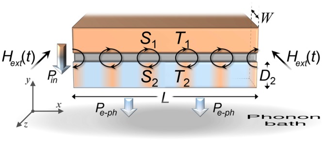
Fluxon chain in a magnetically driven, thermally biased LJJ. A S-I-S LJJ excited by an external in-plane magnetic field Hext(t). The length and the width of the junction are and , respectively, where is the Josephson penetration depth. Moreover, the thickness of the electrode S2 is indicated. A chain of fluxons, i.e., solitons, along the junction is depicted. The incoming, i.e., Pin (T1, T2, φ, V), and outgoing, i.e., Pe−ph (T2, Tbath), thermal powers in S2 are also represented, for T1 > T2(x) > Tbath.
Results
Theoretical modelling
We investigate the thermal transport in a temperature-biased long Josephson tunnel junction driven by the external magnetic field, Hext (t). The electrodynamics of a long and narrow Josephson tunnel junction is usually described by the perturbed sine-Gordon (SG) equation43
| 1 |
for the Josephson phase φ, namely, the phase difference between the wavefunctions describing the carriers in the superconducting electrodes. The time variations of φ generates a local voltage drop according to (where is the magnetic flux quantum, with e and h being the electron charge and the Planck constant, respectively). In previous equations, space and time variables are normalized to the Josephson penetration depth and to the inverse of the Josephson plasma frequency , respectively, i.e., and . The junction is called “long” just because its dimensions in units of are and (see Fig. 1). Here, we introduced the critical current density Jc, the effective magnetic thickness td = λL,1tanh (D1/2λL,1) + λL,2tanh (D2/2λL,2) + d14,23 (where λL,i and Di are the London penetration depth and the thickness of the electrode Si, respectively, and d is the insulating layer thickness), and the specific capacitance C of the junction due to the sandwiching of the superconducting electrodes. The dissipation in the junction is accounted by the damping parameter α = 1/(ωpRC), with R being the normal-state resistance per area of the junction44.
The unperturbed SG equation, i.e., α = 0 in equation (1), admits topologically stable travelling-wave solutions, called solitons45,46, corresponding to 2π-twists of the phase, which have the simple analytical expression43
| 2 |
the Josephson heat interferometer where σ = ±1 is the polarity of the soliton and u is the soliton velocity, measured in units of the Swihart’s velocity 43. A soliton has a clear physical meaning in the LJJ framework, since it carries a quantum of magnetic flux, induced by a supercurrent loop surrounding it, with the local magnetic field perpendicularly oriented with respect to the junction length. Thus, solitons in the context of LJJs are usually referred to as fluxons or Josephson vortices.
The effect on the phase evolution of the driving external magnetic field is accounted by the boundary conditions of equation (1),
| 3 |
The coefficient is called the first critical field of a LJJ47, since it is a threshold value above which, namely, for Hext (t) > Hc,1, in the absence of bias current solitons penetrate from the junction ends and fill the system with some density depending on both the value of H(t) and the length L of the junction.
The aim of this work is the investigation of the variations of the temperature T2 of the electrode S2 as the magnetic drive is properly swept. Specifically, the modulation of the temperature of the drain “cold” electrode is usually obtained by realizing a JJ with a large superconducting electrode, namely, S1, whose temperature T1 is kept fixed, and a smaller electrode, namely, S2, with a small volume and, thereby a small thermal capacity. In this way, the heat transferred significantly affects the temperature T2 of the latter electrode, which is then measured. For the sake of readability, hereafter we will adopt the abbreviated notation in which the x and t dependences are left implicit, namely, T2 = T2(x, t), φ = φ(x, t), and V = V(x, t). The electrode S2 can be modelled as a one-dimensional diffusive superconductor at a temperature varying along L, so that the evolution of the temperature T2 is given by the time-dependent diffusion equation7
| 4 |
where the term
| 5 |
consists of the phase-dependent incoming, i.e., , and the outgoing, i.e., , thermal power densities in S2. Finally, in equation (4), is the volume-specific heat capacity, with being the electronic entropy density of S216, and κ(T2) is the electronic heat conductivity19. We are assuming that the lattice phonons are very well thermalized with the substrate that resides at Tbath, thanks to the vanishing Kapitza resistance between thin metallic films and the substrate at low temperatures10,48. The full expressions and the physical meaning of all terms and coefficients in equations (4) and (5) are thoroughly discussed in ‘Methods’ section.
To explore the thermal transport in this system, it only remains to include in equation (4) the proper phase difference φ(x, t) for a LJJ given by numerical solution of equations (1) and (3), with initial conditions .
Numerical results
In the present study, we consider an Nb/AlOx/Nb SIS LJJ characterized by a normal resistance per area R = 50 Ω μm2 and a specific capacitance C = 50 f F/μm2. The linear dimensions of the junction are L = 100 μm for the length, W = 0.5 μm for the width, D2 = 0.1 μm and d = 1 nm for the thicknesses of S2 and the insulating layer, respectively.
For the Nb electrode, we assume , σN = 6.7 × 10⁶ Ω−1 m−1, Σ = 3 × 10⁹ Wm−3K−5, NF =1047 J−1m−3, Δ1(0) = Δ2(0) = Δ = 1.764kBTc, with Tc = 9.2 K being the common critical temperature of the superconductors, and γ1 = γ2 = 10−4Δ.
We impose a thermal gradient across the system, specifically, the bath resides at Tbath = 4.2 K, and S1 is at a temperature T1 = 7 K kept fixed throughout the computation. This value of the temperature T1 assures the maximal soliton-induced heating in S2, for a bath residing at the liquid helium temperature7. Nonetheless, the soliton-sustained local heating that we are going to discuss could be enhanced by reducing the bath temperature and correspondingly adjusting the temperature T1 of the hot electrode. However, we underline that a lowering of the working temperatures could lead to significantly longer thermal response times24.
The electronic temperature T2(x, t) of the electrode S2 is the key quantity to master the thermal transport across the junction, since it floats and can be driven by the external magnetic field. By including the proper temperature-dependence in both the effective magnetic thickness td (T1, T2) and the Josephson critical current density Jc (T1, T2), which varies with the temperatures according to the generalized Ambegaokar and Baratoff formula49,50, we obtain , , and . Moreover, corresponding to an underdamped dissipative regime. Anyway, these solitonic parameters weakly depend on the temperature T2, in the range of T2’s values that we will discuss.
We use a sinusoidal normalized driving field with frequency ωdr and maximum amplitude Hmax
| 6 |
so that H(t) within a half period is sweeping first forward from 0 to Hmax and then backward to 0. In the following, we impose Hmax = 5 and ωdr = 0.25 GHz, and we limit ourselves to investigate a single half period of the drive, corresponding to Tdr/2 = 4π ns. Anyway, since , we can image the presented solution for the phase profile as the adiabatic solution of the system. The evolution at multiple periods of the drive can be obtained by simply repeating the presented solution. Interestingly, a driving field sweeping back and forth is expected to give intriguing hysteretic behaviours51.
By increasing the magnetic field, for H(t) < 2, that means Hext(t) < Hc,1 according to equation (3), the junction is in the Meissner state, namely, the fluxon-free state of the system52,53. Instead, for a magnetic field above the critical value, i.e., for H(t) > 2, solitons in the form of fluxons penetrate the LJJ from its ends. However, in this case at a specific value of the magnetic field several solutions, describing distinct configurations with different amount of solitons, may concurrently exist51,53–55. The dynamical approach is essential to describe the JJ state when multiple solutions are available. In fact, when the magnetic field increases, at a certain point a configuration with more solitons can be energetically favorable and, thus, the system “jumps” from a metastable state to a more stable state. Therefore, the system stays in the present configuration until the following one is energetically more stable. The dynamical approach allows to determine both when the system switches and its new stable state.
The configurations of solitons are well depicted by the space derivative of the phase, , see Fig. 2, since it is proportional to the local magnetic field according to the relation43
| 7 |
The spatial distributions of at a few values of H, are shown in panels a and b of Fig. 2, as the driving field is swept first forward (solid lines) and then backward (dashed lines), respectively. The ripples in these curves indicate fluxons along the junction. For a large applied field the solitons are closely spaced, since the amount of fluxons, e.g., ripples, along the JJ increases by intensifying the magnetic field. In the forward dynamics, for H ≤ 2 the system is in the Meissner state, i.e., no ripples, meaning zero fluxons, and a decaying magnetic field penetrating the junction ends (see Fig. 2a). According to the nonlinearity of the problem, for higher fields (H > 2) the stable solutions are not the trivial superimposition of Meissner and vortex fields, but are rather solitons “dressed” by a Meissner field confined in the junction edges53. Hysteresis results looking at the local magnetic field during the backward sweeping of the drive, see Fig. 2b. In fact, we observe that forward and backward spatial distributions of clearly differ, inasmuch as solitons still persist by reducing the driving field. Nevertheless, for H(t) = 0 no solitons actually remain within the system in both forward and backward dynamics. This hysteretical behavior comes from the multistability of the SG model33,51,53–56. In fact, Kuplevakhsky and Glukhov demonstrated that each solution of the SG equation, with a distinct number of solitons, is stable in a broad range of magnetic field values53–55. Besides, they observed that these stability regions tend to overlap. Essentially, it means that at a fixed value of the magnetic field different stable solutions, with different amount of solitons along the system, may concurrently exists. Furthermore, it was demonstrated that the longer the junction, the stronger the overlap, and that overlapping decreases by increasing the magnetic field53. This fact not only ensures that the stable solutions cover the whole field range 0 ≤ H < ∞, but also proves that hysteresis is an intrinsic property of any LJJ53. The evolution of a magnetically driven system described by the SG equation can be understood by analyzing the Gibbs free-energy functional and its minimization51,53–55,57,58. In fact, by sweeping the magnetic field, the system stays in a current state until the following one is energetically more stable. In this case the system “jumps” from a metastable state to a more stable one with a different configuration of solitons. Interestingly, the hysteresis and the sudden transitions between states with different number of solitons slightly depend also on the damping parameter51.
Figure 2.

Soliton configurations as a function of the magnetic drive. Space derivative of the phase, , as a function of x at those times at which the normalized driving field assumes the values H(t) = {0,1,2,3,4,5} during the forward [solid lines, panel a] and backward [dashed lines, panels b] sweeps of the drive. In panels c and d, the evolutions of and H(t) are shown, respectively. In the latter panels, the horizontal, red solid and dashed lines indicate the times at which the curves in panels a and b are calculated, respectively.
The full spatio-temporal evolution of the space derivative of φ is displayed in the contour plot in Fig. 2c. Alongside, the time evolution of the magnetic drive is shown, see Fig. 2d. In both panels, horizontal red solid and dashed lines indicate the times at which the curves in panels a and b are calculated, respectively. In Fig. 2c, dark fringes patterns along x indicate solitons along the junction. Furthermore, this figure discloses the transitions between different stable states, when the amount of solitons along the junction changes. As the magnetic field is increased (decreased) the solitons are shifted towards (away from) the center of the junction up to a pair of solitons is symmetrically injected (extracted) from the junction ends. Moreover, we observe that solitons arrange symmetrically and equidistantly along the junction, since the system is centrosymmetric and the solitons with the same polarity tend to repel each other.
We have seen that the investigation of the full dynamics is crucial to understand the junction behavior, which depends on the full evolution of the system51. Therefore, it is natural to wonder if also the heat transport throughout the system, and then the temperature of the junction, changes with the history of the system and how it is related to the soliton evolution.
The time and space evolution of the heat power Pin flowing from S1 to S2 is shown in the density plot in Fig. 3. In the abscisses of this figure we report the position along the LJJ, whereas on the left we show the time and the corresponding values of the magnetic field are shown on the right. We observe that solitons locally correspond to clearly enhancements of the heat power Pin, namely, the heat current flowing through the junction is significantly supported by a magnetically excited soliton. In fact, the value of the heat power in correspondence of each soliton is , namely, a value three times higher than the power flowing elsewhere. The configurations of solitons, the sudden transitions between stable states with different amount of solitons, and the hysteretical behavior by sweeping back and forth the driving field are noticeable in Fig. 3.
Figure 3.
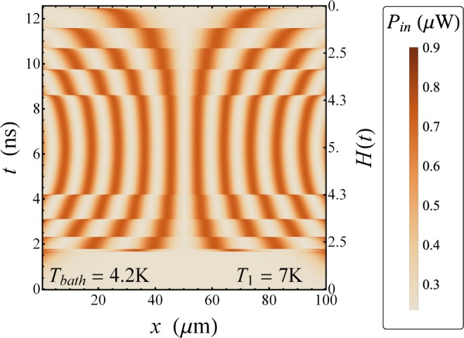
Phase dependent heat power. Evolution of the heat power Pin (x, t) at T1 = 7 K and Tbath = 4.2 K, for Hmax = 5 and ωdr = 0.25 GHz.
Finally, the behaviour of the temperature T2 reflects the behavior of the thermal power Pin, as it is shown in Fig. 4. In panel a of this figure, we observe that when a transition between stable states occurs, the temperature exhibits a locally peaked behavior. We observe that as a soliton set in, it induces a local intense warming-up in S2, so that the temperature of the system locally rapidly approaches the maximum value . Then, when a change in the magnetic field causes a transition to occur, the soliton positions modifies and the temperature adapts to this variation. In fact, the temperature peaks shift according to the new configuration of solitons, see Fig. 4a. In this way, for H = Hmax several peaks compose the temperature profile, one for each soliton induced by the magnetic field. The contour plot in Fig. 4b gives a clear image of the spatio-temporal distribution of T2. In this figure, it is evident how the temperature accurately follows the solitonic dynamics. We note that, for the backward drive, for two temperature peaks persist, although in the Meissner state (i.e., H < 2 during the forward sweep of the drive) the whole electrode S2 if roughly thermalized at the same temperature. This thermal hysteresis is evidently highlighted in Fig. 5, for H(t) = 0.5 as the driving field is swept first forward (solid line) and then backward (dashed line).
Figure 4.

Temperature evolution. Evolution of the temperature T2(x, t) of the floating electrode S2 at T1 = 7 K and Tbath = 4.2 K, for Hmax = 5 and ωdr = 0.25 GHz. The legend refers to both panels.
Figure 5.
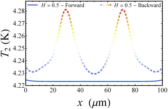
Thermal hysteresis. Hysteretic behaviour of the temperature T2 along the junction for H(t) = 0.5 as the driving field is swept first forward (solid line) and then backward (dashed line).
The results discussed in this work could promptly find application in different contexts. For instance, an alternative method of fluxon imaging in extended JJs could be conceived. Heretofore, the low temperature scanning electron microscopy (LTSEM)59–61 was confirmed to be an efficient experimental tool for studying fluxon dynamics in Josephson devices. In this technique, a narrow electron beam is used to locally heat a small portion (~μm) of the junction, in order to locally increase the effective damping parameter. Consequently, the I-V characteristic of the device changes, so that, by gradually moving the electron beam along the junction surface and measuring the voltage, a sort of image of the dynamical state of the LJJ can be created. In our work, we demonstrated that, by imposing a thermal gradient across the junction, the temperature profile of the floating electrode mimics the positions of magnetically-induced solitons. Therefore, our findings can be effectively used for a thermal imaging of steady solitons in LJJs through calorimetric measurements62–66. Moreover, the dynamics discussed so far embodies the thermal router application suggested in ref.7. In fact, we can image a superconducting finger attached in a specific point of S2. Then, by adjusting the external magnetic field, we can induce a specific configuration of solitons along the junction, such to magnetically excite a soliton exactly in correspondence of this finger, with the aim to allow the route of the heat throughout this thermal channel. Finally, this device can be used to design a solid-state heat oscillator actively controlled by a magnetic drive. The latter application is carefully discussed in the following section.
The Josephson heat oscillator
We observe that the sinusoidal magnetic field causes the temperature of both sides of the junction to oscillate, and that, for H = 2, only two solitons are penetrating the junction, with the center of the solitons being exactly located at the junction edges in x = {0, L} (see Fig. 2a). Let us now discuss the temperature response through the solitonic dynamics. For H = 2 we have in x = {0, L} the maximum temperature enhancement, since this is the only case in which we can definitively assume a soliton firmly set in a junction end. In fact, the situations for 0 < H < 2 can be envisaged by depicting two solitons situated outside the junction, so that by increasing the value of H the solitons moves closer to the junction edges, until their centers are on the borders of junction in x = {0, L} for H = 2. Instead, for higher fields, i.e., H > 2, solitons start to penetrate (leave) the junction, so that the temperature of each edge nonlinearly follows the abrupt magnetically driven processes of injection (extraction) of solitons. In light of these remarks, we conceive a heat oscillator based on a temperature biased LJJ driven by a sinusoidal magnetic field with Hmax = 2. Specifically, we design to handle the temperature of the right edge of S2, i.e., in x = L, with the aim to generate and master a thermal power Ploss, which flows from the right side of S2, see Fig. 6, which oscillates according to the magnetic drive.
Figure 6.
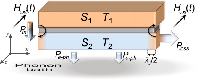
Magnetically driven long junction operating as a Josephson heat oscillator. Thermal fluxes in a temperature biased LJJ driven by a sinusoidal magnetic flux, see equation 6, with Hmax = 2. Two solitons confined at the junction edges for H = Hmax are also depicted. Besides the incoming and outgoing thermal powers in S2, the thermal power loss Ploss flowing from the right side of S2 is also represented.
We first discuss the effects produced by the variations of both the driving amplitude and the frequency on the temperature T2(x = L, t) when a negligible loss thermal power is assumed, i.e., Ploss = 0, and then how Ploss affects this temperature.
The modulation of the temperature of S2 due to a sinusoidal drive with Hmax = 2 and ωdr = 0.5 GHz, for Ploss = 0, is displayed in Fig. 7a. This figure shows that the enhancement of the temperature is restricted to the junction edges, since for H ≤ 2 there are no solitons inside the system. Moreover, the temperature we are interested in, namely, the temperature of the junction edge in x = L, oscillates in tune with the driving field. Specifically, T2(L, t) shows peaks for |H(t)| = Hmax, namely, for t = Tdr/4 and t = 3Tdr/4 (with Tdr being the driving period), and minima for H(t) = 0. This means that, the thermal oscillation frequency is twice the driving frequency, since the thermal effects are independent on the polarity of the soliton. Accordingly, the frequency requirements of this device are less demanding. This phenomenon allows to discriminate in frequency the magnetic drive from the thermal oscillation.
Figure 7.

Thermal oscillations as a function of the magnetic drive. (a) Evolution of the temperature T2(x, t) of the floating electrode S2 at T1 = 7 K and Tbath = 4.2 K, for Hmax = 2, ωdr = 0.5 GHz, and Ploss = 0. (b) T2(x, t) as a function of t for x = L at a few values of Hmax∈[0.2−2] for ωdr = 0.25 GHz. (c–g) T2(x, t) as a function of t for x = L, at a few values of ωdr for Hmax = 2.
Clearly, the oscillatory behavior of the edge temperature T2(L, t) persists also by reducing Hmax, see Fig. 7b for ωdr = 0.25 GHz, although the maximum value of the temperature reduces with decreasing the maximum magnetic drive. The position of the temperature peak is however independent on Hmax, as it is well demonstrated in Fig. 7b. Alternatively, in Fig. 7c–g the behavior of the temperature T2(L, t) for Hmax = 2 at a few values of ωdr is shown. We note that the temperature oscillation amplitude is drastically damped by increasing the driving frequency, even if the value around which the temperature oscillates is independent on ωdr. Since the coherent thermal transport is a nonlinear phenomenon, we note that the frequency purity is affected by small corrections inducting vanishingly small spectral components at frequency ωdr. This effect can be observed as a small beat in the time evolution of T2 (e.g. see Fig. 7e).
The behavior of the system can be clearly outlined by the T2 modulation amplitude, δT2, defined as the difference between the maximum and the minimum values of T2(L, t) within an oscillation of the drive. In fact, we can define two relevant figures of merit of the thermal oscillator, represented by the modulation amplitude, δT2, as a function of both the driving frequency ωdr (see Fig. 8a, for Hmax = 2 and Ploss = 0) and the maximum driving amplitude Hmax (see Fig. 8b, for ωdr = 0.25 GHz and Ploss = 0).
Figure 8.

Figures of merit of the Josephson heat oscillator. Relevant figures of merit of the heat oscillator, represented by the modulation amplitude, δT2, as a function of the driving frequency ωdr (for Hmax = 2 and Ploss = 0), the maximum driving amplitude Hmax (for ωdr = 0.25 GHz and Ploss = 0), and the loss thermal conductance η (for Hmax = 2 and ωdr = 0.25 GHz), see (a, b and c), respectively. In panel a a fitting curve is also shown.
We look first at the behaviour of δT2 by varying the driving frequency ωdr (see Fig. 8a). We observe that δT2 is roughly constant for , specifically, . For higher frequencies, the modulation amplitude reduces, going down linearly in the semi-log plot shown in Fig. 8a. In fact, as the thermal oscillation frequency becomes comparable to the inverse of the characteristic time scale for the thermal relaxation processes, the temperature is not able to follow the fast driving field. According to ref.25, this thermal response time can be defined as the characteristic time of the exponential evolution by which the temperature locally approaches its stationary value in the presence of a soliton. In ref.7, for a Nb based junction at the same working temperatures used in this work, a thermal response time roughly equal to was estimated. The modulation amplitude at driving frequency ωdr rolls off as (1 + (2ωdrτth)2)−1/2 since τth determines the time scale of the energy exchange between the ensemble and reservoir. Then, by fitting the δT2(ωdr) data with the curve the parameters δT2,0 = (55.87 ± 0.08) mK and τfit = (0.243 ± 0.001) ns are estimated (see dashed curve in Fig. 8a). For higher frequencies, other nonlinear effects, related to the finite size of the system, can play a role. Anyway, we are dealing with a regime of tiny temperature modulations at very high frequencies, which is not so significative for practical points of view.
In Fig. 8b the behavior of δT2 as a function of Hmax, for ωdr = 0.25 GHz, is shown. We observe that, by increasing the maximum drive, the T2 modulation amplitude grows more than linearly. This behavior represents a sort of calibration curve for the thermal oscillator.
Now, we assume a non-vanishing thermal power Ploss flowing throughout the right side of S2, which area is A = WD2. For simplicity, we speculate that this thermal power might depend linearly on the temperature T2(L, t) according to
| 8 |
In this equation, η is a thermal conductance, measured in W/K, that we use as knob to emulate the thermal effectiveness of the load. Thus, another figure of merit of the heat oscillator can be delineated by the T2 modulation amplitude as a function of the coupling constant η, see Fig. 8c for Hmax = 2 and ωdr = 0.25 GHz. From this figure we note that δT2 is roughly constant for low values of η, and that the energy outgoing from the right side of S2 affects the temperature of T2 only for . Above this value, the modulation temperature significantly reduces, going to zero for .
To estimate the coupling constant threshold value, ηcr,1, above which δT2 starts to reduce, we use a scaling argument based on the boundary condition derived by the Fourier law throughout the area A and assuming a temperature drop δT2 also along a distance . Accordingly, we obtain
| 9 |
from which .
Differently, the value of the critical coupling constant ηcr,2 at witch δT2 → 0 can be estimated by supposing that the incoming thermal power due to a soliton is entirely balanced by the outgoing power flowing towards both the thermal bath and the right side of S2. We assume that the thermal power induced by a soliton centered in x = L flows through a volume . Then, at the equilibrium, from equation (8), we obtain
| 10 |
where and are the electron-phonon25,67 and electron14,25 thermal conductances, in unit volume, (see “Methods” section), and T2, s is the steady temperature in x = L. For T2,s = 4.23 K, we obtain .
It is worth noting that the specifications of the proposed thermal oscillator can be tuned by properly choosing the system parameters. For instance, the modulation amplitude could be enhanced by lowering the temperature of the phonon bath and accordingly adjusting the temperature of the hot electrode. Furthermore, the use of superconductors with higher Tc’s gives higher thermalization frequencies, and then it permits to push forward the frequency threshold below which no attenuations of δT2 occur.
The proposed heat oscillator could find application as a temperature controller for heat engines68–72. In fact, in mesoscale and nanoscale systems the precise control of the temperature in a fast time scale is regarded as a difficulty to cope with. Thus, through this system we could be able to definitively master the temperature, which oscillates in a controlled way by a fast magnetic drive. Accordingly, we can envision to build nanoscale heat motors or thermal cycles based on this Josephson heat oscillator.
In summary, in this paper we have thoroughly investigated the effects produced by a time-dependent driving magnetic field on the temperature profile of a long Josephson junction, as a thermal gradient across the system is imposed. A proper magnetic drive induces Josephson vortices, i.e., solitons, along the junction. We showed that the soliton configuration is reflected first on the distribution of heat power flowing through the system and then on the temperature of a cold electrode of the device. In fact, we demonstrated a multipeaked temperature profile, due to the local warming-up of the junction in correspondence of each magnetically excited soliton. Moreover, the study of the full evolution of the system disclosed a clear thermal hysteretic effect as a function of the magnetic drive. We explored a realistic Nb-based setup, where the temperature of the “hot” electrode is kept fixed and the thermal contact with a phonon bath at Tbath = 4.2 K is taken into account. Nevertheless, the soliton-induced heating that we observed can be increased by reducing the temperature of the phonon bath and manipulate by properly control the magnetic drive.
Finally, we discussed the implementation of a heat oscillator based on this system. In the Meissner state, H < Hc,1, the magnetic drive affects significantly the phase at the junction edges. In these locations, a clear temperature enhancement is observed. Thus, a sinusoidal external magnetic field, with maximum value equal to Hc,1, causes the edges temperature to oscillate with a frequency twice than the driving field one. This phenomenon can be used to conceive a low temperature, field-controlled heat oscillator device based on the thermal diffusion in a Josephson junction, for creating an oscillating heat flux from a spatial thermal gradient between the warm electrode and a cold reservoir, i.e. the phonon bath. The thermal oscillator may have numerous applications, inasmuch as the creation and utilization of an alternating heat flux is applicable to technical systems operating in response to periodic temperature variations, like heat engines, energy-harvesting devices, sensing devices, switching devices, or clocking devices for caloritronics circuits and thermal logic. Additionally, through proper figures of merit, we discussed the behavior of this heat oscillator by varying both the frequency and the amplitude of the driving field, and also by assuming a non-vanishing loss power flowing towards a thermal load. Especially in this context, the dynamical, i.e., fully time-dependent, approach that we used is crucial to understand how the system thermally responds to a fast magnetic drive. For instance, we observed that when the driving frequency becomes comparable to the inverse of the thermalization characteristic times25, the system is no longer able to efficiently follow the drive and the modulation range of the temperature accordingly reduces.
Methods
Thermal Powers
In the adiabatic regime, the contributes, in unit volume, to the energy transport in a temperature-biased JJ read73
| 11 |
| 12 |
| 13 |
where , is the Fermi distribution function, is the reduced superconducting density of state, with Δj(Tj) and γj being the BCS energy gap and the Dynes broadening parameter74 of the j-th electrode, respectively.
These equations derives from processes involving both Cooper pairs and quasiparticles in tunneling through a JJ predicted by Maki and Griffin9. In fact, is the heat power density carried by quasiparticles, namely, it is an incoherent flow of energy through the junction from the hot to the cold electrode9,10. Instead, the “anomalous” terms and determine the phase-dependent part of the heat transport originating from the energy-carrying tunneling processes involving Cooper pairs and recombination/destruction of Cooper pairs on both sides of the junction.
We note that , in the temperature regimes we are taking into account, is vanishingly small with respect to both and contributions, and it can be, in principle, neglected. Moreover, since this term depends on the time derivative of the phase, it could be effective only when the phase rapidly changes, namely, when the soliton enter, or escape, the junction. However, the timescale of the soliton evolution is definitively shorter than the timescales of the driving processes. Consequently, the soliton phase profile follows adiabatically the driving induced by the magnetic field. In this condition, if the number of trapped solitons along the junction is fixed the time scale evolution of the phase is given by the driving process. Anyway, we stress that equation (13) is a purely reactive contributions73,75, so that in the thermal balance equation (4) we have to neglect it. Therefore, the total thermal power density to include in Eq. (5) reads
| 14 |
The latter term of the rhs of equation (5), i.e., , represents the energy exchange, in unit volume, between electrons and phonons in the superconductor and reads76
| 15 |
where , , Σ is the electron-phonon coupling constant, and ζ is the Riemann zeta function.
Finally, in equation (4), is the volume-specific heat capacity, with being the electronic entropy density of S216
| 16 |
and κ(T2) is the electronic heat conductivity19
| 17 |
with σN and NF being the electrical conductivity in the normal state and the density of states at the Fermi energy, respectively.
The first derivative of the heat power densities in equation (5), calculated at a steady electronic temperature Te, gives the electron-phonon thermal conductance67, in unit volume,
| 18 |
and the electron thermal conductance14, in unit volume,
| 19 |
where .
To estimate ηcr,2 through equation (10), we assume φ = π in equation (19), since the center of the soliton, in correspondence of which φ = π, is placed exactly in the junction edge x = L.
Acknowledgements
We acknowledge P. Virtanen for fruitful discussions. C.G., A.B., and F.G. acknowledge the European Research Council under the European Union’s Seventh Framework Program (FP7/2007-2013)/ERC Grant agreement No. 615187-COMANCHE and the Tuscany Region under the PAR FAS 2007-2013, FAR-FAS 2014 call, project SCIADRO, for financial support. P.S. and A.B. have received funding from the European Union FP7/2007-2013 under REA Grant agreement No. 630925 – COHEAT. A.B. acknowledges the CNR-CONICET cooperation programme “Energy conversion in quantum nanoscale hybrid devices” and the Royal Society though the International Exchanges between the UK and Italy (grant IES R3 170054).
Author Contributions
C.G., P.S., A.B. and F.G. conceived the ideas and designed the study. C.G. developed the algorithm and carried out the simulations. C.G., P.S., A.B. and F.G. discussed the results and wrote the paper.
Competing Interests
The authors declare no competing interests.
Footnotes
Publisher's note: Springer Nature remains neutral with regard to jurisdictional claims in published maps and institutional affiliations.
References
- 1.Anders S, et al. European roadmap on superconductive electronics–status and perspectives. Physica C: Superconductivity. 2010;470:2079–2126. doi: 10.1016/j.physc.2010.07.005. [DOI] [Google Scholar]
- 2.Likharev KK. Superconductor digital electronics. Physica (Amsterdam) 2012;482C:6–18. [Google Scholar]
- 3.Wustmann, W. & Osborn, K. D. Reversible fluxon logic: Topological particles allow gates beyond the standard adiabatic limit. arXiv preprint arXiv:1711. 04339 (2018).
- 4.Logvenov G, Vernik I, Goncharov M, Kohlstedt H, Ustinov A. Dynamics of Josephson vortices in a temperature gradient. Phys. Lett. A. 1994;196:76–82. doi: 10.1016/0375-9601(94)91047-2. [DOI] [Google Scholar]
- 5.Golubov AA, Logvenov GY. Motion of a Josephson vortex under a temperature gradient. Phys. Rev. B. 1995;51:3696–3700. doi: 10.1103/PhysRevB.51.3696. [DOI] [PubMed] [Google Scholar]
- 6.Krasnov VM, Oboznov VA, Pedersen NF. Fluxon dynamics in long Josephson junctions in the presence of a temperature gradient or spatial nonuniformity. Phys. Rev. B. 1997;55:14486–14498. doi: 10.1103/PhysRevB.55.14486. [DOI] [Google Scholar]
- 7.Guarcello C, Solinas P, Braggio A, Giazotto F. Solitonic Josephson thermal transport. Phys. Rev. Applied. 2018;9:034014. doi: 10.1103/PhysRevApplied.9.034014. [DOI] [Google Scholar]
- 8.Guarcello, C., Solinas, P., Braggio, A. & Giazotto, F. Solitonic thermal transport in a current biased long josephson junction. arXiv preprint arXiv:1805.05685 (2018).
- 9.Maki K, Griffin A. Entropy transport between two superconductors by electron tunneling. Phys. Rev. Lett. 1965;15:921–923. doi: 10.1103/PhysRevLett.15.921. [DOI] [Google Scholar]
- 10.Giazotto F, Heikkilä TT, Luukanen A, Savin AM, Pekola JP. Opportunities for mesoscopics in thermometry and refrigeration: Physics and applications. Rev. Mod. Phys. 2006;78:217–274. doi: 10.1103/RevModPhys.78.217. [DOI] [Google Scholar]
- 11.Martínez-Pérez MJ, Solinas P, Giazotto F. Coherent caloritronics in Josephson-based nanocircuits. J. Low Temp. Phys. 2014;175:813–837. doi: 10.1007/s10909-014-1132-6. [DOI] [Google Scholar]
- 12.Fornieri A, Giazotto F. Towards phase-coherent caloritronics in superconducting circuits. Nat. Nanotechnology. 2017;12:944–952. doi: 10.1038/nnano.2017.204. [DOI] [PubMed] [Google Scholar]
- 13.Giazotto F, Martnez-Pérez MJ. The Josephson heat interferometer. Nature. 2012;492:401–405. doi: 10.1038/nature11702. [DOI] [PubMed] [Google Scholar]
- 14.Martnez-Pérez MJ, Giazotto F. A quantum diffractor for thermal flux. Nat. Commun. 2014;5:3579. doi: 10.1038/ncomms4579. [DOI] [PubMed] [Google Scholar]
- 15.Martnez-Pérez MJ, Fornieri A, Giazotto F. Rectification of electronic heat current by a hybrid thermal diode. Nature Nanotechnology. 2015;10:303–307. doi: 10.1038/nnano.2015.11. [DOI] [PubMed] [Google Scholar]
- 16.Solinas P, Bosisio R, Giazotto F. Microwave quantum refrigeration based on the Josephson effect. Phys. Rev. B. 2016;93:224521. doi: 10.1103/PhysRevB.93.224521. [DOI] [Google Scholar]
- 17.Fornieri A, Blanc C, Bosisio R, D’Ambrosio S, Giazotto F. Nanoscale phase engineering of thermal transport with a Josephson heat modulator. Nat. Nanotechnology. 2016;11:258–262. doi: 10.1038/nnano.2015.281. [DOI] [PubMed] [Google Scholar]
- 18.Paolucci F, Marchegiani G, Strambini E, Giazotto F. Phase-tunable temperature amplifier. EPL (Europhysics Letters) 2017;118:68004. doi: 10.1209/0295-5075/118/68004. [DOI] [Google Scholar]
- 19.Fornieri A, Timossi G, Virtanen P, Solinas P, Giazotto F. 0–π phase-controllable thermal Josephson junction. Nat. Nanotechnology. 2017;12:425–429. doi: 10.1038/nnano.2017.25. [DOI] [PubMed] [Google Scholar]
- 20.Paolucci, F., Marchegiani, G., Strambini, E. & Giazotto, F. Phase-tunable thermal logic: computation with heat. Phys. Rev. Applied 10, 024003 (2018)
- 21.Timossi GF, Fornieri A, Paolucci F, Puglia C, Giazotto F. Phase-tunable Josephson thermal router. Nano Letters. 2018;18:1764–1769. doi: 10.1021/acs.nanolett.7b04906. [DOI] [PubMed] [Google Scholar]
- 22.Giazotto F, Martnez-Pérez MJ. Phase-controlled superconducting heat-flux quantum modulator. Appl. Phys. Lett. 2012;101:102601. doi: 10.1063/1.4750068. [DOI] [Google Scholar]
- 23.Giazotto F, Martnez-Pérez MJ, Solinas P. Coherent diffraction of thermal currents in Josephson tunnel junctions. Phys. Rev. B. 2013;88:094506. doi: 10.1103/PhysRevB.88.094506. [DOI] [Google Scholar]
- 24.Guarcello C, Solinas P, Di Ventra M, Giazotto F. Hysteretic superconducting heat-flux quantum modulator. Phys. Rev. Applied. 2017;7:044021. doi: 10.1103/PhysRevApplied.7.044021. [DOI] [Google Scholar]
- 25.Guarcello C, Solinas P, Braggio A, Di Ventra M, Giazotto F. Josephson thermal memory. Phys. Rev. Applied. 2018;9:014021. doi: 10.1103/PhysRevApplied.9.014021. [DOI] [Google Scholar]
- 26.Gulevich DR, Kusmartsev F. New phenomena in long Josephson junctions. Supercond. Sci. Technol. 2007;20:S60. doi: 10.1088/0953-2048/20/2/S13. [DOI] [Google Scholar]
- 27.Monaco R. Magnetic sensors based on long Josephson tunnel junctions. Supercond. Sci. Technol. 2012;25:115011. doi: 10.1088/0953-2048/25/11/115011. [DOI] [Google Scholar]
- 28.Valenti D, Guarcello C, Spagnolo B. Switching times in long-overlap Josephson junctions subject to thermal fluctuations and non-Gaussian noise sources. Phys. Rev. B. 2014;89:214510. doi: 10.1103/PhysRevB.89.214510. [DOI] [Google Scholar]
- 29.Guarcello C, Valenti D, Carollo A, Spagnolo B. Stabilization effects of dichotomous noise on the lifetime of the superconducting state in a long Josephson junction. Entropy. 2015;17:2862. doi: 10.3390/e17052862. [DOI] [Google Scholar]
- 30.Zelikman MA. Hysteresis in the behavior of a long modulated Josephson junction in a magnetic field for small values of the pinning parameter. Technical Physics. 2015;60:1299–1304. doi: 10.1134/S1063784215090261. [DOI] [Google Scholar]
- 31.Pankratov AL, Fedorov KG, Salerno M, Shitov SV, Ustinov AV. Nonreciprocal transmission of microwaves through a long Josephson junction. Phys. Rev. B. 2015;92:104501. doi: 10.1103/PhysRevB.92.104501. [DOI] [Google Scholar]
- 32.Guarcello C, Valenti D, Carollo A, Spagnolo B. Effects of Lévy noise on the dynamics of sine-Gordon solitons in long Josephson junctions. J. Stat. Mech.: Theory Exp. 2016;2016:054012. doi: 10.1088/1742-5468/2016/05/054012. [DOI] [Google Scholar]
- 33.Guarcello C, Solinas P, Di Ventra M, Giazotto F. Solitonic Josephson-based meminductive systems. Sci. Rep. 2017;7:46736. doi: 10.1038/srep46736. [DOI] [PMC free article] [PubMed] [Google Scholar]
- 34.D. Hill, S. K. Kim, and Y. Tserkovnyak, Spin-Torque-Biased Magnetic Strip: Nonequilibrium Phase Diagram and Relation to Long Josephson Junctions, Phys. Rev. Lett.121, 037202 (2018). [DOI] [PubMed]
- 35.Ooi S, et al. Nonlinear nanodevices using magnetic flux quanta. Phys. Rev. Lett. 2007;99:207003. doi: 10.1103/PhysRevLett.99.207003. [DOI] [PubMed] [Google Scholar]
- 36.Fedorov KG, Shitov SV, Rotzinger H, Ustinov AV. Nonreciprocal microwave transmission through a long Josephson junction. Phys. Rev. B. 2012;85:184512. doi: 10.1103/PhysRevB.85.184512. [DOI] [Google Scholar]
- 37.Monaco R, Granata C, Russo R, Vettoliere A. Ultra-low-noise magnetic sensing with long Josephson tunnel junctions. Supercond. Sci. Technol. 2013;26:125005. doi: 10.1088/0953-2048/26/12/125005. [DOI] [Google Scholar]
- 38.Granata C, Vettoliere A, Monaco R. Noise performance of superconductive magnetometers based on long Josephson tunnel junctions. Supercond. Sci. Technol. 2014;27:095003. doi: 10.1088/0953-2048/27/9/095003. [DOI] [Google Scholar]
- 39.Koshelets VP. Sub-terahertz sound excitation and detection by a long Josephson junction. Supercond. Sci. Technol. 2014;27:065010. doi: 10.1088/0953-2048/27/6/065010. [DOI] [Google Scholar]
- 40.Fedorov KG, Shcherbakova AV, Wolf MJ, Beckmann D, Ustinov AV. Fluxon readout of a superconducting qubit. Phys. Rev. Lett. 2014;112:160502. doi: 10.1103/PhysRevLett.112.160502. [DOI] [PubMed] [Google Scholar]
- 41.Vettoliere A, Granata C, Monaco R. Long Josephson junction in ultralow-noise magnetometer configuration. IEEE Trans. Magn. 2015;51:1–4. doi: 10.1109/TMAG.2014.2357473. [DOI] [Google Scholar]
- 42.Golovchanskiy IA, et al. Ferromagnetic resonance with long Josephson junction. Supercond. Sci. Technol. 2017;30:054005. doi: 10.1088/1361-6668/aa66a9. [DOI] [Google Scholar]
- 43.Barone, A. & Paternò, G. Physics and Applications of the Josephson Effect (Wiley, New York, 1982).
- 44.Tinkham, M. Introduction to Superconductivity: Second Edition. Dover Books on Physics (Dover Publications, 2004).
- 45.Parmentier, R. D. Solitons and Long Josephson Junctions, 221–248 (Springer Netherlands, Dordrecht, 1993).
- 46.Ustinov AV. Solitons in Josephson junctions. Physica D. 1998;123:315–329. doi: 10.1016/S0167-2789(98)00131-6. [DOI] [Google Scholar]
- 47.Goldobin, E. Flux-flow oscillators and phenomenon of Cherenkov radiation from fast moving fluxons. In Microwave Superconductivity, 581–614 (Springer, 2001).
- 48.Wellstood FC, Urbina C, Clarke J. Hot-electron effects in metals. Phys. Rev. B. 1994;49:5942–5955. doi: 10.1103/PhysRevB.49.5942. [DOI] [PubMed] [Google Scholar]
- 49. Giazotto, F. & Pekola, J. P. Josephson tunnel junction controlled by quasiparticle injection. J. Appl. Phys. 97 (2005).
- 50.Bosisio R, Solinas P, Braggio A, Giazotto F. Photonic heat conduction in Josephson-coupled Bardeen-Cooper-Schrieffer superconductors. Phys. Rev. B. 2016;93:144512. doi: 10.1103/PhysRevB.93.144512. [DOI] [Google Scholar]
- 51.Guarcello C, Giazotto F, Solinas P. Coherent diffraction of thermal currents in long Josephson tunnel junctions. Phys. Rev. B. 2016;94:054522. doi: 10.1103/PhysRevB.94.054522. [DOI] [Google Scholar]
- 52.Cirillo M, Doderer T, Lachenmann SG, Santucci F, Grønbech-Jensen N. Dynamical evidence of critical fields in josephson junctions. Phys. Rev. B. 1997;56:11889–11896. doi: 10.1103/PhysRevB.56.11889. [DOI] [Google Scholar]
- 53.Kuplevakhsky SV, Glukhov AM. Static solitons of the sine-Gordon equation and equilibrium vortex structure in Josephson junctions. Phys. Rev. B. 2006;73:024513. doi: 10.1103/PhysRevB.73.024513. [DOI] [Google Scholar]
- 54.Kuplevakhsky SV, Glukhov AM. Exact analytical solution of the problem of current-carrying states of the josephson junction in external magnetic fields. Phys. Rev. B. 2007;76:174515. doi: 10.1103/PhysRevB.76.174515. [DOI] [Google Scholar]
- 55.Kuplevakhsky SV, Glukhov AM. Exact analytical solution of a classical josephson tunnel junction problem. Low Temp. Phys. 2010;36:1012–1021. doi: 10.1063/1.3521573. [DOI] [Google Scholar]
- 56.Chen D-X, Hernando A. Magnetization of uniform josephson junctions. Phys. Rev. B. 1994;49:465–474. doi: 10.1103/PhysRevB.49.465. [DOI] [PubMed] [Google Scholar]
- 57.Yugay KN, Blinov NV, Shirokov IV. Effect of memory and dynamical chaos in long josephson junctions. Phys. Rev. B. 1995;51:12737–12741. doi: 10.1103/PhysRevB.51.12737. [DOI] [PubMed] [Google Scholar]
- 58.Yugay KN, Blinov NV, Shirokov IV. Bifurcations and a chaos strip in states of long josephson junctions. Low Temp. Phys. 1999;25:530–534. doi: 10.1063/1.593779. [DOI] [Google Scholar]
- 59.Huebener, R. Scanning electron microscopy at very low temperatures. vol. 70 of Advances in Electronics and Electron Physics, 1–78 10.1016/S0065-2539(08)60339-X (Academic Press, 1988).
- 60.Malomed BA, Ustinov AV. Analysis of testing the single-fluxon dynamics in a long Josephson junction by a dissipative spot. Phys. Rev. B. 1994;49:13024–13029. doi: 10.1103/PhysRevB.49.13024. [DOI] [PubMed] [Google Scholar]
- 61.Doderer T. Microscopic imaging of Josephson junction dynamics. Int. J. Mod. Phys. B. 1997;11:1979–2042. doi: 10.1142/S0217979297001040. [DOI] [Google Scholar]
- 62.Gasparinetti S, et al. Fast electron thermometry for ultrasensitive calorimetric detection. Phys. Rev. Applied. 2015;3:014007. doi: 10.1103/PhysRevApplied.3.014007. [DOI] [Google Scholar]
- 63.Giazotto F, Solinas P, Braggio A, Bergeret FS. Ferromagnetic-insulator-based superconducting junctions as sensitive electron thermometers. Phys. Rev. Applied. 2015;4:044016. doi: 10.1103/PhysRevApplied.4.044016. [DOI] [Google Scholar]
- 64.Saira O-P, Zgirski M, Viisanen KL, Golubev DS, Pekola JP. Dispersive thermometry with a Josephson junction coupled to a resonator. Phys. Rev. Applied. 2016;6:024005. doi: 10.1103/PhysRevApplied.6.024005. [DOI] [Google Scholar]
- 65.Zgirski, M., Foltyn, M., Savin, A., Meschke, M. & Pekola, J. Nanosecond thermometry with Josephson junction. arXiv preprint arXiv:1704.04762 (2017).
- 66.Wang LB, Saira O-P, Pekola JP. Fast thermometry with a proximity Josephson junction. Appl. Phys. Lett. 2018;112:013105. doi: 10.1063/1.5010236. [DOI] [Google Scholar]
- 67.Virtanen P, Ronzani A, Giazotto F. Josephson photodetectors via temperature-to-phase conversion. Phys. Rev. Applied. 2018;9:054027. doi: 10.1103/PhysRevApplied.9.054027. [DOI] [Google Scholar]
- 68.Kim SW, Sagawa T, De Liberato S, Ueda M. Quantum Szilard engine. Phys. Rev. Lett. 2011;106:070401. doi: 10.1103/PhysRevLett.106.070401. [DOI] [PubMed] [Google Scholar]
- 69.Roßnagel J, Abah O, Schmidt-Kaler F, Singer K, Lutz E. Nanoscale heat engine beyond the Carnot limit. Phys. Rev. Lett. 2014;112:030602. doi: 10.1103/PhysRevLett.112.030602. [DOI] [PubMed] [Google Scholar]
- 70.Roßnagel J, et al. A single-atom heat engine. Science. 2016;352:325–329. doi: 10.1126/science.aad6320. [DOI] [PubMed] [Google Scholar]
- 71.Campisi M, Fazio R. The power of a critical heat engine. Nat. Commun. 2016;7:11895. doi: 10.1038/ncomms11895. [DOI] [PMC free article] [PubMed] [Google Scholar]
- 72.Marchegiani G, Virtanen P, Giazotto F, Campisi M. Self-oscillating Josephson quantum heat engine. Phys. Rev. Applied. 2016;6:054014. doi: 10.1103/PhysRevApplied.6.054014. [DOI] [Google Scholar]
- 73.Golubev D, Faivre T, Pekola JP. Heat transport through a Josephson junction. Phys. Rev. B. 2013;87:094522. doi: 10.1103/PhysRevB.87.094522. [DOI] [Google Scholar]
- 74.Dynes RC, Narayanamurti V, Garno JP. Direct measurement of quasiparticle-lifetime broadening in a strong-coupled superconductor. Phys. Rev. Lett. 1978;41:1509–1512. doi: 10.1103/PhysRevLett.41.1509. [DOI] [Google Scholar]
- 75.Virtanen P, Solinas P, Giazotto F. Spectral representation of the heat current in a driven josephson junction. Phys. Rev. B. 2017;95:144512. doi: 10.1103/PhysRevB.95.144512. [DOI] [Google Scholar]
- 76.Timofeev AV, et al. Recombination-limited energy relaxation in a Bardeen-Cooper-Schrieffer superconductor. Phys. Rev. Lett. 2009;102:017003. doi: 10.1103/PhysRevLett.102.017003. [DOI] [PubMed] [Google Scholar]