Abstract
Clinical use of transcatheter aortic valves (TAV) has been associated with abnormal deployment, including oval deployment and under-expansion when placed into calcified aortic annuli. In this study, we performed an integrated computational and experimental investigation to quantify the impact of abnormal deployment at the aortic annulus on TAV hemodynamics. A size 23 mm generic TAV computational model, developed and published previously, was subjected to elliptical deployment at the annulus with eccentricity levels up to 0.68 and to under-expansion of the TAV at the annulus by up to 25%. The hemodynamic performance was quantified for each TAV deployment configuration. TAV opening geometries were fabricated using stereolithography and then subjected to steady forward flow testing in accordance with ISO-5840. Centerline pressure profiles were compared to validate the computational model. Our findings show that slight ellipticity of the TAV may not lead to degeneration of hydrodynamic performance. However, under large ellipticity, increases in transvalvular pressure gradients were observed. Under-expanded deployment has a much greater negative effect on the TAV hemodynamics compared with elliptical deployment. The maximum turbulent viscous shear stress (TVSS) values were found to be significantly larger in under-expanded TAVs. Although the maximum value of TVSS was not large enough to cause hemolysis in all cases, it may cause platelets activation, especially for under-expanded deployments.
Keywords: Transcatheter aortic valve replacement, Elliptical valve deployment, Computational simulation, Hemodynamics
INTRODUCTION
Transcatheter aortic valve replacement (TAVR) is a less-invasive treatment for patients with severe aortic stenosis (AS) (Webb et al., 2006). It has been established as a standard of care in AS patients with high risk of surgical mortality or who are not suitable for surgery (Leon et al., 2010; Smith et al., 2011). Since the first-in-human implantation by Cribier et al. (Cribier et al., 2002) in 2002, more than 150,000 patients worldwide (Blanke et al., 2013; Zhao et al., 2015) have benefited from this revolutionary procedure. Recently, this revolutionary therapy has been approved by Food and Drug Administration (FDA) to treat intermediate-risk patients (Cribier, 2017), with the advantages of less trauma and shorter recovery time.
For patients with AS, heavy calcium deposition on the valve leaflets and the aortic root can cause distortion of TAV geometries, resulting in a valve of an elliptical shape instead of a nominal circular shape. The geometrical assessment of elliptical TAV implantation with the self-expanding CoreValve ReValving system was first reported by Schultz et al. (Schultz et al., 2009). A recent study (Gooley et al., 2015) also found noncircular deployment of the Lotus Valve System (Boston Scientific). An eccentricity index (defined as 1 − Dmin/Dmax where Dmin and Dmax are minimum and maximum TAV diameters after deployment, respectively) greater than 0.44 was identified in 25% of the patients with largest eccentricity index of 0.59. Valve under-expansion was also observed in 25% of the patients. In addition, geometrical measurement of the aortic annulus by multidetector computed tomography also revealed elliptical shaped TAV deployment with the balloon expandable valves (Delgado et al., 2010; Willson et al., 2012). Such an elliptical or under-expanded TAV configuration may disrupt blood flow through the valve, leading to high transvalvular gradients, energy loss, or other undesirable flow conditions. These undesirable conditions may increase the fluid shear stresses downstream of the TAV which in turn could lead to an increased risk of hemolysis (Himbert et al., 2012).
Effects of elliptical and under-expanded TAV configurations on hemodynamics were not fully investigated and all previous studies were conducted by in vitro experiments. An experimental study (Gunning et al., 2014) examined the fluid fields of circular and elliptical-shaped valves by particle image velocimetry. They reported that the elliptically-shaped valve exhibited a higher fluid shear stress and turbulent kinetic energy downstream of the valve. However, the study only examined two cases and analyzed flow along a single plane. Another study (Young et al., 2011) examined the hemodynamics of a custom-built TAV at circular, triangular, elliptical, and undersized configurations. They have reported that under-expanded valves have a significantly higher transvalvular gradient compared to the nominal condition. Furthermore, Scharfschwerdt et al. (Scharfschwerdt et al., 2014) examined the hemodynamics of the Edwards Sapien XT valve at circular, elliptical, triangular, and bulged configurations. A recent in vitro study (Feng et al., 2017) investigated the effects of the aortic annulus deformation and the leaflet thickness on the hydrodynamics of a homemade self-expanding TAV. They found that the triangular deformation produced the poorest valve function while the elliptical deformation led to the slightest difference from the nominal.
In this study, we developed an integrated computational and experimental approach to systematically analyze the impact of abnormal bioprosthetic aortic valve deployment on the valve hemodynamics. The degree of elliptical TAV configuration was measured from the clinical images of implanted transcatheter valves in patients. Finite element (FE) and computational fluid dynamics (CFD) simulations were performed to examine the structural and hemodynamic responses of TAVs at different configurations. A total of 27 computational simulations were performed to examine the abnormal TAVs configurations through permutations of the following variables: degree of ellipticity, ellipticity at annulus or uniform throughout valve length, rotation of commissures, and annular constriction.
MATERIALS AND METHODS
Material Properties
Glutaraldehyde treated bovine pericardium (BP) is one of the biomaterials commonly used in the fabrication of TAVs (Zajarias and Cribier, 2009). We have reported planar biaxial mechanical properties of thin BP (Li and Sun, 2010). A generalized Fung-type elastic model (Fung, 1993) was utilized to characterize the thin BP mechanical behavior:
| (1) |
where c and Ai are material constants. The mean tissue thickness of 0.24 mm was adopted based on our measurements (Li and Sun, 2010).
TAV Geometry
The geometry of a nominal circular TAV has been described (Li and Sun, 2010). To create geometries of elliptical TAV models, a circular TAV model was initially mounted on a stent which was simplified as a cylindrical tube. The degree of the elliptical TAV geometry was characterized by the eccentricity, which is the ratio of the distance between the two foci to the length of the major axis:
| (2) |
where a and b are the lengths of the semi-major and semi-minor axes of the ellipse, respectively. The eccentricities of elliptical TAVs were determined based on the in vivo images of the TAV patients. A maximum eccentricity of 0.68 was measured from the images in Fig. 6 of (Schultz et al., 2009). Thus, three different eccentricities were investigated: 0.3, 0.5 and 0.68, which are designated as e1, e2, and e3, respectively. Displacement-controlled FE simulations were performed to develop the elliptical shaped TAV models from the nominal circular valve model (Sun et al., 2010).
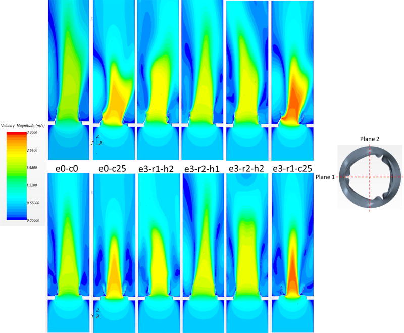
Figure 6.
Velocity contours in plane 1 (top) and plane 2 (bottom) for different valve deployments.
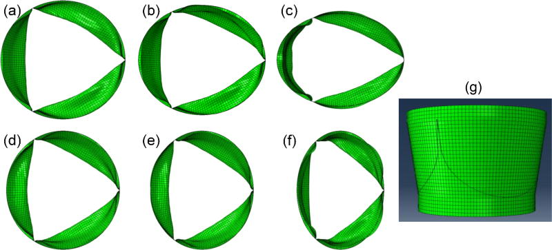
Since there are three leaflets in a TAV device, their relative positions to the major and minor axes of an elliptical TAV may have an impact on the deformed leaflet configuration. In this study, two orientations were investigated. For Scenario 1, the major axis was aligned with one of the three leaflet coaptation lines (Fig. 1a–c), which is denoted as “r1”. For Scenario 2, the major axis was perpendicular to the leaflet coaptation lines (Fig. 1d–f), which is denoted as “r2”. Since there is a possibility that only one section of TAV device along the axial direction is deployed into the elliptical shape, we have created TAV models with uniform ellipticity from the TAV annulus to the TAV commissures, and also with ellipticity at the TAV annulus only (i.e. with a circular shape at the TAV commissures). These two scenarios are designated as “h1” and “h2”, respectively. For example, a TAV model with a uniform eccentricity of 0.30 through the whole stent height, and with the major axis aligned with the coaptation lines is named “e1-r1-h1” (Fig. 1b). Thus, we have created twelve elliptical TAV models. The nominal circular TAV model is denoted as “e0-c0”.
Figure 1.
Selected TAV models used in the simulations. (a) e1-r1-h1, (b) e2-r1-h1, (c) e3-r1-h1, (d) e1-r2-h1, (e) e2-r2-h1, (f) e3-r2-h1, (g) e0-c25.
In addition, two cases of annular area constriction of 17%, denoted by “c17”, and 25%, or “c25”, with respect to the circular case were investigated (Fig. 1g). This scenario represents oversized valve used in TAV deployment. Two cases, “e0-c17” and “e0-c25”, were created such that the commissures of the valve were in a circular undistorted configuration. The two constricted annulus scenarios (with normal circularity at the commissures) were applied to the three ellipticity scenarios and two rotations to a total of additional 12 orientations. In total, 27 computational models were created.
Finite Element Model
Implementation of the Fung-elastic material model in ABAQUS (Dassault Systèmes SIMULIA Corp., RI) followed the methods previously established (Sun and Sacks, 2005). Each leaflet has its own material orientations, which are described by the constitutive law of Eq. (1). The stiffer material orientation of the pericardium tissue was aligned with the circumferential direction of the leaflets, the less stiff orientation was aligned with the radial direction. The contact between each pair of leaflets was modeled by using a master-slave contact pair with the contact surfaces defined on the ventricular side of the leaflets. Since the material of the stent is much stiffer than that of the leaflet, the deformation of the stent was neglected in this study. All the nodes on the leaflet-stent attachment contour lines were constrained in all three translational degrees of freedom. By applying a transvalvular pressure of 4 mmHg to the ventricular side of the leaflets, a quasi-static approach was used to analyze the deformation of the TAV from the unloaded to the fully opened state.
Computational Fluid Dynamics Model
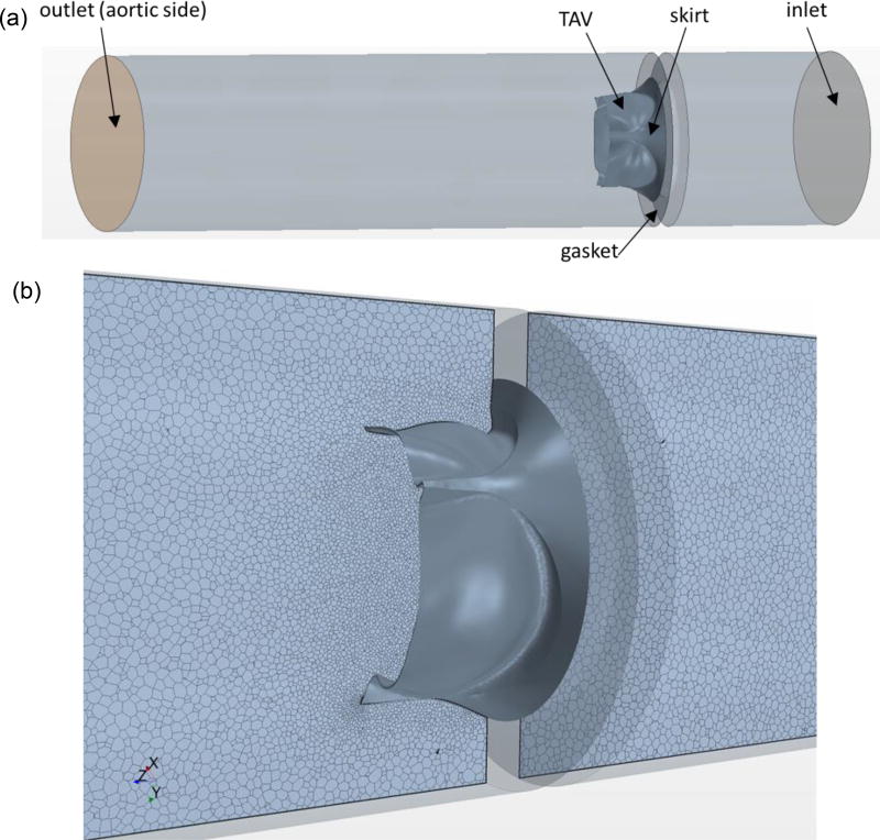
To quantify the hemodynamics of TAVs in the opened position, the CFD software Star-CCM+ (CD-Adapco, MI) was used. The guideline of ISO-5840 was followed for the steady forward flow testing of a prosthetic heart valve (appendix L.3 (1994)). Briefly, an incompressible fluid with a constant density of 1060 kg/m3 and a viscosity of 0.0035 Pa · s was modeled in a 36.8 mm length tube. The valve was mounted centrally and sealed to the wall using a gasket (Fig. 2a). The inlet and outlet boundaries were 1.5 valve diameters upstream and five diameters downstream from the valve to prevent any boundary effects at the valve region. A polyhedral volume mesh was generated, with denser meshes used along the leaflet surfaces and at the joining of stent and gasket. The model was fully three-dimensional, containing approximately 1.3–1.4 million cells per model (Fig. 2b). Mesh convergence was performed to ensure the model fidelity. Turbulence modeling was performed using the realizable k-epsilon model (Sirois and Sun, 2011). The turbulence intensity was set to 10% and the turbulent length scale was set to 3.5 mm. Following the ISO-5840 guidelines, a flow rate of 30 L/min was prescribed at the inlet and a constant pressure of 100 mmHg was applied at the outlet.
Figure 2.
(a) Three-dimensional CFD model for TAV simulations. (b) Polyhedral CFD mesh is shown in a bileaflet cross-sectional plane around TAV.
In vitro Experiment
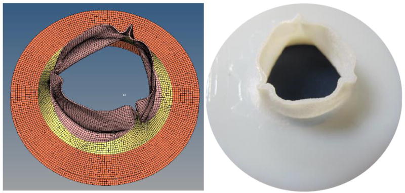
The TAV geometries used in the CFD studies were replicated using stereolithography (Fig. 3). The valves were mounted into a custom-built steady flow loop. A centrifugal pump was used to create the flow conditions used in the CFD analysis. The test fluid was normal saline (0.9% NaCl) at body temperature (37 °C). It has been reported that the viscosity of the fluid has a negligible effect on the transvalvular pressure drop and has been frequently used with pulse duplicators (Young et al., 2011). The flow loop was comprised of long cylindrical sections before and after the mounting area of the valve to prevent excessive turbulence. Flow straighteners were used approximately ten valve diameters upstream of the test section. A pressure transducer (World Precision Instruments, FL) was used to record the centerline pressure of the fluid at 2mm intervals starting one diameter upstream of the valve to three diameters downstream of the annulus.
Figure 3.
CAD model of a TAV in the open configuration (left) and the corresponding fabricated stereolithography model (right).
Definition of the Calculated Quantities
The following parameters were used to characterize hemodynamics through the valve: transvalvular pressure gradient (TPG) and turbulent viscous shear stress (TVSS). TPG was calculated as the pressure difference across the valve. TVSS has been correlated to blood cell damage in turbulent flow, which relates to turbulent dissipation rates which occur at Kolmogorov length scale (Jones, 1995). TVSS (Yen et al., 2014) can be calculated as , where µ is the dynamic viscosity of the fluid, ε is the turbulent dissipation rate (Morshed et al., 2014).
RESULTS
Experimental Validation
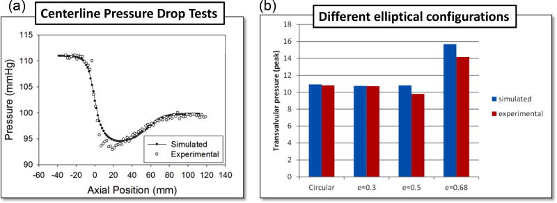
From Figure 4a it can be seen that the computational results and the experimental measurements of the valve centerline pressure follow similar trends. The region with the greatest discrepancy occurred immediately downstream of the valve. The simulated minimum centerline pressure for the circular TAV was 94 mmHg at 22mm downstream of the annulus. The experimental results showed a minimum pressure of 92.5 mmHg at 20mm downstream. Both the experimental and computational data showed consistent curves for the distance 24mm and further downstream of the annulus. Figure 4b shows TPG for four cases with different ellipticity. The simulation results matched with the experiments.
Figure 4.
(a) Centerline pressure drop comparison between simulation and experiment for the nominal circular case (e0-c0). (b) Comparison of simulated and experimental pressure drop for the cases: e0-c0, e1-r1-h1, e2-r1-h1, e3-r1-h1.
Flow characteristics from CFD Results
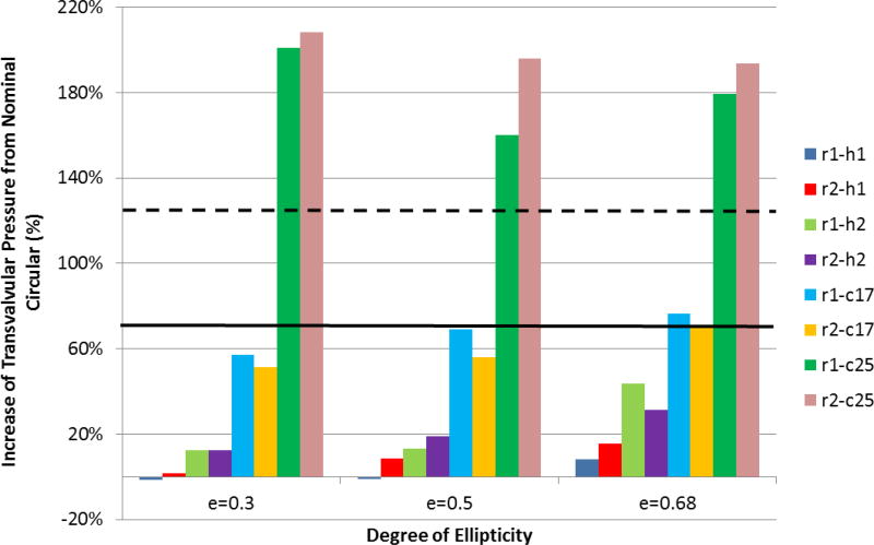
The impact of TAV configurations on the TPG is shown in Figure 5. TPG generally increases with the increasing of TAV ellipticity, except for the scenario with severe under-expanded TAVs (r1-c25 and r2-c25). The baseline circular valve was found to have a peak transvalvular pressure gradient (PTPG) of 10.92 mmHg, while the circular under-expanded valves of 17% and 25% (e0-c17 and e0-c25) had PTPGs of 18.54 mmHg and 24.50 mmHg, respectively. For valve deployment with mild (e=0.30) or moderate (e=0.50) ellipticity, PTPG was even smaller than that of the nominal circular valve (e.g., for cases of e1-r1-h1, e1-r2-h1, e2-r1-h1). Variation of ellipticity along the stent height (i.e., scenarios h1 and h2) had influences on valve performance as well. It was found that h2 scenarios had higher PTPGs than their h1 counterparts. TAV orientation had a minor effect on PTPG, where no optimal orientation for all situations was found. The change in PTPG was more pronounced under the annular constriction when compared to the change in ellipticity. The greatest increase of PTPG occurred at the largest annular constriction (25%) but with a mild ellipticity of e=0.30.
Figure 5.
The increase of transvalvular pressure gradient with respect to the nominal circular TAV for variations in ellipticity, orientation, annulus constriction and height uniformity. The solid and dashed lines represent the results of scenario e0-c17 and e0-c25, respectively.
Additionally, flow velocity contours were measured in a long-axis plane that passed through a valve commissure and bisected the other leaflet (plane 1), and a plane (plane 2) perpendicular to plane 1, as shown in Figure 6. The nominal circular valve (e0-c0) was found to have an almost symmetric center jet in plane 1 with a peak velocity of 2.16 m/s. The central jet in e0-c0 case propagated with the longest distance downstream, implying it had less energy dissipation loss, thus better hemodynamic performance. Based on the central jet length, hemodynamic performance of the remaining cases in descending order were e3-r2-h1, e3-r2-h2, e3-r1-h2, e0-c25, and e3-r1-c25. In general, the maximum velocity followed the same trend of PTPG, which the smallest velocity corresponding to the lowest PTPG. The central jets in plane 2 were more symmetric compared with the jets in plane 1 because the leaflet profiles were almost symmetric in plane 2. The large-scale features of the central jet were largely affected by the valve’s geometry.
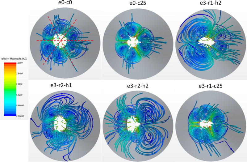
The vortices created by the central jet are represented using 3D streamlines in Figure 7. For the nominal case, there were six vortex rings distributed almost axisymmetrically downstream the valve. The same phenomena were observed for the under-expanded deployments (e.g., e0-c25, e3-r1-c25). However, the vortex rings were located closer to the centerline, creating smaller central jet orifices. In the cases of large ellipticity without under-expansion (e.g., e3-r1-h2), the vortex rings became irregular. The central flow was substantially confined, resulting in strong interaction between the vortex ring and the central jet downstream, as shown in Figure 6. It is conjectured that smaller and less spread vortex rings decrease energy dissipation, leading to better hemodynamic performance.
Figure 7.
3D streamline patterns in top view for different valve deployments. The streamlines are colored by velocity magnitude.
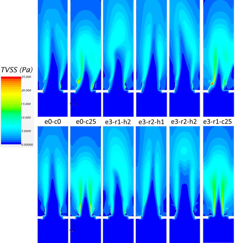
The TVSS distribution, defined previously, is shown in Figure 8. Generally, regions with high TVSS were observed in the shear layer region between the central jet and the edge of the leaflets, and also along the wake of the leaflets. Regions of high TVSS were expanded with increasing central jet velocity. Therefore, the cases of under-expansion had a larger area with elevated TVSS. The maximum values of TVSS in Figure 8 were 13 Pa, 22 Pa, 16 Pa, 11 Pa, 11 Pa, 25 Pa, from the left to the right, respectively. Comparing elliptical without under-expansion cases to the nominal one, TVSS distributions were not significantly changed.
Figure 8.
Turbulent viscous shear stress contours in plane 1 (top) and plane 2 (bottom) for different valve deployments.
DISCUSSION
Although the TAV is designed for circular deployment, the TAV device landing zone often has a non-circular shape (Zegdi et al., 2008). The balloon-expandable Edwards SAPIEN valve often has a mild elliptical shape after deployment, whereas the self-expandable CoreValve stent is soft, and thus may exhibit a stronger elliptical shape (Schuhbaeck et al., 2015). The oversizing of TAVs has been commonly used clinically as a compromise to prevent the risk of the paravalvular leak. Therefore, the elliptical and under-expanded TAV deployment scenarios considered in this study provide a detailed investigation of different post-deployment configurations based on clinical evidence (Gooley et al., 2015; Schultz et al., 2009). It has been found that the ellipticity after deployment at different height levels of the TAV may not be the same (Kazuno et al., 2016; Rodríguez-Olivares et al., 2016). Thus, the deployment scenarios of h1 and h2 approximately represent this observation.
To our best knowledge, this study is the first to systematically analyze the impact of abnormal TAV deployment on the valve hemodynamics using an integrated computational and experimental approach. Although the effect of ellipticity and under-expanded deployment of TAVs on valvular hemodynamics has been studied previously by in vitro experiments (Feng et al., 2017; Gunning et al., 2014; Kuetting et al., 2014; Salaun et al., 2016; Scharfschwerdt et al., 2014; Young et al., 2011), some of these studies have shown contradictory results due to the lack of parametric control. A study (Gunning et al., 2014) found that the circular valve had a lower mean TPG compared with the elliptical valve for the test condition of 5 L/min CO (6.9 vs. 8.0 mmHg). The eccentric valve used in this study is close to our e3-r2-h1 scenario. The increase of TPG is 16% compared with the circular case, which agrees well with an increase of 15% from our simulations. In another study, 26 mm non-commercial nitinol TAVs were deployed with four different configurations: circular, elliptical, triangular, and constricted circular geometries (Young et al., 2011). Each configuration was tested in a half configuration, in which only the inflow portion of the valve was constrained (corresponding to “h2” scenarios), and in a full configuration (corresponding to “h1” scenarios). It was found that the circular valve had a higher TPG than elliptical configurations. Since the eccentricity of the value was not given, it is conjectured that the valve was deployed into a slightly elliptical annulus. Therefore, smaller TPG in elliptical configurations can be explained by the results of our simulations for scenarios e1-r1-h1 and e2-r1-h1. Young et al. (Young et al., 2011) also observed no significant difference between the half and full configurations in terms of TPG, whereas our simulations showed that “h1” configuration had a smaller PTPG than that of “h2” configuration. This may be explained by two reasons: 1) the stent shape at the commissure level in their half-configurations may not maintain a perfect circular shape as assumed in our h1 scenarios; and 2) under slightly elliptical conditions, the difference in PTPG is small between the full and half-configurations, which is around 10% difference in our simulations (e.g., e1-r1-h1 vs. e1-r1-h2). In their experiment, the highly constricted circular configuration had a much large increase (more than 150%) in TPG compared to the nominal case, which agrees with our results (e0-c0 vs. e0-c25).
Kuetting et al. (Kuetting et al., 2014) investigated the influence of aortic annulus ovality on the hydrodynamics of the Medtronic CoreValve prostheses through in vitro experiment. They found that TVG increased with rising ellipticity and that more significant ovality lead to worsening of valve function and regurgitation. These findings are consistent with our results. The Edwards SAPIEN XT valve was also investigated in noncircular aortic annuli (Scharfschwerdt et al., 2014). It was reported that mean and peak TPGs were not influenced by the annulus configurations. By examining the annulus shape, it was found that the 24 mm artificial annuli used could cause a constriction of 15%. Therefore, their results can be compared to the scenarios of “c17” in our simulations. From our results, the e0-c17 case had a PTPG similar to the elliptical scenarios with the same degree of annular constriction. Again, our results agree with the experimental observations. Salaun et al. (Salaun et al., 2016) investigated the effect of oversizing and elliptical shape on Edwards SAPIEN valves. They found that for a given aortic annulus area, mean TPGs were generally lower with elliptical annuli compared to circular annuli. Interestingly, this observation can be partially explained by our results that under moderate under-expansion (“c17” scenarios), ellipticity may achieve a slightly better hydrodynamic performance compared with the circular case. This phenomenon is probably dependent on TAV leaflet design. In summary, the findings of this computational study are in accordance with several in vitro studies. The discrepancies in the experiments are mostly derived from the different degrees of under-expansion and ellipticity. However, based on the parametric study from well-controlled numerical simulations, these discrepancies can be explained.
In addition to the bulk hemodynamic criteria such as TPG, the detailed flow pattern and TVSS distribution were also examined. It is known that elevated levels of shear stresses may lead to hemolysis and thrombosis (Sutera, 1977). Previously, hemolysis was thought to be caused by Reynolds shear stress (RSS) in turbulent flows (Grigioni et al., 1999). A more recent hypothesis suggests that TVSS at spatial scales similar to red blood cells are related to their damage (Antiga and Steinman, 2009; Ge et al., 2008). The threshold TVSS value for hemolysis in turbulent flows was found to be 60 Pa with a short exposure time of 0.012 ms (Yen et al., 2014), while the corresponding RSS threshold was 340 Pa. For the circular case, the maximum TVSS from our simulation is about 13 Pa, which is similar to a value of 12 Pa from an in vitro experiment (Li et al., 2010). In all simulations, the TVSS values were smaller than 30 Pa, thus may not be sufficient to induce blood cell damage. Unlike red blood cells, platelets are more sensitive to shear stresses. It was reported the levels of TVSS in the range from 10 to 100 Pa can lead to platelets activation (Sutera, 1977). Our results indicated that platelets activation may occur through the TAV during peak systole. However, if we consider the short exposure time due to the high velocity through the valve, the effect on platelets activation is yet to be confirmed.
Currently, there is substantial effort to expand TAVR to lower risk patients (Gravel and Généreux, 2015) after positive clinical results in intermediate risk patients. However, recent evidence of leaflet thrombosis in TAVs (De Marchena et al., 2015; Makkar et al., 2015) has led to concerns of stroke and long-term valve durability. Although risk factors for thrombosis in TAVR patients remain poorly defined, recent data suggest that the hemodynamic environment in the vicinity of the TAV is a factor in the development of leaflet thrombosis (Egbe et al., 2015; Hansson et al., 2016; Leetmaa et al., 2015). This environment can be altered by anatomical, procedural and device related parameters, such as the elliptical deployment of TAV studied in this paper. In the future, we hope that the developed computational models can be combined with the established TAV fatigue model in our lab (Martin and Sun, 2014, 2015) to investigate the altered hemodynamics on leaflet thrombosis and TAV durability due to the suboptimal TAV developments.
There are some limitations in this study. Only one initial leaflet geometry was used to create the abnormal TAV models. Alternative initial leaflet geometries may generate different results (Li and Sun, 2017; Thubrikar et al., 1991). However, it is expected that the overall trends in pressure gradient and flow patterns will hold for different TAV designs. Another limitation was the use of a fully opened leaflet configuration in the steady forward flow. Therefore, transvalvular regurgitation during diastole cannot be studied. During a cardiac cycle, the valve leaflets interact with the fluid stream which could cause the leaflets to deform and affect the flow. Thus, the unsteady changes in flow may not be captured. More accurate flow simulations may be achieved with valve fluid-structure interactions (Mao et al., 2016) rather than retaining a fixed leaflet wall boundary.
In conclusion, we systematically investigated the effect of elliptical and under-expansion deployments on TAV hemodynamics. The results of numerical simulations were compared to the in vitro experiment to verify the accuracy of numerical method. Our findings show that slight ellipticity of TAVs may not necessarily lead to degeneration of hydrodynamic performance. However, under large ellipticity, increases in TPG were observed. Under-expansion has a much greater negative effect on TAV hemodynamics than valve ellipticity. The maximum TVSS values were found to be significantly larger in under-expanded TAVs, but these values were not large enough to cause hemolysis in all cases.
References
- International Standards Organization. ISO5840: Cardiovascular implants—Cardiac valve prosthesis (Committee draft) International Standards Organization; Geneva, Switzerland: 1994. pp. 18–24. [Google Scholar]
- Antiga L, Steinman DA. Rethinking turbulence in blood. Biorheology. 2009;46:77–81. doi: 10.3233/BIR-2009-0538. [DOI] [PubMed] [Google Scholar]
- Blanke P, Schoepf UJ, Leipsic JA. CT in transcatheter aortic valve replacement. Radiology. 2013;269:650–669. doi: 10.1148/radiol.13120696. [DOI] [PubMed] [Google Scholar]
- Cribier A. The development of transcatheter aortic valve replacement (TAVR) Global Cardiology Science and Practice. 2017;2016 doi: 10.21542/gcsp.2016.32. [DOI] [PMC free article] [PubMed] [Google Scholar]
- Cribier A, Eltchaninoff H, Bash A, Borenstein N, Tron C, Bauer F, Derumeaux G, Anselme F, Laborde F, Leon MB. Percutaneous transcatheter implantation of an aortic valve prosthesis for calcific aortic stenosis: first human case description. Circulation. 2002;106:3006–3008. doi: 10.1161/01.cir.0000047200.36165.b8. [DOI] [PubMed] [Google Scholar]
- De Marchena E, Mesa J, Pomenti S, y Kall CM, Marincic X, Yahagi K, Ladich E, Kutys R, Aga Y, Ragosta M. Thrombus formation following transcatheter aortic valve replacement. JACC: Cardiovascular Interventions. 2015;8:728–739. doi: 10.1016/j.jcin.2015.03.005. [DOI] [PubMed] [Google Scholar]
- Delgado V, Ng AC, van de Veire NR, van der Kley F, Schuijf JD, Tops LF, de Weger A, Tavilla G, de Roos A, Kroft LJ, Schalij MJ, Bax JJ. Transcatheter aortic valve implantation: role of multi-detector row computed tomography to evaluate prosthesis positioning and deployment in relation to valve function. Eur Heart J. 2010;31:1114–1123. doi: 10.1093/eurheartj/ehq018. [DOI] [PubMed] [Google Scholar]
- Egbe AC, Pislaru SV, Pellikka PA, Poterucha JT, Schaff HV, Maleszewski JJ, Connolly HM. Bioprosthetic valve thrombosis versus structural failure: clinical and echocardiographic predictors. Journal of the American College of Cardiology. 2015;66:2285–2294. doi: 10.1016/j.jacc.2015.09.022. [DOI] [PubMed] [Google Scholar]
- Feng W, Yang X, Liu Y, Fan Y. An In Vitro Feasibility Study of the Influence of Configurations and Leaflet Thickness on the Hydrodynamics of Deformed Transcatheter Aortic Valve. Artificial Organs. 2017 doi: 10.1111/aor.12833. [DOI] [PubMed] [Google Scholar]
- Fung YC. Biomechanics: Mechanical Properties of Living Tissues. 2. Springer Verlag; New York: 1993. [Google Scholar]
- Ge L, Dasi LP, Sotiropoulos F, Yoganathan AP. Characterization of hemodynamic forces induced by mechanical heart valves: Reynolds vs. viscous stresses. Annals of Biomedical Engineering. 2008;36:276–297. doi: 10.1007/s10439-007-9411-x. [DOI] [PubMed] [Google Scholar]
- Gooley RP, Cameron JD, Meredith IT. Assessment of the geometric interaction between the lotus transcatheter aortic valve prosthesis and the native ventricular aortic interface by 320-multidetector computed tomography. JACC Cardiovasc Interv. 2015;8:740–749. doi: 10.1016/j.jcin.2015.03.002. [DOI] [PubMed] [Google Scholar]
- Gravel GM, Généreux P. Exploring the Role of Transcatheter Aortic Valve Replacement as the Preferred Treatment for Lower-Risk Patients. Journal of the American College of Cardiology. 2015;66:1638. doi: 10.1016/j.jacc.2015.06.1346. [DOI] [PubMed] [Google Scholar]
- Grigioni M, Daniele C, D'Avenio G, Barbaro V. A discussion on the threshold limit for hemolysis related to Reynolds shear stress. Journal of biomechanics. 1999;32:1107–1112. doi: 10.1016/s0021-9290(99)00063-9. [DOI] [PubMed] [Google Scholar]
- Gunning PS, Saikrishnan N, McNamara LM, Yoganathan AP. An in vitro evaluation of the impact of eccentric deployment on transcatheter aortic valve hemodynamics. Ann Biomed Eng. 2014;42:1195–1206. doi: 10.1007/s10439-014-1008-6. [DOI] [PubMed] [Google Scholar]
- Hansson NC, Grove EL, Andersen HR, Leipsic J, Mathiassen ON, Jensen JM, Jensen KT, Blanke P, Leetmaa T, Tang M. Transcatheter aortic valve thrombosis: incidence, predisposing factors, and clinical implications. Journal of the American College of Cardiology. 2016;68:2059–2069. doi: 10.1016/j.jacc.2016.08.010. [DOI] [PubMed] [Google Scholar]
- Himbert D, Pontnau F, Messika-Zeitoun D, Descoutures F, Detaint D, Cueff C, Sordi M, Laissy JP, Alkhoder S, Brochet E, Iung B, Depoix JP, Nataf P, Vahanian A. Feasibility and outcomes of transcatheter aortic valve implantation in high-risk patients with stenotic bicuspid aortic valves. Am J Cardiol. 2012;110:877–883. doi: 10.1016/j.amjcard.2012.04.064. [DOI] [PubMed] [Google Scholar]
- Jones SA. A relationship between Reynolds stresses and viscous dissipation: implications to red cell damage. Annals of biomedical engineering. 1995;23:21–28. doi: 10.1007/BF02368297. [DOI] [PubMed] [Google Scholar]
- Kazuno Y, Maeno Y, Kawamori H, Takahashi N, Abramowitz Y, Babak H, Kashif M, Chakravarty T, Nakamura M, Cheng W. Comparison of SAPIEN 3 and SAPIEN XT transcatheter heart valve stent-frame expansion: evaluation using multi-slice computed tomography. European heart journal cardiovascular Imaging, jew032. 2016 doi: 10.1093/ehjci/jew032. [DOI] [PMC free article] [PubMed] [Google Scholar]
- Kuetting M, Sedaghat A, Utzenrath M, Sinning J-M, Schmitz C, Roggenkamp J, Werner N, Schmitz-Rode T, Steinseifer U. In vitro assessment of the influence of aortic annulus ovality on the hydrodynamic performance of self-expanding transcatheter heart valve prostheses. Journal of biomechanics. 2014;47:957–965. doi: 10.1016/j.jbiomech.2014.01.024. [DOI] [PubMed] [Google Scholar]
- Leetmaa T, Hansson NC, Leipsic J, Jensen K, Poulsen SH, Andersen HR, Jensen JM, Webb J, Blanke P, Tang M. Early Aortic Transcatheter Heart Valve Thrombosis. Circulation: Cardiovascular Interventions. 2015;8:e001596. doi: 10.1161/CIRCINTERVENTIONS.114.001596. [DOI] [PubMed] [Google Scholar]
- Leon MB, Smith CR, Mack M, Miller DC, Moses JW, Svensson LG, Tuzcu EM, Webb JG, Fontana GP, Makkar RR, Brown DL, Block PC, Guyton RA, Pichard AD, Bavaria JE, Herrmann HC, Douglas PS, Petersen JL, Akin JJ, Anderson WN, Wang D, Pocock S Investigators, P.T. Transcatheter aortic-valve implantation for aortic stenosis in patients who cannot undergo surgery. N Engl J Med. 2010;363:1597–1607. doi: 10.1056/NEJMoa1008232. [DOI] [PubMed] [Google Scholar]
- Li C-P, Lo C-W, Lu P-C. Estimation of viscous dissipative stresses induced by a mechanical heart valve using PIV data. Annals of biomedical engineering. 2010;38:903–916. doi: 10.1007/s10439-009-9867-y. [DOI] [PubMed] [Google Scholar]
- Li K, Sun W. Simulated thin pericardial bioprosthetic valve leaflet deformation under static pressure-only loading conditions: implications for percutaneous valves. Ann Biomed Eng. 2010;38:2690–2701. doi: 10.1007/s10439-010-0009-3. [DOI] [PubMed] [Google Scholar]
- Li K, Sun W. Simulated transcatheter aortic valve deformation: A parametric study on the impact of leaflet geometry on valve peak stress. Int J Numer Method Biomed Eng. 2017;33 doi: 10.1002/cnm.2814. [DOI] [PMC free article] [PubMed] [Google Scholar]
- Makkar RR, Fontana G, Jilaihawi H, Chakravarty T, Kofoed KF, De Backer O, Asch FM, Ruiz CE, Olsen NT, Trento A. Possible subclinical leaflet thrombosis in bioprosthetic aortic valves. New England Journal of Medicine. 2015;373:2015–2024. doi: 10.1056/NEJMoa1509233. [DOI] [PubMed] [Google Scholar]
- Mao WB, Li KW, Sun W. Fluid-Structure Interaction Study of Transcatheter Aortic Valve Dynamics Using Smoothed Particle Hydrodynamics. Cardiovascular Engineering and Technology. 2016;7:374–388. doi: 10.1007/s13239-016-0285-7. [DOI] [PMC free article] [PubMed] [Google Scholar]
- Martin C, Sun W. Simulation of long-term fatigue damage in bioprosthetic heart valves: effects of leaflet and stent elastic properties. Biomechanics and modeling in mechanobiology. 2014;13:759–770. doi: 10.1007/s10237-013-0532-x. [DOI] [PMC free article] [PubMed] [Google Scholar]
- Martin C, Sun W. Comparison of transcatheter aortic valve and surgical bioprosthetic valve durability: A fatigue simulation study. Journal of biomechanics. 2015;48:3026–3034. doi: 10.1016/j.jbiomech.2015.07.031. [DOI] [PMC free article] [PubMed] [Google Scholar]
- Morshed KN, Bark D, Jr, Forleo M, Dasi LP. Theory to predict shear stress on cells in turbulent blood flow. PloS one. 2014;9:e105357. doi: 10.1371/journal.pone.0105357. [DOI] [PMC free article] [PubMed] [Google Scholar]
- Rodríguez-Olivares R, Rahhab Z, El Faquir N, Ren B, Geleijnse M, Bruining N, van Mieghem NM, Schultz C, Lauritsch G, de Jaegere PP. Differences in frame geometry between balloon-expandable and self-expanding transcatheter heart valves and association with aortic regurgitation. Revista Española de Cardiología (English Edition) 2016;69:392–400. doi: 10.1016/j.rec.2015.08.010. [DOI] [PubMed] [Google Scholar]
- Salaun E, Zenses A-S, Evin M, Collart F, Habib G, Pibarot P, Rieu R. Effect of oversizing and elliptical shape of aortic annulus on transcatheter valve hemodynamics: An in vitro study. International journal of cardiology. 2016;208:28–35. doi: 10.1016/j.ijcard.2016.01.048. [DOI] [PubMed] [Google Scholar]
- Scharfschwerdt M, Meyer-Saraei R, Schmidtke C, Sievers HH. Hemodynamics of the Edwards Sapien XT transcatheter heart valve in noncircular aortic annuli. J Thorac Cardiovasc Surg. 2014;148:126–132. doi: 10.1016/j.jtcvs.2013.07.057. [DOI] [PubMed] [Google Scholar]
- Schuhbaeck A, Weingartner C, Arnold M, Schmid J, Pflederer T, Marwan M, Rixe J, Nef H, Schneider C, Lell M, Uder M, Ensminger S, Feyrer R, Weyand M, Achenbach S. Aortic annulus eccentricity before and after transcatheter aortic valve implantation: Comparison of balloon-expandable and self-expanding prostheses. Eur J Radiol. 2015;84:1242–1248. doi: 10.1016/j.ejrad.2015.04.003. [DOI] [PubMed] [Google Scholar]
- Schultz CJ, Weustink A, Piazza N, Otten A, Mollet N, Krestin G, van Geuns RJ, de Feyter P, Serruys PWJ, de Jaegere P. Geometry and Degree of Apposition of the CoreValve ReValving System With Multislice Computed Tomography After Implantation in Patients With Aortic Stenosis. Journal of the American College of Cardiology. 2009;54:911–918. doi: 10.1016/j.jacc.2009.04.075. [DOI] [PubMed] [Google Scholar]
- Sirois E, Sun W. Computational evaluation of platelet activation induced by a bioprosthetic heart valve. Artificial organs. 2011;35:157–165. doi: 10.1111/j.1525-1594.2010.01048.x. [DOI] [PubMed] [Google Scholar]
- Smith CR, Leon MB, Mack MJ, Miller DC, Moses JW, Svensson LG, Tuzcu EM, Webb JG, Fontana GP, Makkar RR, Williams M, Dewey T, Kapadia S, Babaliaros V, Thourani VH, Corso P, Pichard AD, Bavaria JE, Herrmann HC, Akin JJ, Anderson WN, Wang D, Pocock SJ. Transcatheter versus surgical aortic-valve replacement in high-risk patients. N Engl J Med. 2011;364:2187–2198. doi: 10.1056/NEJMoa1103510. [DOI] [PubMed] [Google Scholar]
- Sun W, Li K, Sirois E. Simulated elliptical bioprosthetic valve deformation: implications for asymmetric transcatheter valve deployment. J Biomech. 2010;43:3085–3090. doi: 10.1016/j.jbiomech.2010.08.010. [DOI] [PubMed] [Google Scholar]
- Sun W, Sacks MS. Finite element implementation of a generalized Fung-elastic constitutive model for planar tissues. Biomechanics and Modeling in Mechanobiology. 2005;4:190–199. doi: 10.1007/s10237-005-0075-x. [DOI] [PubMed] [Google Scholar]
- Sutera SP. Flow-induced trauma to blood cells. Circulation research. 1977;41:2–8. doi: 10.1161/01.res.41.1.2. [DOI] [PubMed] [Google Scholar]
- Thubrikar MJ, Samanta S, Nolan SP. Optimization of a trileaflet valve design. Journal of long-term effects of medical implants. 1991;1:171–192. [PubMed] [Google Scholar]
- Webb JG, Chandavimol M, Thompson CR, Ricci DR, Carere RG, Munt BI, Buller CE, Pasupati S, Lichtenstein S. Percutaneous aortic valve implantation retrograde from the femoral artery. Circulation. 2006;113:842–850. doi: 10.1161/CIRCULATIONAHA.105.582882. [DOI] [PubMed] [Google Scholar]
- Willson AB, Webb JG, Labounty TM, Achenbach S, Moss R, Wheeler M, Thompson C, Min JK, Gurvitch R, Norgaard BL, Hague CJ, Toggweiler S, Binder R, Freeman M, Poulter R, Poulsen S, Wood DA, Leipsic J. 3-dimensional aortic annular assessment by multidetector computed tomography predicts moderate or severe paravalvular regurgitation after transcatheter aortic valve replacement: a multicenter retrospective analysis. J Am Coll Cardiol. 2012;59:1287–1294. doi: 10.1016/j.jacc.2011.12.015. [DOI] [PubMed] [Google Scholar]
- Yen J-H, Chen S-F, Chern M-K, Lu P-C. The effect of turbulent viscous shear stress on red blood cell hemolysis. Journal of Artificial Organs. 2014;17:178–185. doi: 10.1007/s10047-014-0755-3. [DOI] [PubMed] [Google Scholar]
- Young E, Chen JF, Dong O, Gao S, Massiello A, Fukamachi K. Transcatheter heart valve with variable geometric configuration: in vitro evaluation. Artif Organs. 2011;35:1151–1159. doi: 10.1111/j.1525-1594.2011.01331.x. [DOI] [PubMed] [Google Scholar]
- Zajarias A, Cribier AG. Outcomes and Safety of Percutaneous Aortic Valve Replacement. Journal of the American College of Cardiology. 2009;53:1829–1836. doi: 10.1016/j.jacc.2008.11.059. [DOI] [PubMed] [Google Scholar]
- Zegdi R, Ciobotaru V, Noghin M, Sleilaty G, Lafont A, Latrémouille C, Deloche A, Fabiani J-N. Is It Reasonable to Treat All Calcified Stenotic Aortic Valves With a Valved Stent?: Results From a Human Anatomic Study in Adults. Journal of the American College of Cardiology. 2008;51:579–584. doi: 10.1016/j.jacc.2007.10.023. [DOI] [PubMed] [Google Scholar]
- Zhao Z-G, Jilaihawi H, Feng Y, Chen M. Transcatheter aortic valve implantation in bicuspid anatomy. Nat Rev Cardiol. 2015;12:123–128. doi: 10.1038/nrcardio.2014.161. [DOI] [PubMed] [Google Scholar]


