Abstract
We propose and theoretically investigate a dispersion-engineered Si3N4 microring resonator, based on a cross-section containing a partially-etched trench, that supports phase-locked, two-color soliton microcomb states. These soliton states consist of a single circulating intracavity pulse with a modulated envelope that sits on a continuous wave background. Such temporal waveforms produce a frequency comb whose spectrum is spread over two widely-spaced spectral windows, each exhibiting a squared hyperbolic secant envelope, with the two windows phase-locked to each other via Cherenkov radiation. The first spectral window is centered around the 1550 nm pump, while the second spectral window is tailored based on straightforward geometric control, and can be centered as short as 750 nm and as long as 3000 nm. We numerically analyze the robustness of the design to parameter variation, and consider its implications to self-referencing and visible wavelength comb generation.
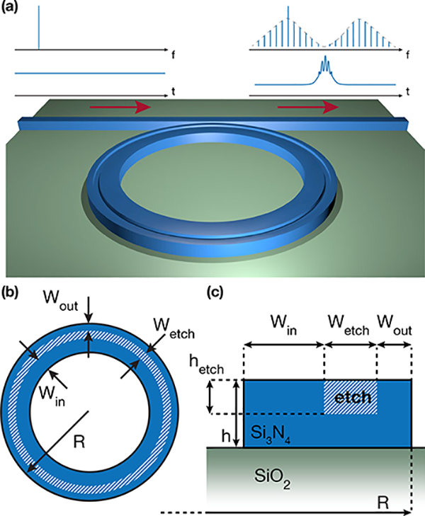
Optical frequency synthesis [1], low-noise microwave generation [2], and optical atomic clocks [3] often rely on a fully-stabilized optical frequency comb as a core component [4]. Stabilization of the comb’s carrier-envelope offset frequency is typically achieved via nonlinear interferometry, such as f-2 f self-referencing [5–7]. Optical frequency combs based on Kerr nonlinear microresonators [8] have recently emerged as a compelling approach to realizing compact, low-power operation, with octave-spanning soliton microcombs [9,10] having recently been self-referenced [11, 12]. Despite these recent advances, direct self-referencing of Kerr microcombs is quite challenging, with experimental demonstrations to date having required helper/transfer lasers, phase locked to a nearby comb tooth, to achieve detectable offset frequency beat notes [11–13]. The use of such lasers comes at the expense of additional system complexity, component cost, and operating power. A fundamental challenge in self-referencing a Kerr microcomb is that solitons have thus far been the only states to experimentally exhibit both the requisite broad spectral bandwidth and phase coherence across the comb, but the soliton’s characteristic squared hyperbolic secant spectral envelope limits the power in the comb lines relevant for self-referencing. Soliton-induced dispersive wave emission [11,14] has been identified as a means to dramatically enhance the power available in the relevant comb teeth, but the ideal scenario of achieving precise control of two dispersive waves (preferably at f and 2f) is a significant challenge [15], in particular due to their narrow spectral width and the sensitivity of the phase-matching conditions to geometric parameters [16]. In addition, developing soliton microcombs to cover other spectral windows, for example, to connect to visible wavelength atomic systems for clocks or to longer wavelengths for spectroscopy, often requires a wavelength change in the pump laser source. To overcome such challenges, the generation of multicolor single soliton states as proposed in Ref. [17] is of great interest. These states (Fig. 1(a)) produce a spectrum that is broken up into multiple windows, each of which exhibits a sech2 envelope. Temporally, they still consist of a single pulse circulating through the cavity, sitting on a continuous wave background, but their envelope exhibits modulations consistent with the multiple central frequencies. An open question is the degree to which realizable devices can exhibit the necessary dispersion profile to support such states, and the extent to which the dispersion can be optimized for specific applications.
Fig. 1.

Si3N4 microring design parameters on SiO2 substrate with air top cladding. (a) Schematic of the trench-ring geometry, producing from a continuous wave (CW) input a two-color single soliton state. The spectrum and temporal waveform associated with the input and output are indicated above the schematic. (b) Top view, and (c) cross section view. Blue corresponds to Si3N4, the hatched part to the etched trench.
Here, we present the theoretical analysis of a fabrication-friendly design for the generation of two-color soliton states, based on a straightforward modification to Si3N4 resonators that have successfully exhibited octave-spanning (single color) soliton states [9]. Each soliton color is supported by a local region of anomalous group velocity dispersion (GVD), and phase-matching of the two regions phase locks the two soliton colors to each other. Simple geometrical changes keep one soliton color centered at 200 THz (1550 nm) while the position of the second color is widely varied from 100 THz (3000 nm) to 400 THz (775 nm), with comb teeth at wavelengths as short as 680 nm. As we describe below, this is an appealing approach for the realization of self-referenced microresonator frequency combs that can address multiple relevant spectral regions, all while being pumped by a telecommunications-band laser.
To support a two-color soliton state as schematically depicted in Fig. 1(a), a Kerr microresonator must support a GVD profile that contains two anomalous GVD regions (and hence four zero-dispersion crossing points), each of which sustains a color of the soliton, and the two anomalous GVD windows must be phase-matched to allow energy exchange between the two soliton colors. As the basic rectangular (or trapezoidal) cross-section used in broad soliton microcombs to date only results in one anomalous GVD window, a more complex geometry must be introduced. A number of groups have considered such complex dispersion engineering, with most approaches relying on a layered cross section consisting of materials such as Si3N4, SiO2, and SiC [18–21]. However, such an approach introduces additional challenges in fabrication, in requiring the deposition, and in some cases, etching, of additional materials with fine control of dimension. In particular, we have found that the thickness control required to generate an appropriate dispersion profile for two-color solitons in the Si3N4 /SiCb platform is quite strict. Our proposed geometry, depicted in Fig. 1, instead relies on the straightforward etching of a trench within an air top clad, SiO2 bottom clad, Si3N4 microring resonator (radius R = 50 μm and thickness of h = 700 nm). Nominal dimensions for the trench are width Wefch, = 750 nm, depth hefch;, = 275 nm, and position from the outer (inner) part of the ring of Wout = 475 nm (Win = 1.575 μm).
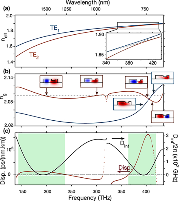
The trench is the key enabling feature for the requisite dispersion engineering, in enabling control of the spectral position and strength of an avoided mode crossing between the two first sets of transverse electric (TE) modes, namely TE1 and TE2. The effective index, group index, and dispersion of the these two modes are computed (Fig. 2(a)-(c)) using a finite element method eigensolver that includes material dispersion models for Si2N4 and SiO2. Both modes exhibit a first anomalous dispersion region around 200 THz, due to the compensation of the material dispersion by the ring dispersion (combination of waveguiding and bending effects). An avoided mode crossing around 400 THz (Fig. 2(a)) leads to a second anomalous dispersion region for the TE2 mode around this frequency (Fig. 2(b)-(c)). This anomalous GVD generation is similar to that recently reported between symmetric and anti-symmetric modes in concentric coupled resonators [22, 23], where the two optical paths cross and the mode is flipped (Fig. 2(b). However, here thanks to the two anomalous GVD windows, one can match both the group velocity and the phase between these regions (Fig. 2(b)-(c)). Indeed, the integrated dispersion, defined by Dint = wμ — (w0 + D1μ), where μ is an integer representing the relative mode number from the pumped one, w0 is the he angular frequency of the pumped mode, wμ the angular frequency of the μth mode, and D1 the free spectral range of the resonator, is zero for both the pumped mode and the central frequency of the anomalous dispersion region created by the avoided mode crossing. This allows energy transfer through Cherenkov radiation [24] between the two regions of the TE2 mode. Hence, by pumping one anomalous dispersion region and creating a first soliton color, power is transferred to the other anomalous dispersion region, ultimately leading to the formation of a second soliton color [17].
Fig. 2.

(a) Effective index versus frequency of the fundamental TE mode (TE1, blue) and second TE mode (TE2, red). The inset corresponds to the frequency position of the avoided mode-crossing. (b) Group index of the TE1 and TE2 modes (blue and red, respectively). Their radial electric field components are displayed at selected frequencies as insets. (c) Dispersion (red, left scale) and integrated dispersion (black, right scale) for the TE2 mode. The green areas highlight the two anomalous dispersion regions for TE2.
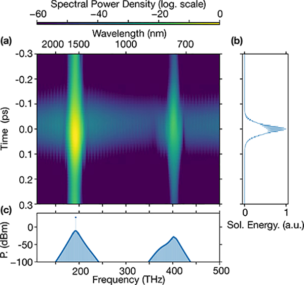
To investigate frequency comb generation in the soliton regime of this two matched anomalous GVD design, the Lugiato-Lefever equation [25], taking into account the dispersion of the TE2 mode previously computed, is solved in the temporal domain and results in the bound two-color soliton frequency comb represented in Fig. 3(a)-(c). Here we use a coupling and intrinsic quality factor Qc = Qi = 6 × 10⁶ and a pump located in the C-band with a power of |Ein|2 = 600 mW. The obtained spectrum exhibits two characteristic sech2 envelopes at the positions of the two anomalous dispersion regions, namely 200 THz and 400 THz (Fig. 3(c)). An important aspect to point out is that the two colors of the comb are part of a single soliton pulse, and are thus temporally bound and phase-locked, as represented in the spectrogram in Fig. 3(a). The result is a temporal single soliton pulse with a modulated envelope (Fig. 3(b)) due to the beating between the two spectral comb regions |S(t)|2 ∝ P1sech2 (t/Δτ1) + P2sech2 (t/Δτ2) + (t/Δτ1) sech (t/Δτ2) cos ((ω1 − ω2)t), where ω{1,2} are the central frequencies of the two frequency combs, and Δτ{1,2} are the temporal widths of the uncoupled solitons generated by each anomalous dispersion region with peak power P{1,2}.
Fig. 3.

(a) Spectrogram of the two-color soliton (log-scale color map). (b) Temporal profile of the multicolor soliton. (c) Output spectrum of the two-color soliton; 0 dB is referenced to 1 mW (i.e., dBm).
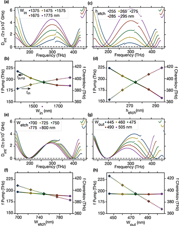
While it is important to point out the fabrication simplicity of our design, we need to ensure that the two-color soliton behavior is reasonably robust with respect to expected fabrication tolerances. Hence, simulations are performed where all the parameters from Fig. 1 are tuned independently, from which we extract the integrated dispersion and the position of both the pumped and the Cherenkov frequencies where the phase matching condition is respected, which in first order approximation corresponds to where Dint = 0. The least sensitive parameter is the inner width (Fig. 4(a)-(b)), which is consistent with the fact that it corresponds to the biggest component of the trenched microring, while the most sensitive parameter is the etch depth (Fig. 4(c)-(d)) as a variation of a few percent of the dimension could lead to a change in the central positions of both anomalous GVD windows. However, even with a variation of ±20 nm from the nominal etch depth (i.e., consistent with the expected fabrication uncertainty), the ability to achieve two phase-locked anomalous GVD regions remains. Interestingly, the width of the etched trench (Fig. 4(e)-(f)), has only a limited influence on the spectral positions of the two anomalous GVD regions. As pointed out in ref. [23], this dimension tunes the coupling between TE1 and TE2. Thus, for a narrower trench (i.e. stronger coupling), the integrated dispersion in between the two anomalous GVD regions is higher than for a wider trench (i.e. weaker coupling), as the avoiding mode crossing is steeper. Finally, it is worth pointing out that the outer width (Fig. 4(g)-(h)) allows one to tune the frequency of the Cherenkov radiation without modifying the pump frequency.
Fig. 4.

Robustness of the design for generating two-color solitons with regards to: (a)-(b) the inner width Win, (c)-(d) the etch depth hetch, (e)-(f) the etch width Wetch and (g)-(h) the outer width Wout. Figures (a), (c), (e), and (g) are the integrated dispersion for several values of the investigated parameter; (b), (d), (f), and (h) are the shift of phase-matched pump (solid line, left y-axis) and Cherenkov radiation frequencies (dashed line, right y-axis).
Given the possibility shown above to modify the frequency position of the Cherenkov radiation without having to strongly modify the pump wavelength, we show here that this trench design allows tuning of the frequency position of the mode crossing, and thus engineering the position of the second anomalous dispersion region to suit the application. Figure 5 shows the two-color soliton frequency comb spectra for different geometric parameters. The dispersion of the TE2 mode is computed and the resulting soliton frequency combs are simulated using the temporal LLE as discussed above. The same intrinsic and coupling quality factor and the same pump power as the nominal design producing the reported 200 THz/400 THz two-color soliton comb in Fig. 3 are used. While the directly pumped soliton color remains centered near 200 THz in all the cases studied, the second color central frequency goes from from 100 THz to more than 400 THz by simple geometrical tuning of different parameters of the trenched microring. For the 100 THz second color comb, the pump is situated in the anomalous GVD region created by the avoided mode crossing while for the other cases the pump lies in the anomalous GVD region created by the compensation of the material dispersion by the ring. The second color of the soliton comb can be tailored to reach any value between these two extreme cases through appropriate choice of the geometrical dimensions. As noted in the figure, this two-color soliton approach enables a direct connection between the telecommunications bands and several wavelengths of interest for atomic spectroscopy and clocks.
Fig. 5.

Spectra of the bound two-color soliton frequency comb for different design parameters, tuning the center of the second soliton color to 100 THz (orange), 300 THz (green), and 400 THz (blue) while still pumping around 200 THz; 0 dB is referenced to 1 mW (i.e., dBm).
This design has exciting potential in the ability to self-reference microcombs. As we have shown, the two-color soliton frequencies can be harmonic (e.g., 200 THz/400 THz or 200 THz/100 THz), so that in contrast to recent octave-spanning soliton microcombs [9,10], the pump can directly take part in self-referencing. As the pump can be ≈20 dB stronger than any other comb line in a soliton, this is of significant benefit, particularly in the 200 THz/400 THz case, where the pump would be frequency doubled. Compared to dispersive wave emission, use of a second soliton color in self-referencing provides a much more slowly decaying spectral envelope, easing the strict fabrication requirements needed to achieve harmonic dispersive wave emission. Finally, we anticipate that increasing the number of soliton colors (e.g., three-color or four-color single soliton) should be possible by including multiple trenches within the resonator cross-section.
ACKNOWLEDGMENT
K.S. thanks Qiang Lin for helpful discussions in introducing him to the concept of multi-color solitons. G.M., Q.L., and S.K. acknowledge support under the Cooperative Research Agreement between UMD and NIST-CNST (award no. 70NANB10H193).
FUNDING
We acknowledge funding from the DARPA DODOS and ACES programs, and the NIST-on-a-chip program.
REFERENCES
- 1.Holzwarth R, Udem T, Hansch TW, Knight JC, Wadsworth WJ, and Russell PSJ, Phys. Rev. Lett 85, 2264 (2000). [DOI] [PubMed] [Google Scholar]
- 2.Fortier TM, Kirchner MS, Quinlan F, Taylor J, Bergquist JC, Rosenband T, Lemke N, Ludlow A, Jiang Y, Oates CW, and Diddams SA, Nat. Photonics 5, 425 (2011). [Google Scholar]
- 3.Ludlow AD, Boyd MM, Ye J, Peik E, and Schmidt PO, Rev. Mod. Phys 87, 637 (2015). [Google Scholar]
- 4.Diddams SA, J. Opt. Soc. Am. B 27, B51 (2010). [Google Scholar]
- 5.Udem T, Holzwarth R, and Hansch TW, Nature 416, 233 (2002). [DOI] [PubMed] [Google Scholar]
- 6.Diddams SA, Jones DJ, Ye J, Cundiff ST, Hall JL, Ranka JK, Windeler RS, Holzwarth R, Udem T, and Hansch T, Phys. Rev. Lett 84, 5102 (2000). [DOI] [PubMed] [Google Scholar]
- 7.Telle HR, Steinmeyer G, Dunlop A, Stenger J, Sutter D, and Keller U, Appl. Phys. B 69, 327 (1999). [Google Scholar]
- 8.Kippenberg TJ, Holzwarth R, and Diddams SA, Science 332, 555 (2011). [DOI] [PubMed] [Google Scholar]
- 9.Li Q, Briles TC, Westly DA, Drake TE, Stone JR, Ilic BR, Diddams SA, Papp SB, and Srinivasan K, Optica 4, 193 (2017). [DOI] [PMC free article] [PubMed] [Google Scholar]
- 10.P Pfeiffer MH, Herkommer C, Liu J, Guo H, Karpov M, Lucas E, Zervas M, and Kippenberg TJ, Optica 4, 684 (2017). [Google Scholar]
- 11.Briles TC, Drake JR, Spencer DT, Frederick C, Li Q, Westly DA, Illic BR, Srinivasan K, Diddams SA, and Papp SB, arXiv:1711.06251 (2017). [Google Scholar]
- 12.Spencer DT, Drake T, Briles TC, Stone J, Sinclair LC, Fredrick C, Li Q, Westly D, Ilic BR, Bluestone A, Volet N, Komljenovic T, Chang L, Lee SH, Y Oh D, Myoung-Suh G, Y Yang K, P Pfeiffer MH, Kippenberg TJ, Norberg E, Theogarajan L, Vahala K, Newbury NR, Srinivasan K, Bowers JE, Diddams SA, and Papp SB, arXiv:1708.05228 (2017). [Google Scholar]
- 13.Brasch V, Lucas E, Jost JD, Geiselmann M, and Kippenberg TJ, Light Sci. Appl 6, e16202 (2017). [DOI] [PMC free article] [PubMed] [Google Scholar]
- 14.Brasch V, Geiselmann M, Herr T, Lihachev G, Pfeiffer MH, Gorodetsky ML, and Kippenberg TJ, Science 351, 357 (2016). [DOI] [PubMed] [Google Scholar]
- 15.Li Q, Briles TC, Westly D, Stone J, Ilic R, Diddams S, Papp S, and Srinivasan K (FiO, 2015), p. FW6C.5.
- 16.Cherenkov AV, Lobanov VE, and Gorodetsky ML, Phys. Rev. A 95, 033810 (2017). [Google Scholar]
- 17.Luo R, Liang H, and Lin Q, Opt. Express 24, 16777 (2016). [DOI] [PubMed] [Google Scholar]
- 18.Boggio JMC, Moñux AO, Modotto D, Fremberg T, Bodenmuller D, Giannone D, Roth MM, Hansson T, Wabnitz S, Silvestre E, and Zimmermann L, J. Opt. Soc. Am. B 33, 2402 (2016). [Google Scholar]
- 19.Boggio JMC, Bodenmüller D, Fremberg T, Haynes R, Roth MM, Eisermann R, Lisker M, Zimmermann L, and Bohm M, J. Opt. Soc. Am. B 31, 2846 (2014). [Google Scholar]
- 20.Jafari Z and Zarifkar A, Appl. Optics 55, 9084 (2016). [DOI] [PubMed] [Google Scholar]
- 21.Liang H, He Y Luo R, and Lin Q, Opt. Express 24, 29444 (2016). [DOI] [PubMed] [Google Scholar]
- 22.Soltani M and Matsko ML, Andrey and, Laser & Photonics Reviews 10, 158. [Google Scholar]
- 23.Kim S, Han K, Wang C, Jaramillo-Villegas JA, Xue X, Bao C, Xuan Y, Leaird DE, Weiner AM, and Qi M, Nat. Commun 8 (2017). [DOI] [PMC free article] [PubMed] [Google Scholar]
- 24.Akhmediev N and Karlsson M, Phys. Rev. A 51, 2602 (1995). [DOI] [PubMed] [Google Scholar]
- 25.Coen S and Erkintalo M, Opt. Lett 38, 1790 (2013). [DOI] [PubMed] [Google Scholar]


