Abstract
We demonstrate the use of two nuclear-based analytical methods that can follow the modifications of microstructural arrangement of iron-based metallic glasses (MGs). Despite their amorphous nature, the identification of hyperfine interactions unveils faint structural modifications. For this purpose, we have employed two techniques that utilize nuclear resonance among nuclear levels of a stable 57Fe isotope, namely Mössbauer spectrometry and nuclear forward scattering (NFS) of synchrotron radiation. The effects of heat treatment upon (Fe2.85Co1)77Mo8Cu1B14 MG are discussed using the results of ex situ and in situ experiments, respectively. As both methods are sensitive to hyperfine interactions, information on structural arrangement as well as on magnetic microstructure is readily available. Mössbauer spectrometry performed ex situ describes how the structural arrangement and magnetic microstructure appears at room temperature after the annealing under certain conditions (temperature, time), and thus this technique inspects steady states. On the other hand, NFS data are recorded in situ during dynamically changing temperature and NFS examines transient states. The use of both techniques provides complementary information. In general, they can be applied to any suitable system in which it is important to know its steady state but also transient states.
Keywords: Engineering, Issue 136, Mössbauer spectrometry, nuclear forward scattering, synchrotron radiation, metallic glasses, structural transformation, crystallization, hyperfine interactions
Introduction
Iron-based MGs prepared by rapid quenching of a melt represent industrially attractive materials with numerous practical applications1. Especially since their magnetic properties are often superior to conventional (poly)crystalline alloys2,3. To better benefit from their advantageous parameters, their response to elevated temperatures should be known. With increasing temperature, the amorphous structure relaxes and, finally, the crystallization starts. In some types of MGs, this can lead to the deterioration of their magnetic parameters and, consequently, poorer performance. There are, however, several families of iron-based MGs with special compositions4,5,6,7 in which the newly formed crystalline grains are very fine, typically below about 30 nm in size. The nanocrystals stabilize the structure and thus, preserve acceptable magnetic parameters over a wide temperature range8,9. These are the so-called nanocrystalline alloys (NCA).
The long-term performance reliability of MGs, especially under elevated temperatures and/or tough conditions (ionizing radiation, corrosion, etc.) demands thorough knowledge of their behavior and individual physical parameters. Because MGs are amorphous, the assortment of analytical techniques that are suitable for their characterization is rather limited. For example, diffraction methods provide broad and featureless reflections that can be used only for the verification of amorphicity.
It is noteworthy that several, usually indirect methods exist that provide fast and non-destructive characterization of MGs (e.g., magnetostrictive delay line sensing principle). This method provides fast characterization of structural and stress states including the presence of inhomogeneities. It was advantageously applied to fast and non-destructive characterization along the whole length of MG ribbons10,11.
More detailed insight into disordered structural arrangement can be achieved via hyperfine interactions that sensitively reflect the local atomic arrangement of the resonant atoms. Moreover, variations in topological and chemical short-range order can be revealed. In this respect, the methods like nuclear magnetic resonance (NMR) spectrometry and/or Mössbauer spectrometry, both performed on 57Fe nuclei, should be considered12,13. While the former method provides response exclusively to magnetic dipole hyperfine interactions, the latter is sensitive also to the electric quadrupole interactions. Thus, Mössbauer spectrometry makes simultaneously available information on both the structural arrangement and magnetic states of the resonant iron nuclei14.
Nevertheless, to achieve reasonable statistics, the acquisition of a Mössbauer spectrum usually takes several hours. This restriction should be considered especially when temperature-dependent experiments are envisaged. Elevated temperature that is applied during the experiment causes structural modifications in the investigated MGs15. Consequently, only ex situ experiments performed at room temperature upon samples that were first annealed at certain temperature and then returned to ambient conditions provide reliable results.
The evolution of MG structures during heat treatment is routinely studied by analytical techniques which enable rapid data acquisition as for example X-ray diffraction of synchrotron radiation (DSR), differential scanning calorimetry (DSC), or magnetic measurements. Though in situ experiments are possible, the obtained information concerns either structural (DSR, DSC) or magnetic (magnetic data) features. However, in the case of DSC (and magnetic measurements) the identification of the type of (nano)grains that emerge during the crystallization is not possible. On the other hand, DSR data do not indicate the magnetic states of the investigated system. A solution to this situation is a technique that makes use of hyperfine interactions: NFS of synchrotron radiation16. It belongs to a group of methods that exploits nuclear resonant scattering processes17. Due to extremely high brilliance of radiation obtained from the third generation of synchrotrons, temperature NFS experiments under in situ conditions became feasible18,19,20,21,22,23.
Both Mössbauer spectrometry and NFS are governed by the same physical principles related to nuclear resonance among energy levels of 57Fe nuclei. Nevertheless, while the former scans hyperfine interactions in the energy domain, the latter provides interferograms in the time domain. In this way, the results obtained from both methods are equivalent and complementary. To evaluate the NFS data, a reasonable physical model must be established. This challenging task can be accomplished by the help of Mössbauer spectrometry which provides the first estimate. Complementarity between these two methods means that in situ NFS inspects transient states and Mössbauer spectrometry reflects the stable states, viz. the initial and/or the final state of a material studied ex situ.
This article describes in detail selected applications of these two less common methods of nuclear resonances: here, we apply them to the investigation of structural modifications that occur in a (Fe2.85Co1)77Mo8Cu1B14 MG exposed to heat treatment. We hope that this article attracts the interest of researchers to use these techniques for the investigation of similar phenomena and eventually with different types of materials.
Protocol
1. Preparation of a MG
NOTE: To demonstrate a broad range of diagnostic capabilities of NFS in combination with Mössbauer spectrometry, an appropriate MG composition was designed, namely (Fe3Co1)76Mo8Cu1B15 (at.%). This system shows the magnetic transition from the ferromagnetic to paramagnetic state below the onset of crystallization. Moreover, crystallites that emerge during the first crystallization step form bcc-Fe,Co phase. Because cobalt replaces iron in some atomic positions of the bcc lattice, deviations in the respective hyperfine interactions occur.
- Preparation of the melt NOTE: Mössbauer spectrometry and NFS scan the local atomic arrangements via hyperfine interactions of 57Fe nuclei that are present in the investigated samples. Natural abundance of this stable nuclide among all Fe isotopes is, however only 2.19%. To decrease the acquisition time of in situ NFS experiments, the relative content of the 57Fe isotope should be increased to about 50%.
- Take a quartz glass crucible (cylindrical shape with a diameter of 15 mm), cover its inner walls with boron nitride to avoid possible contamination of the content by Si from the walls, and insert 0.4050 g of highly enriched 57Fe (~ 95%) and 0.5267 g of standard electrolytic pure iron (purity 99.95%) to this crucible. The total mass of the mixture is of 0.9317 g and ensures isotopic enrichment of ca. 50% 57Fe. NOTE: Because of the high price of the stable 57Fe isotope, optimize its amount to the lowest possible mass. Approximately 500 mg of 57Fe should be enough to ensure the overall weight of the melt to approximately 1.5 g. This is the low technological limit of the preparation equipment.
- Add 0.3245 g of electrolytic Co (99.85%), 0.0184g of Cu (99.8%), 0.2222 g of Mo (99.95%) and 0.0470 g of crystalline B (99.95%) into the same quartz glass crucible. The total mass of the mixture is of 1.5438 g and the intended composition of the powder is (Fe3Co1)76Mo8Cu1B15.
- Melt the obtained mixture of standard electrolytic materials by inductive heating in a quartz glass crucible under protective Argon (4N8) atmosphere to avoid oxidation, and use a radiofrequency field of 90-120 kHz. NOTE: The radio frequency field ensures mixing of the individual components in the crucible. Their mixing proceeds further by the help of eddy currents when a melt is formed. Allow sufficient time to melt the powder mixture and form a liquid. Visual inspection is sufficient, there is no need to measure the temperature of the resulting liquid.
- Remove the obtained small ingot from the crucible. Visually check the occurrence of any traces of slag spots on its surface. If present, remove them by mechanical polishing.
- Preparation of the ribbon-shaped sample
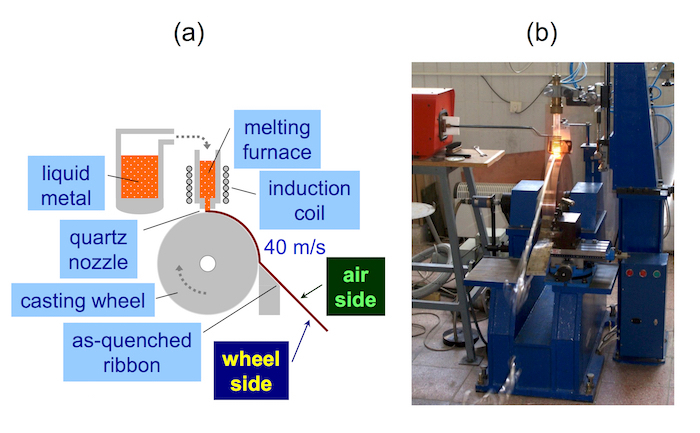
- Use an apparatus for planar flow casting. An example of such a device is shown in Figure 1. NOTE: The melt inside a quartz tube is expelled by Ar flow onto a quenching wheel which rotates in the air. There is no need for special atmospheric conditions under which the quenching wheel is operated (e.g., vacuum or inert gas environment) for this composition of the melt.
- Because of small weight of the ingot (~1.5 g), choose a quartz tube with a nozzle that has a round orifice of 0.8 mm in diameter. Put the ingot inside and melt it using inductive heating. Keep the temperature of the melt at 1,280-1,295 °C.
- Adjust the surface speed of the cooling wheel to 40 m/s.
- Cast the melt upon the rotating quenching wheel under ambient conditions, i.e., in the air. NOTE: The resulting ribbon is about 1.5-2 mm wide, 25-27 µm thick, and 5 m long. The air side of the ribbon, which was exposed during the production to the surrounding air atmosphere, is optically shiny (glossy) while the opposite wheel side, which was in direct contact with the quenching wheel, is mat (dull). These subtle ribbon qualities result from the low mass of the melt. Thus, it is important to verify the final chemical composition of the produced as-quenched ribbon because of the low input masses of the individual elements.
- Verification of the final chemical composition of the ribbon
- Prepare several (up to five) short pieces of the ribbon, each having a mass of about 0.70 mg. Chose them from different parts of the produced ribbon along its length.
- Dissolve every single piece of ribbon in 1 mL of concentrated (67%) HNO3 acid and fill with water to reach 50 mL total volume of the solution.
- Determine the content of Mo and B by optical emission spectrometry with inductively coupled plasma (OES-ICP). Use the method of external calibration as provided in the instrument's manual. Record the signals at the following wavelengths: Mo at 203.844 nm and 204.598 nm, and B at 249.773 nm.
- Determine the content of Fe, Co, and Cu by flame atomic absorption spectrometry (F-AAS). Use the method of external calibration as provided in the instrument's manual, and select these wavelengths: Fe at 248.3 nm, Co at 240.7 nm, and Cu at 324.7 nm.
- Structural characterization of the produced ribbons
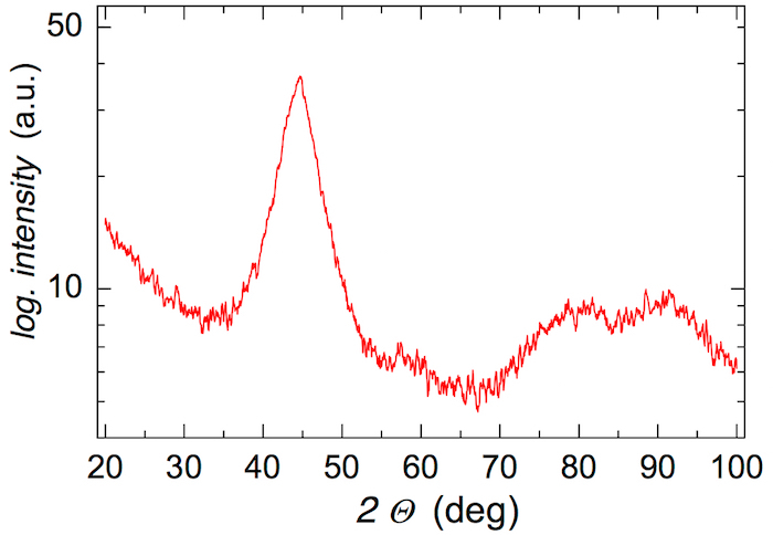
- Check the amorphous nature of the produced ribbons by performing X-ray diffraction (XRD) in Bragg-Brentano geometry; use the Cu anode with a wavelength of 0.154056 nm, record the diffraction pattern from 20-100° of 2Θ with an angular step of 0.05° and acquisition time of 20 s for one point. NOTE: The XRD diffractogram of an amorphous sample is characterized by broad reflection peaks like those shown in Figure 2. No narrow lines that indicate the presence of crystallites should be present.
- Prepare small pieces of the produced ribbons with a total mass of about 3-5 mg and place them into a graphite crucible of a DSC equipment. NOTE: Small pieces of about 2 mm in length can be cut off from the ribbon by scissors.
- Perform the DSC experiment with a temperature ramp of 10 K/min in a temperature range of 50-700 °C under Ar atmosphere.
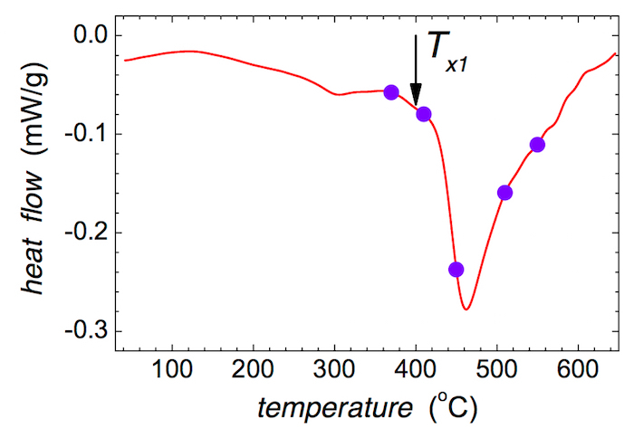
- Determine the temperature of the onset of crystallization Tx1, which is taken at the kink of the most pronounced peak on the DSC curve. NOTE: The temperature of the onset of crystallization Tx1 is indicated in Figure 3 by an arrow.
- Chose five temperatures of annealing that cover both the pre-crystallization and crystallization regions on the DSC for further ex situ annealing. NOTE: In our case, appropriate temperatures are 370, 410, 450, 510, and 550 °C as shown in Figure 3.
- Ex situ annealing
- Prepare five groups of ~ 7 cm long pieces (the total length) of the as-quenched ribbon. The individual ribbons should be at least 1 cm long.
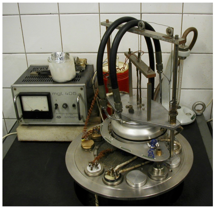
- For ex situ annealing, use a furnace (Figure 4). Set up the destination temperature and wait for 15 min for its stabilization. NOTE: The furnace design ensures minimal onset times for isothermal annealing. This furnace consists of two parts: upper and lower round massive nickel-plated copper blocks that act as a temperature homogenizer. Kanthal A strips heat up the blocks with high dynamics of temperature regulation and stabilization. The destination temperature is that determined in step 1.4.5.
- Insert pieces of the ribbon into the evacuated and thermally stabilized zone. To do this, open a 7-10 mm gap between the two blocks and slide the ribbons directly into the center of the heated zone.
- Close the gap immediately. In this way, the temperature of the sample achieves the furnace temperature in less than 5 s within a 0.1 K difference.
- Perform the annealing at 370, 410, 450, 510, and 550 °C for 30 min under vacuum to prevent surface oxidation.
- After annealing, remove the heated ribbons and place them on a cold substrate inside the vacuum system. This ensures fast cooling of the samples to room temperature. NOTE: Thermal treatment of the as-quenched ribbons induces structural changes that eventually lead to crystallization of the originally amorphous material.
2. Methods of Investigation
- Mössbauer spectrometry NOTE: The use of iron enriched to about 50% in 57Fe for production of the studied MG ensures sufficiently short acquisition times for in situ NFS experiments. On the other hand, the effective thickness of the ribbons is significantly increased. This poses issues related to extremely high broadening of the absorption Mössbauer spectral lines recorded in a conventional transmission geometry experiment. That is why surface sensitive techniques of Mössbauer spectrometry should be considered. Namely, Conversion Electron Mössbauer Spectrometry (CEMS) and Conversion X-ray Mössbauer Spectrometry (CXMS) can be applied. While CEMS scans subsurface regions to the depth of about 200 nm, CXMS provides information from deeper areas that extend down to about 5-10 µm.
- Prepare the samples for CEMS/CXMS experiments; use 6-8 pieces of ~ 1 cm long ribbons for one sample.
- Attach the ribbons side-by-side to an aluminum holder to form a compact area of about 1 x 1 cm2; use adhesive tape over the ends of the ribbons; all ribbons must be placed with their air sides upwards. NOTE: Ensure that there is an electric contact between the ribbons and the holder and that the central part of the sample (about 8 x 10 mm2) is clean from any surface contamination, e.g., remains of the adhesive tape.
- Insert the aluminum holder with the sample into the CEMS/CXMS detector.
- Prior to the measurement, thoroughly wash the inner detector volume with a stream of the detection gas to expel all residual air. Allow 10-15 min to accomplish this procedure.
- Adjust the gas flow through the detector by a needle valve to 3 mL/min.
- Connect a high voltage to the detector: a typical value is about 1.2 kV for CEMS and about 200 V higher for CXMS.
- Record the CEMS and CXMS Mössbauer spectra using a constant acceleration spectrometer equipped with a 57Co/Rh radioactive source. Operate the spectrometer with a gas detector at room temperature according to the manual.
- Accomplish the detection of conversion electrons and X-rays by a gas detector filled with a He+CH4 and Ar+CH4 gas mixture, respectively. Keep the amount of CH4 at 10% in both cases.
- Repeat steps 2.1.2 to 2.1.8 for the wheel side of the investigated ribbons.
- Perform velocity calibration14 of the apparatus by using a thin (12.5 µm) α-Fe foil.
- Evaluate the CEMS/CXMS spectra; quote the obtained isomer shift values with respect to a room temperature Mössbauer spectrum of the calibration α-Fe foil. NOTE: The obtained Mössbauer spectra can be evaluated by any suitable fitting code, for example by the Confit software24.
- NFS
- Accomplish the NFS experiments using a suitable nuclear resonance beamline at a synchrotron. A possible option: ID 18 at the European Synchrotron Radiation Facility (ESRF) in Grenoble, France.25
- Tune the energy of the photon beam to 14.413 keV with a bandwidth of ~ 1 meV.
- Place an approximately 6 mm long ribbon of the investigated MG in a vacuum furnace.
- Record the NFS time-domain patterns during continuous heating of the sample to a temperature of up to 700 °C with a ramp of 10 K/min. Use 1-min time intervals for acquisition of experimental data during the entire in situ annealing process. NOTE: The transmission geometry of the NFS experiment ensures that information on hyperfine interactions is obtained from the sample's bulk.
- Evaluate the NFS experimental data using a suitable software (e.g., www.nrixs.com). NOTE: During one in situ experiment, typically up to 100 NFS time-domain patterns are recorded. During their evaluation by the CONUSS software package26,27, consider the application of a special free software called Hubert that can evaluate such enormous data quantities in a semi-automatic mode28.
Representative Results
The XRD pattern in Figure 2 exhibits broad featureless diffraction peaks. The observed reflections demonstrate that the produced ribbon of the (Fe2.85Co1)77Mo8Cu1B14 MG is XRD amorphous.
Due to its sensitivity, XRD has some limitations in unveiling surface crystallization. The presence of crystallites amounting to less than about 2-3% of the MG is not critical. Thus, the term 'XRD amorphous' is sometimes used.
The initial decrease in the DSC recorded in Figure 3 is caused by the structural relaxation of the as-quenched MG, which takes place during heat treatment at moderate temperatures of up to ~ 400 °C. The following pronounced decrease of the DSC signal corresponds to the first step of crystallization. The temperature of the crystallization onset is about 400 °C with the ramp of 10 K/min. The selected temperatures of annealing are indicated by solid circles.
Well-defined positions of the resonant iron atoms in a crystalline lattice, which exhibit long-range order translation symmetry over several lattice constants, provide narrow spectral lines in the corresponding Mössbauer spectra. They feature discrete values of the spectral parameters which are unique for individual structural arrangements and, in this way, they act as fingerprints for the identification of different crystalline phases.
On the other hand, non-equivalent atomic positions in disordered amorphous materials cause broadening of the spectral lines. Thus, the associated spectral parameters exhibit distributions of their respective values. Distributions of the hyperfine spectral parameters provide information on the short-range order, i.e., the local atomic arrangement of the resonant atoms. Accordingly, Mössbauer spectrometry allows direct identification of the type of structural arrangement, specifically, crystalline (CR) versus amorphous (AM) as shown in Figure 5.
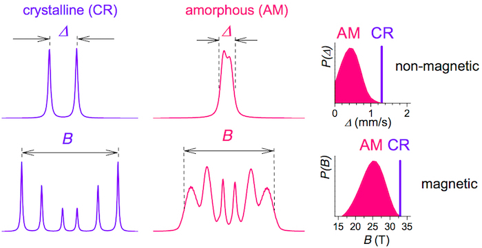
Both narrow and broad spectral lines occur in the Mössbauer spectra of NCA which are obtained from MGs by heat treatment. Moreover, the type of hyperfine interactions including quadrupole splitting (Δ) of a doublet and hyperfine magnetic fields (B) of a sextet can distinguish between non-magnetic and magnetic samples, respectively. In the case of amorphous samples, the corresponding distributions P(Δ) and P(B) are obtained.
In general, amorphous regions in the investigated samples can be of magnetic or paramagnetic origin. They are modeled by distributions of hyperfine magnetic fields P(B) and distributions of quadrupole splitting P(Δ), respectively. In our case, the as-quenched state of (Fe2.85Co1)77Mo8Cu1B14 MG is magnetic, but paramagnetic regions evolve inside the magnetic matrix after moderate heat treatment (up to the onset of crystallization).
After the onset of crystallization, newly formed nanocrystallites emerge in the residual amorphous matrix. The latter shows the same features as in the as-quenched state, i.e., the presence of magnetic and non-magnetic regions. In addition, atoms that are located at the surfaces of the nanograins exhibit perturbed symmetry. From one side, they experience perfect order of a crystalline lattice; from the other side they are in contact with the disordered amorphous matrix. Consequently, these atoms form a sort of interface between the amorphous rest and the crystallites. Thus, they were modeled by an additional distribution of hyperfine magnetic fields P(B) because this component is highly magnetic29.
The employed fitting software24 constructs the distributions as a convolution of the determining sextet or doublet of Lorentzian lines (with a Mössbauer line width of 0.195 mm/s) with Gaussians. We have used up to three Gaussians to account for the observed asymmetry of the spectra. Isomer shift, hyperfine magnetic field, or quadrupole splitting as well as the area of the determining sextet or doublet were fitted parameters. Line intensities of the 2nd and the 5th lines of the sextets were fitted, and the line intensity ratio of the lines (1+6):(3+4) was fixed to 3:1. The widths (standard deviations) of the individual Gauss distributions were fitted.
In all Mössbauer spectra, the presence of only the magnetically split crystalline components was observed. They were fitted with individual sextets of Lorentzian lines. The fitted parameters included isomer shift, hyperfine magnetic field, line width, intensity of the 2nd and the 5th lines, and the area of the component. Line intensity ratio of the lines (1+6):(3+4) was fixed to 3:1.
In some spectra, as many as six individual sextets were used. Here, two sextets were assigned to magnetic oxides. We have used up to four sextets to represent the newly formed nanograins in the annealed samples. The corresponding crystalline phase is that of bcc-Fe,Co in which Co replaces Fe at some lattice sites. Taking into consideration the binomial distribution of the most probable number of Co nearest neighbors, up to four sextets were used to model this situation depending also on the total crystalline contents in the individual annealed samples.
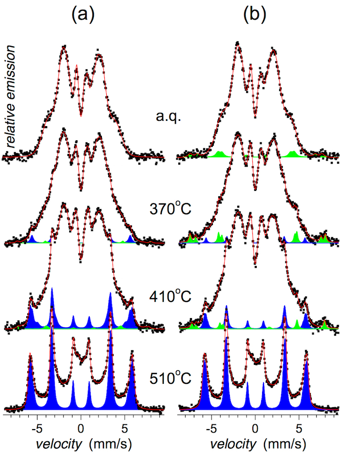
CEMS spectra taken from the near surface regions (to the depth of about 200 nm) reflect the structural arrangement that was induced by a 30-min annealing at the chosen temperature. CEMS spectra taken from the air and wheel sides of the ribbons at room temperature are shown in Figure 6.
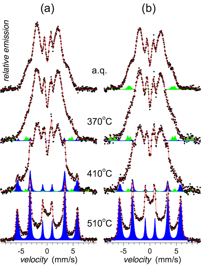
CXMS spectra that illustrate structural arrangement of the investigated MG in deeper subsurface regions (down to about 5-10 µm) are shown in Figure 7.
Relative areas of spectral components corresponding to crystalline phases are plotted as a function of annealing temperature in Figure 8 as derived from both methods.
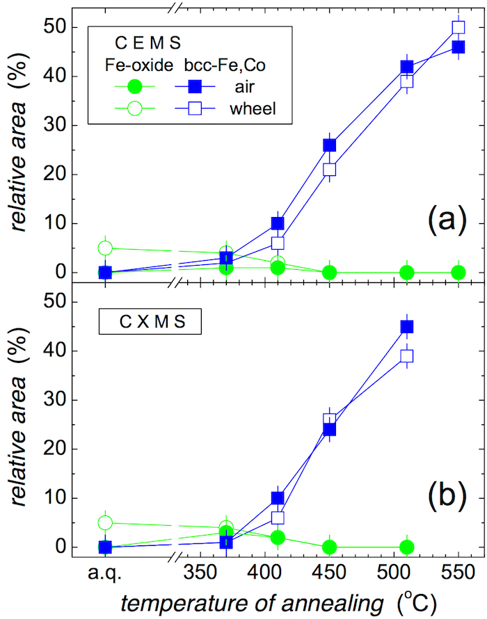
Well distinguished narrow Mössbauer lines in Figure 6 and Figure 7 indicate the formation of bcc-Fe,Co crystalline grains that appear after annealing at 410 °C. With the rising temperature of annealing, their amount progressively increases as shown in Figure 8. They are identified in close to surface layers by CEMS as well as in deeper regions by CXMS.
Traces of narrow Mössbauer lines are revealed also after low temperature of annealing and even in the as-quenched state, namely at the wheel side (see Figure 6b and Figure 7b). They belong to Fe oxides of corrosion products. During the production process, some humid air is trapped between the melt and the quenching wheel. The humidity immediately evaporates and forms air pockets inside which corrosion might be initiated. The Mössbauer signal from this component is very weak and after annealing at higher temperatures it is overlapped with that of the emerging bcc-Fe,Co nanocrystals. It is noteworthy that the identification of the corrosion products was enabled mainly due to high content of 57Fe in these samples. Should a natural iron be used for their production, this spectral component would not have been detected. In this respect, Mössbauer spectrometry is more sensitive for the identification of iron-containing crystalline phases than for example, XRD.
It should be noted that narrow Mössbauer lines, which indicate a presence of nanocrystallites, are well distinguished after annealing at 410 °C. Nevertheless, traces of these lines are revealed also after annealing at 370 °C, which is a lower temperature than Tx1 suggested by DSC. They are more pronounced on the air side where the quenching conditions are not so effective as on the wheel side. Thus, the crystallization has started on this surface of the ribbons.
Mössbauer spectra of the bcc-Fe,Co crystalline phase were evaluated using four narrow sextets marked as Co0, Co1, Co2, and Co3. They represent Fe positions with zero, one, two, and three Co nearest neighbors, correspondingly. The obtained hyperfine magnetic fields are shown in Figure 9. With increasing number of Co atoms, the hyperfine magnetic fields at Fe sites increase. They were averaged over all annealing temperatures for individual methods, that is, CEMS and CXMS applied to both sides of the ribbons. Finally, the average of the four partial values was obtained. The resulting hyperfine magnetic fields are plotted in Figure 9a.
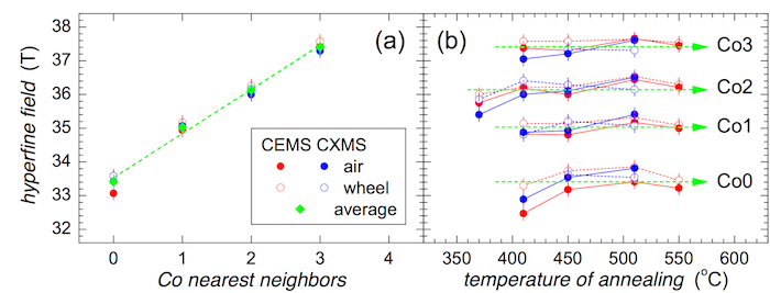
The evolution of the hyperfine magnetic fields, which correspond to a different number of Co nearest neighbors, is plotted in Figure 9b against the annealing temperature. They are scattered around the average values taken from Figure 9a. Notable deviations are observed for Co0 and Co2 at low annealing temperatures. It is noteworthy that the Co2 component has appeared even after annealing at 370 °C. This indicates that bcc-Fe,Co nanocrystals start to grow already at this temperature. The associated hyperfine magnetic fields diverge from the average mainly due to the size effects of the newly formed grains. This spectral component was identified as the only one because of its highest probability in a binomial distribution.
After annealing at 410 °C, the crystallization at the surface of the ribbon is well documented (see also Figure 8). The corresponding spectral components exhibit stable hyperfine magnetic fields except one - Co0. Fe positions with zero Co nearest neighbors only begin to appear because their probability is relatively low (probability of Co0 is 0.09 while that of Co2 is 0.31). Consequently, their hyperfine magnetic field values are also affected.
Ex situ Mössbauer spectrometry is a suitable method for identifying the type of crystalline phase(s) produced by heat treatment of an as-quenched MG. Moreover, because it probes the hyperfine interactions it can distinguish among lattice sites with a different number of substitution atoms.
Nuclear resonant scattering can be effectively accomplished with synchrotron radiation featuring extremely high brilliance and tunable energy30. The choice of the appropriate energy that matches with separation of nuclear levels in 57Fe enables the involvement of NFS for many experimental studies in materials research31. In fact, this technique can be considered analogous to Mössbauer spectrometry32.
Pulses of synchrotron radiation with a typical duration of ~ 50 ps provide photons with a bandwidth of several meV. Because hyperfine interactions are on the order of several neV, such a pulse excites simultaneously all possible transitions among the nuclear levels. Consequent deexcitation photons are coherent and interfere with one another. In contrast, in conventional Mössbauer spectrometry both excitation and deexcitation are activated sequentially when the unique energy of photons released from a radioactive source is modulated via the Doppler effect to the requested energy. The interference of photons is schematically drawn in Figure 10.
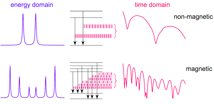
NFS time-domain patterns represent plots of the number of photons emitted by the sample as a function of a delayed time. The latter is a time that has elapsed from the excitation of nuclear levels with a synchrotron-radiation pulse until the detection of these 'delayed' photons.
Depending upon the temperature of measurement, three separate temperature regions can be distinguished. Consequently, we have employed three fitting models which take into consideration the temperature evolution of hyperfine interactions and accompanying structural transformations within the individual temperature regions.
In the first region which comprises low temperatures up to the Curie point, the investigated MG is amorphous and exhibits magnetic interactions. The corresponding physical model consisted of two distributions of hyperfine magnetic fields. They were assigned to two types of short-range order (SRO) arrangements representing amorphous regions with rather high (~ 22 T) and low (~ 8 T) average hyperfine magnetic fields (at room temperature). Values of the average hyperfine magnetic fields corresponding to both distributions were fitted. Relative contributions of both components were fitted only in the NFS time-domain pattern, which was recorded at room temperature. For increasing temperature of the in situ experiments, their relative ratio was kept fixed.
In the second, i.e., intermediate temperature region between the Curie point and the onset of the first crystallization, the investigated MG is still amorphous but already paramagnetic. The resulting structure is modeled by a single distribution of quadrupole splitting. Thus, only its average value was fitted.
After the onset of the first crystallization, i.e., in the high temperature region, the formation of bcc-Fe,Co nanograins begins. They are embedded in a residual amorphous matrix that is paramagnetic due to the considerably high temperature of the experiment. Consequently, the third fitting model consisted of a distribution of quadrupole splitting which was the same as in the previous case. The presence of nanograins was accounted for by the additional four magnetic components with unique values of hyperfine magnetic fields (i.e., not distributed). Their relative fractions were derived from a binomial distribution of the Co nearest neighbors similar as in the case of conventional Mössbauer spectrometry. The contribution of other crystallites was not identified in the bulk of the sample and that is why no additional magnetic components were needed. The fitted parameters included relative contribution of the nanocrystalline phase and the amorphous residual matrix, the average quadrupole splitting of the latter phase, and four values of hyperfine magnetic fields assigned to the individual crystallographic sites. The obtained temperature evolutions of the fitted parameters are presented in separate figures below for all three regions.
Before evaluating the experimental data, five adjacent points were summed to increase the counted intensity and thus, improve the signal-to-noise ratio. Considering that the time resolution of the used avalanche photo diode detector is greater than 0.1 ns, such data treatment caused diminution of the detector's resolution to about 0.5 ns, which is still satisfactory for the determination of hyperfine parameters. In addition, the used detector exhibits negligible background count rate in comparison to the NFS signal. Consequently, the background parameter was kept at zero during the evaluation procedure.
The NFS experiments were performed during the continuous increase of temperature which was rising at a rate of 10 K/min. The acquisition of the data was also continuous, and the NFS time-domain patterns were stored at the end of every minute. During one experiment, several tens of individual NFS time-domain records were collected. In this way, a progress of structural transformations that are taking place in the whole bulk of the investigated MG can be followed in situ with respect to the time and/or temperature.
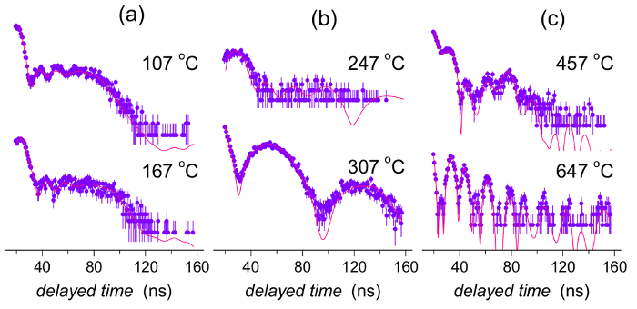
Examples of individual NFS time-domain patterns are shown in Figure 11 where the experimental data (full dots with errors) and theoretically calculated curves (solid lines) are given. The latter were evaluated using different fitting models for different temperature intervals as described above. Note that the y-axes are given in logarithmic scale. Thus, even small deviations between the experimental points and the theoretically calculated curves are visually enhanced. Nevertheless, because of the rather low counts especially in longer delayed time regions, where also some differences occur, their effect upon the resulting hyperfine interactions is negligible.
All NFS patterns are presented in Figure 12 by contour plot. Delayed time of resonantly scattered photons constitutes the abscissa, and the heating temperature during acquisition of NFS data experiment is given on the y-axis. The intensities of the records are color-coded in logarithmic scale.
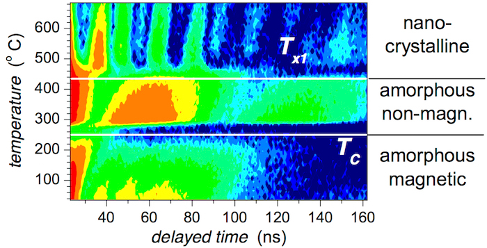
Obvious deviations in the shapes of NFS records in Figure 11 and Figure 12 clearly indicate changes in hyperfine interactions observed at certain temperatures. The Curie temperature TC corresponds to the transition from ferromagnetic to paramagnetic arrangement of the studied MG. It is a phase transition of the second order. From a structural point of view, however, the system is still amorphous.
A dramatic change in the shapes of NFS time-domain records at Tx1 relates to the onset of crystallization when nanocrystallites emerge from the amorphous matrix. This structural transformation is accompanied by the re-appearance of magnetic hyperfine interactions. They are established among the newly formed bcc-Fe,Co nanograins. Even with the rising temperature of the experiment, the ferromagnetic order survives.
The evolution of hyperfine magnetic fields at the nanocrystals and their relative amount with temperature are shown in Figure 13a and Figure 13b, respectively. Note that due to high sensitivity of NFS, the presence of a different number of Co atoms that are incorporated into the bcc lattice as the nearest neighbors of Fe atoms can be distinguished via differences in their hyperfine magnetic fields. They are denoted as Co0 to Co3 in Figure 13 and correspond to zero, one, two, and three Co nearest neighbors.
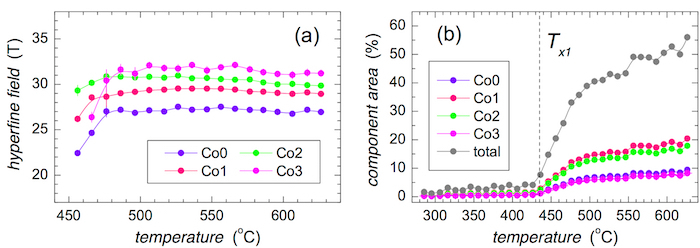
Rather small values of hyperfine magnetic fields that are observed in Figure 13a at the beginning of crystallization are due to the size effect of evolving crystalline grains. Their lattice gradually acquires its final order which also determines the corresponding hyperfine magnetic fields. After reaching the temperature of approximately 500 °C, the latter are stabilized and their values are governed exclusively by the variations of temperature. The almost unnoticeable slow decrease of hyperfine magnetic fields with rising temperature of the experiment suggests a rather high value of the Curie temperature of the newly formed crystalline phase.
The number of nanocrystals progressively increases for T > Tx1 as demonstrated in Figure 13b. The temperature evolution of the individual fitting components is also displayed. In this case, the size of symbols is higher than the corresponding error range. It is noteworthy that the components denoted as Co0 and Co3 exhibit very similar values. This is caused by the low probabilities of zero and three Co nearest neighbors as derived from the associated binomial distribution.
The temperature development of hyperfine magnetic and quadrupole electric interactions inside the amorphous matrix is demonstrated in Figure 14. In the low temperature region where T < TC, an expected temperature driven decrease in hyperfine fields of both evaluation components is observed in Figure 14a. Here, the fitting model consists of two distributions of hyperfine magnetic fields.
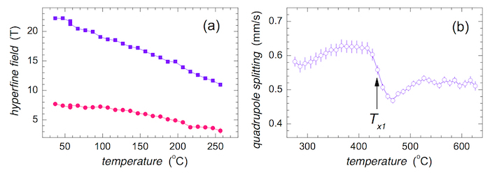
The whole MG is amorphous, though non-magnetic, until the onset of crystallization at Tx1. After that, the nanocrystalline grains emerge but the residual amorphous matrix is still non-magnetic. Consequently, the amorphous part of the alloy is reproduced by one distribution of quadrupole splitting and the obtained average values are plotted in Figure 14b against temperature. An abrupt change in this parameter is seen near Tx1. The latter was determined as an inflection point of the curve.
The evolution of the total number of counts (areas) of the individual NFS time-domain patterns with respect to temperature of the in situ NFS experiment is shown in Figure 15. It can be used for the characterization of the investigated system even without any need for precise evaluation of the individual parameters. Three well-distinguished regions can be identified. They are separated by characteristic temperatures TC and Tx1. Note that at TC, the NFS signal has almost vanished.
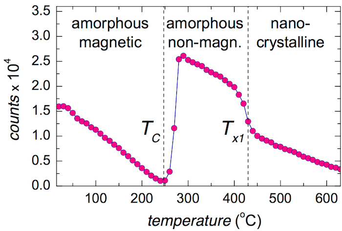
The initial decrease of the total counts toward TC reflects the temperature reduction of hyperfine magnetic fields in the amorphous phase. Consequently, the originally well resolved sextet, that is observed in the energy domain, eventually collapses at TC to poorly resolved broad single-line signal, i.e., when the dipolar magnetic interactions completely vanish. In the time domain, the absorbed and re-emitted photons interfere after the excitation pulse. Because the energy and the time domains are coupled via the Fourier transformation, some consequences should be considered. For example, broad lines in the energy domain are represented by rapidly decaying signal in the time domain and vice versa. Thus, at TC the time signal is squeezed into a very narrow time interval just after the excitation pulse as demonstrated by the upper pattern in Figure 11b. Here, the relevant experimental data are seen only during the first 40 ns. The possible evolution of the time signal for longer times is documented only by the theoretically calculated curve.
It should be noted that all time-domain patterns start only 20 ns after the excitation pulse. This is because of the extremely high number of prompt and delayed photons that might seriously damage the used detectors. That is why the detectors are electronically gated and do not register the incoming photons during the initial 20 ns. Nevertheless, after the transition into the paramagnetic state, the qualitatively new hyperfine interactions emerge that provide rather narrow lines in the energy domain and, thus, the corresponding time-domain signal decays more slowly. As a result, well-established quantum beat patterns appear as shown by the lower pattern in Figure 11b and the total number of counts in Figure 15 has dramatically increased.
The subsequent fall of counts (namely after Tx1) can be ascribed mainly to the formation of nanocrystallites that are strongly ferromagnetic featuring dipolar magnetic interactions. The corresponding time-domain patterns are represented by many high-frequency beats which, however, encompass a lower area than those of a still partially amorphous phase (see Figure 11c).
After reaching the destination temperature of 700 °C, the NFS experiment continued with time dwell for 10 min at this temperature and subsequent cooling. The recorded time-domain patterns are shown in Figure 16 with respect to the time of experiment. Within the isothermal region, the shape of the NFS time-domain patterns does not change substantially. Only a moderate increase in intensity of some peaks is observed. This is attributed to the evolution of crystalline grains which grow with time. Consequently, their corresponding hyperfine interactions rise in intensity, which is clearly seen in the isothermal region in Figure 16.
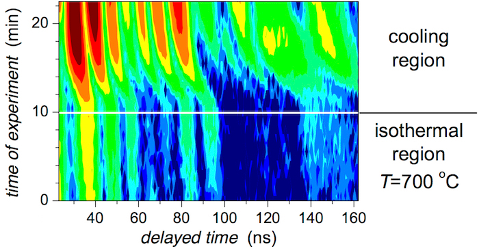
During the cooling, the NFS peaks move towards their final positions that are expected at room temperature. At the same time, their intensities also rise due to increase in the probability of the resonance effect with decreasing temperature. These changes can be seen after the 10th min of the experiment in the upper half of Figure 16 (i.e., the cooling region).
Figure 1: Apparatus for planar flow casting. (a) Schematic diagram and (b) photo of a real device. Please click here to view a larger version of this figure.
Figure 2: XRD of the as-quenched (Fe2.85Co1)77Mo8Cu1B14 metallic glass. Broad featureless reflections indicate that the ribbon is XRD amorphous. Please click here to view a larger version of this figure.
Figure 3: DSC record of the as-quenched (Fe2.85Co1)77Mo8Cu1B14 metallic glass. Solid circles indicate the intended temperatures of annealing; the temperature of the onset of crystallization Tx1 is marked with the arrow. Please click here to view a larger version of this figure.
Figure 4: Apparatus for ex situ heat treatment of the as-quenched metallic glass ribbons. Please click here to view a larger version of this figure.
Figure 5: Model Mössbauer spectra. Crystalline (CR) materials exhibit narrow Mössbauer lines (left) which provide discrete values of hyperfine interactions (right). Amorphous (AM) materials are characterized by broad lines (middle) and distributions of non-magnetic P(Δ) and magnetic P(B) hyperfine interactions. This figure has been modified from [23]. Please click here to view a larger version of this figure.
Figure 6: CEMS spectra of the (Fe2.85Co1)77Mo8Cu1B14 metallic glass. Spectra were taken from (a) the air side and (b) the wheel side of the ribbons annealed at the indicated temperatures (a.q. = as-quenched). Mössbauer spectral lines corresponding to crystalline phases are plotted in blue (bcc-Fe,Co) and green (Fe oxides). This figure has been modified from [23]. Please click here to view a larger version of this figure.
Figure 7: CXMS spectra of the (Fe2.85Co1)77Mo8Cu1B14 metallic glass. Spectra were taken from (a) the air side and (b) the wheel side of the ribbons annealed at the indicated temperatures (a.q. = as-quenched). Mössbauer spectral lines corresponding to crystalline phases are plotted in blue (bcc-Fe,Co) and green (Fe oxides). This figure has been modified from [23]. Please click here to view a larger version of this figure.
Figure 8: Relative areas of the Mössbauer spectral components plotted against temperature of annealing. Components correspond to Fe-oxide (circles) and bcc-Fe,Co (squares). They were derived from (a) CEMS and (b) CXMS spectra of the (Fe2.85Co1)77Mo8Cu1B14 metallic glass taken from the air (full symbols) and wheel (open symbols) sides of the ribbons (a.q. = as-quenched). This figure has been modified from [23]. Please click here to view a larger version of this figure.
Figure 9: Hyperfine magnetic fields of the crystalline component. Hyperfine magnetic fields obtained from CEMS (red symbols) and CXMS (blue symbols) spectra of the (Fe2.85Co1)77Mo8Cu1B14 metallic glass plotted against (a) number of Co nearest neighbors in a bcc lattice and (b) temperature of annealing. Spectra were taken from the air side (full symbols) and wheel side (open symbols). Average values of hyperfine fields are plotted by green symbols and dashed lines. Please click here to view a larger version of this figure.
Figure 10: Comparison of Mössbauer spectra and NFS time-domain patterns. Sequential recording of nuclear transitions among split nuclear levels (middle) gives rise to Mössbauer spectra (left) in the energy domain. During simultaneous excitation by a single pulse of incident synchrotron radiation, the subsequent de-excitation photons of different energies interfere and provide a NFS time-domain pattern (right). The effect of the non-magnetic and magnetic hyperfine interactions is also compared. This figure has been modified from [23]. Please click here to view a larger version of this figure.
Figure 11: Examples of selected NFS time-domain patterns of the (Fe2.85Co1)77Mo8Cu1B14 metallic glass. Experimental data plotted by full symbols (including error range) are refined by theoretically calculated curves (solid lines). NFS data were taken at the indicated temperatures and comprise different temperature ranges: (a) below the Curie point, (b) between the Curie point and the onset of crystallization, and (c) beyond the onset of crystallization. This figure has been modified from [23]. Please click here to view a larger version of this figure.
Figure 12: Contour plot of NFS time-domain patterns of the (Fe2.85Co1)77Mo8Cu1B14 metallic glass taken during in situ temperature experiment. Transition temperatures including the Curie point (TC) and the onset of crystallization (Tx1) divide the whole temperature range into three distinguished intervals. This figure has been modified from [23]. Please click here to view a larger version of this figure.
Figure 13: NFS in situ experiment on the (Fe2.85Co1)77Mo8Cu1B14 metallic glass. Parameters of the time-domain patterns that correspond to the crystalline phase plotted against the temperature of measurement: (a) hyperfine magnetic fields and (b) relative areas of specific atomic sites in bcc-Fe,Co lattice featuring 0, 1, 2, and 3 Co nearest neighbors of Fe atoms. This figure has been modified from [21] with permission from the PCCP Owner Societies. Please click here to view a larger version of this figure.
Figure 14: NFS in situ experiment on the (Fe2.85Co1)77Mo8Cu1B14 metallic glass. Hyperfine parameters of the residual amorphous matrix plotted against temperature of measurement: (a) average hyperfine magnetic fields and (b) average quadrupole splitting. The parameters were refined by specific fitting models applied for different temperature regions. Temperature of the onset of crystallization (Tx1) is marked with an arrow. This figure has been modified from [23]. Please click here to view a larger version of this figure.
Figure 15: NFS in situ experiment on the (Fe2.85Co1)77Mo8Cu1B14 metallic glass. Total area of NFS time-domain patterns plotted against temperature of measurement. Distinguished temperature transitions are labeled with TC (Curie point) and Tx1 (onset of crystallization) and marked with arrows. ©2017 Marcel B. Miglierini and Vít Procházka Adapted from ref. [22]; originally published under CC BY-NC 4.0 license. Available from: DOI: 10.5772/66869. Please click here to view a larger version of this figure.
Figure 16: Contour plot of NFS time-domain patterns of the (Fe2.85Co1)77Mo8Cu1B14 metallic glass taken after temperature heating. NFS time-domain patterns were recorded during a 10-min dwell after reaching the destination temperature of 700 °C and consequent cooling. Note the y-coordinate which is the time of experiment. Please click here to view a larger version of this figure.
Discussion
Ex situ Mössbauer effect experiments describe a steady situation which is encountered in the investigated MG after the applied heat treatment. Each spectrum was collected for a duration of several hours at room temperature. Thus, the evolution of the originally amorphous structure was followed as a function of annealing conditions. Because Mössbauer spectrometry is sensitive to hyperfine interactions acting upon the resonant nuclei, faint details of structural and/or magnetic modifications induced by elevated temperature can be unveiled. Nevertheless, the investigated samples are inspected under ambient conditions when the influence of temporarily changed conditions (e.g., temperature increase) is already finished.
In situ NFS experiments examine the studied MG in the dynamic mode during their exposure to varying temperature. This opens a qualitatively new insight into the behavior of the system of interest, a MG in this case. It is noteworthy that the NFS data are acquired within one minute. This allows real-time inspection of the evolution of hyperfine interactions. This is almost impossible by conventional Mössbauer spectrometry. We should admit, however, that the obtained parameters are averaged over one-minute intervals during which the data are recorded. Nevertheless, possible variations in the individual parameters during such a short time span can be considered negligible.
Both Mössbauer spectrometry and NFS probe local neighborhoods of Fe resonant atoms via hyperfine interactions. Consequently, information on structural arrangement and magnetic microstructure is simultaneously available. This is especially important when complex systems like NCA are investigated. As we have demonstrated, it is possible not only to follow magnetic transition from ferromagnetic to paramagnetic arrangement but also consequent structural transformation, i.e., crystallization. The formation of nanograins can be inspected under both the steady and transient conditions. Moreover, their detailed characterization featuring identification of individual lattice sites with varying number of foreign atoms in a bcc structure is also feasible.
Ex situ experiments performed by the conventional Mossbauer spectroscopy provide information on steady states of the material including both stable and metastable states. This means that we can investigate the local structural as well as magnetic arrangements in the initial (as-quenched) material and in the final product, too. The latter is obtained via nanocrystallization of the former after suitable heat treatment but measured at ambient conditions. However, ex situ Mössbauer spectrometry provides information in the energy domain. Thus, the obtained spectra are directly related to the state of the investigated material and more convenient for evaluation and interpretation.
On the other hand, in situ NFS approach is suitable for investigating transient processes that are occurring during phase transformations. Because the information on the material's arrangement is encoded in quantum beats recorded in the time domain, the evaluation of NFS patterns is a challenging task. It can be solved by proper use of the results obtained from ex situ Mössbauer effect experiments. Thus, the combination of both methods enables the inspection of the steady as well as transient states of the investigated system.
Both techniques are complementary from the point of view of the obtained results as well as the conditions under which they were achieved. The obtained experience can be effectively used also in studies of other issues that are associated with structural and/or magnetic transitions. As a typical example, the existence of intermediate phases differing in the valence state of iron in the solid state reduction of Fe(VI) to Fe(III) oxides during temperature treatment can be mentioned33.
Disclosures
The authors have nothing to disclose.
Acknowledgments
This work was supported by the Slovak Research and Development Agency under the contracts No. APVV-16-0079 and APVV-15-0621, grants VEGA 1/0182/16 and VEGA 2/0082/17, and the internal IGA grant of Palacký University (IGA_PrF_2018_002). We are grateful to R. Rüffer (ESRF, Grenoble) for assistance with the synchrotron experiments.
References
- McHenry ME, Laughlin DE. Nano-scale materials development for future magnetic applications. Acta Mater. 2000;48(1):223–238. [Google Scholar]
- Chang Y-H, Hsu C-H, Chu H-L, Chang C-W, Chan W-S, Lee Ch-Y, Yao C-S, He Y-L. Effect of uneven surface on magnetic properties of Fe-based amorphous transformer. Int. J. Elect. Comp. Energetic, Electronic and Commun. Eng. 2011;5(8):1160–1164. [Google Scholar]
- Herzer G. Modern soft magnets: Amorphous and nanocrystalline materials. Acta Mater. 2013;61(3):718–734. [Google Scholar]
- Yoshizawa Y, Oguma A, Yamauchi K. New Fe-based soft magnetic-alloys composed of ultrafine grain-structure. J. Appl. Phys. 1988;64(10):6044–6046. [Google Scholar]
- Suzuki K, Kataoka N, Inoue A, Makino A, Masumoto T. High saturation magnetization and soft magnetic-properties of bcc Fe-Zr-B alloys with ultrafine grain-structure. Mater. Trans. JIM. 1990;31(8):743–746. [Google Scholar]
- Willard MA, Laughlin DE, McHenry ME, Thoma D, Sickafus K, Cross JO, Harris VG. Structure and magnetic properties of (Fe0.5Co0.5)(88)Zr7B4Cu1 nanocrystalline alloys. J. Appl. Phys. 1998;84(88):6773–6777. [Google Scholar]
- Makino A, Men H, Kubota T, Yubuta K, Inoue A. New Fe-metalloids based nanocrystalline alloys with high B-s of 1.9 T and excellent magnetic softness. J. Appl. Phys. 2009;105(7) [Google Scholar]
- Suzuki K, Herzer G. Magnetic-field-induced anisotropies and exchange softening in Fe-rich nanocrystalline soft magnetic alloys. Scripta Mater. 2012;67(6):548–553. [Google Scholar]
- Hasegawa R. Advances in amorphous and nanocrystalline materials. J. Magn. Magn. Mater. 2012;324(21):3555–3557. [Google Scholar]
- Hristoforou E, Reilly RE. Nonuniformity in amorphous ribbon delay lines after stress and current annealing. J. Appl. Phys. 1991;69(8):5008–5010. [Google Scholar]
- Hristoforou E, Niarchos D. Fast characterization of magnetostrictive delay-lines. IEEE Trans. Magn. 1993;29(6):3147–3149. [Google Scholar]
- Miglierini M, Lančok A, Kohout J. Hyperfine fields in nanocrystalline Fe-Zr-B probed by 57Fe nuclear magnetic resonance spectroscopy. Appl. Phys. Lett. 2010;96(21) [Google Scholar]
- Kohout J, Křišťan P, Kubániová D, Kmječ T, Závěta K, Štepánková H, Lančok A, Sklenka Ľ, Matúš P, Miglierini M. Low Temperature Behavior of Hyperfine Fields in Amorphous and Nanocrystalline FeMoCuB. J. Appl. Phys. 2015;117(17):1–17. [Google Scholar]
- Gütlich Ph, Bill E, Trautwein AX. Mössbauer Spectroscopy and Transition Metal Chemistry. Berlin, Heidelberg, Germany: Springer-Verlag; 2011. [Google Scholar]
- Stankov S, Sepiol B, Kaňuch T, Scherjau D, Würschum R, Miglierini M. High Temperature Mössbauer Effect Study of Fe90Zr7B3 Nanocrystalline Alloy. J. Phys.: Condens. Mat. 2005;17(21):3183–3196. [Google Scholar]
- Smirnov GV. General properties of nuclear resonant scattering. Hyperfine Int. 1999;123(1-8):31–77. [Google Scholar]
- Röhlsberger R. Nuclear Condensed Matter Physics with Synchrotron Radiation. Berlin, Heidelberg, Germany: Springer-Verlag; 2004. [Google Scholar]
- Miglierini M, Procházka V, Stankov S, Švec P, Sr, Zajac M, Kohout J, Lančok A, Janičkovič D, Švec P. Crystallization kinetics of nanocrystalline alloys revealed by in-situ nuclear forward scattering of synchrotron radiation. Phys. Rev. B. 2012;86(2) [Google Scholar]
- Miglierini M, Procházka V, Rüffer R, Zbořil R. In situ crystallization of metallic glasses during magnetic annealing. Acta Mater. 2015;91:50–56. [Google Scholar]
- Procházka V, Vrba V, Smrčka D, Rüffer R, Matúš P, Mašláň M, Miglierini M. Structural transformation of NANOPERM-type metallic glasses followed in situ by synchrotron radiation during thermal annealing in external magnetic field. J. Alloy. Compounds. 2015;638:398–404. [Google Scholar]
- Miglierini M, Pavlovič M, Procházka V, Hatala T, Schumacher G, Rüffer R. Evolution of structure and local magnetic fields during crystallization of HITPERM glassy alloys studied by in situ diffraction and nuclear forward scattering of synchrotron radiation. Phys. Chem. Chem. Phys. 2015;17(42):28239–28249. doi: 10.1039/c5cp00245a. [DOI] [PubMed] [Google Scholar]
- Miglierini MB, Procházka V. Nanocrystallization of Metallic Glasses Followed by in situ Nuclear Forward Scattering of Synchrotron Radiation. In: Khodaei M, Petaccia L, editors. X-ray Characterization of Nanomaterials by Synchrotron Radiation. Rjeka, Croatia: InTech; 2017. pp. 7–29. [Google Scholar]
- Miglierini M, Matúš P. Structural Modifications of Metallic Glasses Followed by Techniques of Nuclear Resonances. Pure Appl. Chem. 2017;89(4):405–417. [Google Scholar]
- Žák T, Jirásková Y. CONFIT: Mössbauer spectra fitting program. Surf. Interf. Anal. 2006;38(4):710–714. [Google Scholar]
- Rüffer R, Chumakov AI. Nuclear-resonance beamline at ESRF. Hyperfine Interact. 1996. pp. 589–604.
- Sturhahn W, Gerdau E. Evaluation of time-differential measurements of nuclear-resonance scattering. of X-rays Phys. Rev. B. 1994;49(14):9285–9294. doi: 10.1103/physrevb.49.9285. [DOI] [PubMed] [Google Scholar]
- Sturhahn W. CONUSS and PHOENIX: Evaluation of nuclear resonant scattering data. Hyperfine Interact. 2000;125(1-4):149–172. [Google Scholar]
- Vrba V, Procházka V, Smrčka D, Miglierini M. Advanced Approach to the Analysis of a Series of in-situ Nuclear Forward Scattering Experiments. Nucl. Instr. Meth. Phys. Res. A. 2017;847:111–116. [Google Scholar]
- Miglierini M, Grenèche J-M. Mössbauer Spectrometry of Fe(Cu)MB-Type Nanocrystalline Alloys: I. The Fitting Model for the Mössbauer Spectra. J. Phys.: Condens. Matter. 1997;9(10):2303–2319. [Google Scholar]
- Mülhaupt G, Rüffer R. Properties of synchrotron radiation. Hyperfine Int. 1999;123(1-8):13–30. [Google Scholar]
- Rüffer R. Nuclear resonance scattering. C. R. Physique. 2008;9(5-6):595–607. [Google Scholar]
- Seto M. Condensed matter physics using nuclear resonant scattering. J. Phys. Soc. Jpn. 2013;82(2):021016. [Google Scholar]
- Machala L, Procházka V, Miglierini M, Sharma VK, Marušák Z, Wille H-Ch, Zbořil R. Direct Evidence of Fe(V) and Fe(IV) Intermediates during Reduction of Fe(VI) to Fe(III): A Nuclear Forward Scattering of Synchrotron Radiation Approach. Phys. Chem. Chem. Phys. 2015;17(34):21787–21790. doi: 10.1039/c5cp03784k. [DOI] [PubMed] [Google Scholar]


