Abstract
The goal of this protocol is to present how to perform spin- and angle-resolved photoemission spectroscopy combined with polarization-variable 7-eV laser (laser-SARPES), and demonstrate a power of this technique for studying solid state physics. Laser-SARPES achieves two great capabilities. Firstly, by examining orbital selection rule of linearly polarized lasers, orbital selective excitation can be carried out in SAPRES experiment. Secondly, the technique can show full information of a variation of the spin quantum axis as a function of the light polarization. To demonstrate the power of the collaboration of these capabilities in laser-SARPES, we apply this technique for the investigations of spin-orbit coupled surface states of Bi2Se3. This technique affords to decompose spin and orbital components from the spin-orbit coupled wavefunctions. Moreover, as a representative advantage of using the direct spin detection collaborated with the polarization-variable laser, the technique unambiguously visualizes the light polarization dependence of the spin quantum axis in three-dimension. Laser-SARPES dramatically increases a capability of photoemission technique.
Keywords: Engineering, Issue 136, Solid state physics, band structure of solids, spin-orbit coupling, spin polarization, surface states, photoemission, spin-detector, laser
Introduction
Angle-resolved photoemission spectroscopy (ARPES) technique has developed into one of the most powerful tool to investigate quasiparticle band structures in solid states1. The most of attractive feature of ARPES is the capability for band mapping to characterize electronic states in energy and momentum space. Spin-resolved ARPES (SARPES), which is here equipped with spin-detectors, e.g. Mott detector2,3, further enables us to resolve the spin character of the observed band structures4. Since the Mott detector can measure the spin with two axes (x and z, or y and z), the combination of the two Mott detectors further allows one to obtain the spin orientation in three dimension4,5. For several decades, however, the SARPES experiments were suffered from their low efficiency (typically 1/10000 compared to that for spin-integrated ARPES measurement)3,4,5,6,7, which had limited the energy and angular-resolutions. Recently, the energy resolution of SARPES has been increased with a high-efficient spin detector based on exchange scattering, the so-called very-low-energy electron-diffraction (VLEED) detector7,8,9,10. With this detector, the data quality has been significantly improved and the data acquisition time has been shortened. Recently, SARPES has succeeded greatly to address spin-polarized electronic states and particularly spin-orbit coupling effect resulting in the spin texture of the surface bands7.
Here, we employ SARPES measurements with a polarization-variable vacuum ultraviolet laser light (laser-SARPES) and demonstrate the great advantages of this combined technique. Through the investigation on the spin-orbit coupled surface states in Bi2Se3, we present two capabilities of laser-SARPES. Firstly, due to the orbital selection rule of linearly polarized lasers in dipole transition regime, p- and s-polarized lights selectively excite a part of eigen-wavefunctions with different orbital symmetry. Such an orbital selective excitation is thereby available in SARPES, namely, orbital-selective SARPES. Secondly, three-dimensional (3D) spin-detection in SARPES shows the direction of the spin quantum axis and directly displays full information of the light-polarization dependence. In this protocol, we briefly describe a methodology to perform this state-of-the-art laser-SARPES technique to study the strong spin-orbit coupling effects.
Our laser-SARPES system is located at The Institute for Solid State Physics, The University of Tokyo11. The schematic drawing of our laser-SAPRES machine is shown in Figure 1. The polarization-variable 7-eV laser light12 illuminates the sample surface and the photoelectrons are emitted from the sample. The polarization of laser is automatically controlled by MgF2-based λ/2- and λ/4-waveplates to selectively use linear and circular polarizations. A hemispherical electron analyzer corrects the photoelectrons, and analyzes their kinetic energy (Ekin) and emission angle (θx and θy). The photoelectron intensities are mapped on the Ekin-θx screen monitored by a CCD camera. This image is directly transformed into the energy band structure in reciprocal space.
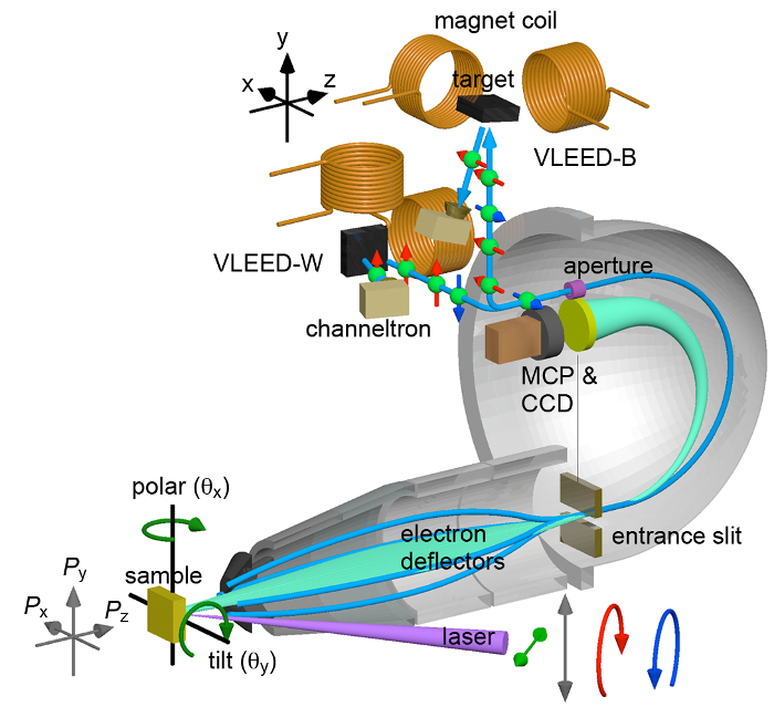
For SARPES measurement, the photoelectrons with a specific emission angle and kinetic energy analyzed by the electron analyzer are guided to two VLEED-type spin detectors with a 90-degree photoelectron deflector and the photoelectron beams are focused onto two different targets of Fe(001)-p(1×1) films terminated by oxygen. The photoelectrons reflected by the targets are detected in single channel detection by using a channeltron placed in each spin detector. The VLEED targets can be magnetized with Helmholtz-type electric coils which are arranged with orthogonal geometry with respect to each other. The magnetization direction is controlled by the bipolar condenser bank. The double VLEED spin detectors thereby enable us to analyze the spin-polarization vector of the photoelectron in three dimensions.
Protocol
1. Sample Mount and Installation
Cut single-crystal samples of Bi2Se313 in an approximate size of 1 × 1 × 0.5 mm3 and use sliver-based epoxy to glue the sample to the sample holder.
Paste the scotch tape on the sample surface. NOTE: The scotch tape is used to cleave the sample in ultrahigh vacuum (UHV) chamber to obtain an atomically clean surface.
Install the sample into the sample magazine in the load lock, and start the pump until the pressure of the load lock is lower than 1×10⁻⁵ Pa.
2. Sample Cleaving
Open the UHV valve between the load lock and the UHV preparation chamber.
Move the sample magazine from the load rock to the preparation chamber by using the linear/rotary feedthrough which is attached to the load lock chamber.
Pick up the sample from the sample magazine by the transfer rod attached to the preparation chamber.
Put back the sample magazine into the load lock and close the UHV valve.
Wait until the pressure of the preparation chamber is below 5×10⁻⁷ Pa.
Peel the scotch tape by using wobble stick in the preparation chamber and cleave the sample under the UHV condition.
3. Sample Transfer to The Measurement Position
Transfer the sample to the UHV measurement chamber, and fix the sample to the main gonio-stage by the screw driver equipped with the measurement chamber.
Move the gonio-stage to the measurement position and use the micrometer stage to precisely move the sample position onto the focus of the spectrometer.
4. 7eV-laser Setup
Turn on the Nd:YVO4 laser. NOTE: The laser generates 355 nm laser light with a high repetition rate of 120 MHz.
Open the laser beam shutter, and make sure that the laser passes through the KBBF crystal and a second-harmonic wave of 177 nm (6.994 eV) is generated.
Optimize the power of the 7eV-laser by changing the power of the 355-nm laser with the variable attenuator.
5. ARPES Data Acquisition
Open the analyzer control software on the desktop computer. NOTE: We use "SES software" which is a general program for controlling ScientaOmicron analyzer with an electron deflector.
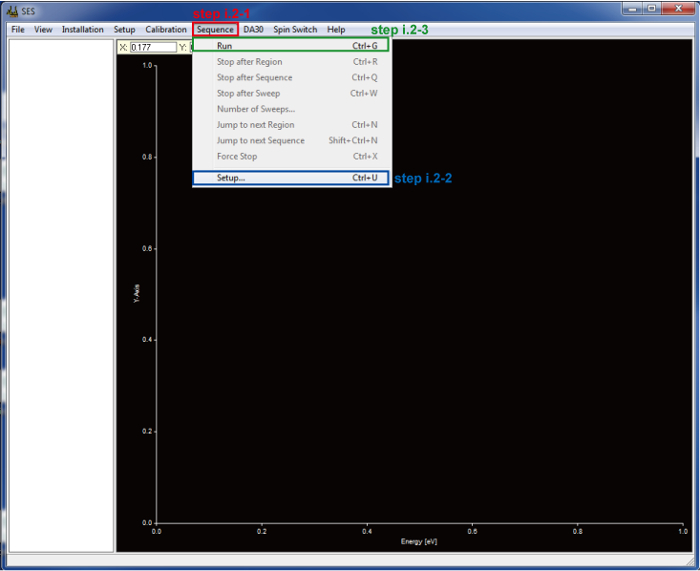
Select Setup… below Sequence on the menu bar (Figure 2, step i.2-1).
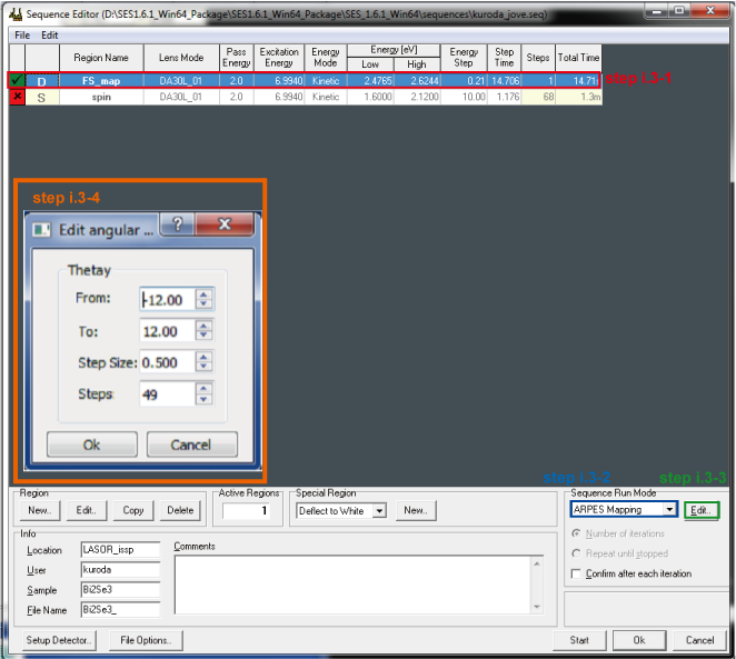
Choose ARPES configuration (Figure 3, step i.3-1) and ARPES Mapping in the list (Figure 3, step i.3-2) to perform Fermi surface mapping with the photoelectron deflector.
Click Edit (Figure 3, step i.3-3) and configure Fermi surface mapping ranging from -12° to 12° of an emission angle θy with step size of 0.5° (Figure 3, step i.3-4). NOTE: The hemispherical analyzer with an electron deflector enables us to map the Fermi surface without the sample rotations.
Click Run (Figure 2, step i.2-3).
6. SARPES Data Acquisition
Manually change the machine set-up for SARPES measurement including the analyzer entrance slit and the aperture size (Figure 1).
Select Setup… below Sequence on the menu bar (Figure 2, step i.2-2).
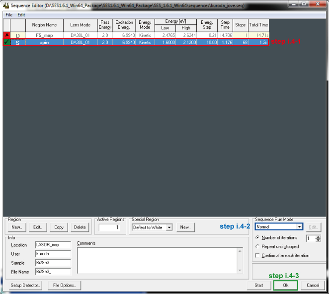
Choose Spin configuration (Figure 4, step i.4-1) and Normal in the list (Figure 4, step i.4-2), and click OK (Figure 4, step i.4-3).
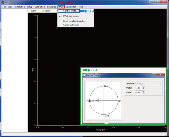
Select DA30 (Figure 5, step i.5-1) on the menu bar and Control Theta… (Figure 5, step i.5-2) to open the setting panel for the DA30 angle (θx, θy) configuration.
Choose the emission angle (θx, θy) = (-6°, 0°) to take SARPES spectra (Figure 5, step i.5-3).
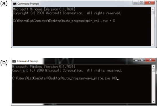
Apply magnetic field by controlling the bipolar condenser bank to magnetize the VLEED target in positive direction along the particular axis (α: x, y, or z). NOTE: In our system, this process can be done through command prompt [Figure 6 (a)].
Click Run to take intensity spectrum (Figure 2, step i.2-3).
Apply magnetic field to magnetize the VLEED target in negative direction along α and start scan to take intensity spectrum.
Calculate the spin-polarization and the spin-resolved spectra.
7. Scanning the light polarization dependence
Change the angle of the λ/2-waveplate precisely controlled by the stepping motor to tune the light polarization of the 7 eV-laser. NOTE: In our system, this process can be done through command prompt [Figure 6 (b)].
Take the spin-resolved spectra for x, y and z axes.
Scan the spin-resolved spectra as a function of the light polarization with varying the half waveplate angle from 0° to 102° with step size of 3°.
Representative Results
Before starting SARPES experiments, k positions need to be accurately determined for taking spin-resolved spectrum by using high statistic spin-integrated ARPES results with high energy- and angular-resolutions (protocol 5.1-5.5). This is demonstrated in Figure 7 where the ARPES results for a Bi2Se3 single crystal are presented. This material is known as a prototypical topological insulator with a spin-polarized surface states14,15. The ARPES band map clearly resolves the very steep Dirac-cone-like energy dispersion of the two-dimensional surface state16. The ARPES results confirm high quality of the cleaved surface and the sample orientation. From the energy and momentum information of the band map and the Fermi surface mapping, one can now choose the specific emission angle for SARPES experiment.
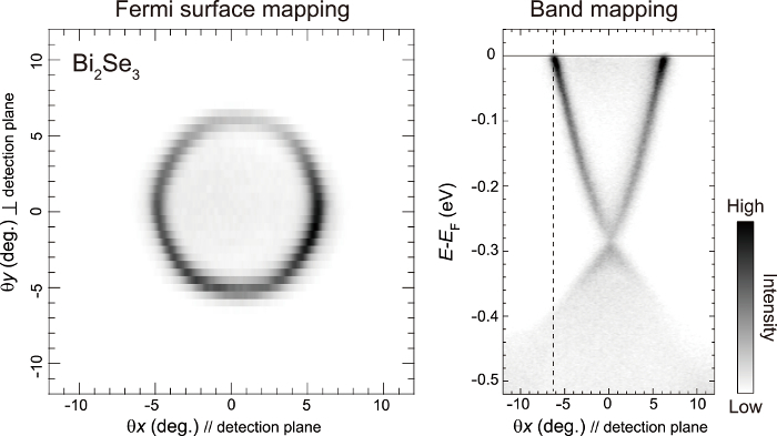
Figure 8(a) represents the energy distribution curves (EDCs) for different magnetization direction (+My and -My) taken at (θx, θy)=(-6°, 0°) across -kF of the surface band, corresponding to the cut along the dashed line shown in Figure 7. From the data, the spin-resolved EDCs can be obtained in the following. At first, the spin polarization (Py) is estimated by using this relation:


where α is the resolved axis (x, y and z), and I+M α (I-M α) is the photoelectron intensity for +M α (-M α), and Seff is the Sherman function which is typically 0.311. The obtained Py curve is shown in Figure 8 (b). The spin-resolved spectra for spin-up (![]() ) and spin-down (
) and spin-down (![]() ) are then obtained by:
) are then obtained by:

The resulting spin-resolved spectra are shown inFigure 8(c).
The double VLEED spin detectors allow us to obtain 3D spin-resolution along x, y and z axes. This is demonstrated in Figure 9(a) where the spin-resolved spectra by using p-polarization set-up and the corresponding spin-polarization (Px, Py and Pz) are shown. The clear peak near the Fermi energy is assigned to the surface state of Bi2Se3. The data represents that Py is fully spin-polarized ~100 % while the other components, Px and Pz, are negligibly small. The 3D spin-resolved spectra thus illustrate the spin quantum axis of the surface state fixed along y, which is consistent with band calculations16,17,18.
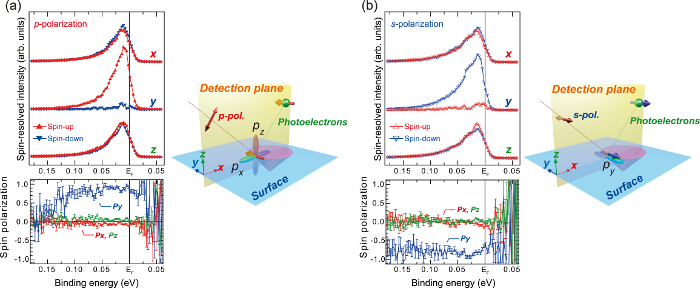
Then, we focus on the orbital selective excitation of p- and s-polarized laser. In general, under strong spin-orbit coupling, different orbital symmetry is mixed with opposite spinor in a single eigenfunction17,18. In our experimental geometry, p-polarized (s-polarized) light is sensitive to px and pz (py) orbital components in the spin-orbit coupled wavefunction (inset in Figure 9). Thereby, through the spin-orbital coupling, orbital-selective laser-SARPES should detect opposite spin-polarization for p- and s-polarization. Indeed, this is demonstrated in Figure 9(a) and 9(b). We clearly observe significant light polarization dependence of Py directly displaying spin-orbit coupling effect in the surface state17,18.
In addition, laser-SARPES affords to further investigate the linear-polarization evolution of Px, Py and Pz even with tilted light polarization between p- and s-polarizations19. As shown in Figure 10(a), laser-SARPES with 3D spin detection displays Px, Py and Pz at 0.025 eV of the binding energy as a function of the linear-polarizations. Here, the result contains 102 data points, which was acquired within 6 h. The polarization dependence of Py is easily explained by a fact that the positive and negative Py of the photoelectrons excited by p- and s-components of the applied laser cancel out. However, this cannot explain the evolution of Px and Pz. To completely describe this result, it is necessary to consider coherent spin process in photoemission as summarized in Figure 10(b). If the linear polarization simultaneously excites spin-up and spin-down states, these two quantum-spin bases are coherently superposed in a photoelectron state, resulting in the spin rotation. In fact, the displayed polarization dependence is well reproduced by the model calculation with a consideration of coherent interference between spin-up and spin-down excited by p- and s-polarizations19. The similar spin effect has been alternatively observed by 3D SARPES with synchrotron radiation20,21.
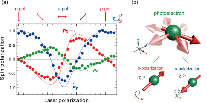
Figure 1: Schematic drawing of the detection systems of laser-SARPES. Two VLEED spin-detectors arranged with orthogonal geometry are connected to the hemispherical photoelectron analyzer. This figure has been modified from Yaji, K. et al.11. Please click here to view a larger version of this figure.
Figure 2: Screenshots of the analyzer control software. Steps i.2-1 to i.2-3 show how to start for selecting detection mode (ARPES or SARPES) and taking data. Please click here to view a larger version of this figure.
Figure 3: Screenshots of the control panel for choosing detection-mode. Steps i.3-1 to i.3-4 show how to start Fermi surface mapping. If the button Edit is pressed (step i.3-3), the new panel will pop up to define the properties of the mapping (step i.3-4).
Figure 4: Screenshots of the control panel for choosing detection-mode. Steps i.4-1 to i.4-3 show how to start SARPES mode. If the region of spin is selected (step i.4-1) and the bottom OK is pressed (step i.4-3), the panel will close and the whole analyzer setup will turn to be the SARPES mode.
Figure 5: Screenshots of the electron deflector control-panel. Steps i.5-1 to i.5-3 show how to control the photoelectron deflector. If the region control theta… is pressed (step i.5-2), the new panel will pop up to define the properties of the photoelectron deflector (step i.5-3). Please click here to view a larger version of this figure.
Figure 6: Screenshots of the panels for magnetic field of spin targets and light polarization. These properties are controlled by command lines in our system. (a) the command to control the magnetic field for spin targets: "spin_coil.exe + X" corresponds to "the name of the application file", "the direction of the field, + or -" and "the axis, x, y or z". (B) the command to control the light polarization: "wave_plate.exe 180" corresponds to "the name of the application file" and "the angle of the λ/2-waveplate".
Figure 7: Fermi surface mapping and E-k band mapping of Bi2Se3 surface state by using ARPES. The dash line indicates k position for taking spin-resolved spectra shown in Figure 8 and Figure 9. Please click here to view a larger version of this figure.
Figure 8: Spin- and angle-resolved surface band spectra of Bi2Se3. (a) Energy distribution curves (EDCs) measured for different magnetization directions +My and -My at a fixed emission angle corresponding to the dashed line cut in Figure 7. (b) Spin polarizations as a function of binding energy obtained from the spin-resolved analysis. (c) The resulting EDCs for spin-up (red triangles) and spin-down (blue triangles) channels. Please click here to view a larger version of this figure.
Figure 9: p- and s-polarization dependence of photoelectron spin from the surface state of Bi2Se3. (a) and (b) 3D spin-resolved spectra forx, y and z axes, and the corresponding spin polarizations (Px, Py and Pz) as a function of binding energy obtained by p- and s-polarizations at a fixed emission angle corresponding to the dashed line cut in Figure 7. In the inset, experimental configurations for p- and s-polarizations are shown. This figure has been modified from Kuroda K. et al.19. The p- (s-) polarization selectively excites px and pz (py) like orbital wavefunction. The px and pz (py) states are coupled to +y spin (−y spin) in the spin-orbital coupled surface state16,17. Please click here to view a larger version of this figure.
Figure 10: Three-dimensional spin polarization effect induced by linearly polarized light. (a)The plots of Px,y,z of the Bi2Se3 surface state with respect to the applied linearly polarized laser. In the inset, the applied electric field of the laser projected onto the x-z plane is shown. The overall data points were taken within 6 h. This figure has been modified from Kuroda, K. et al.19. (b) Visualized 3D spin rotation due to the interference of spin-up and spin-down spin. Please click here to view a larger version of this figure.
Discussion
ARPES and SARPES techniques have been commonly used for studying electronic band structures through the band mapping and spin-detection1,2. In addition to these general advantages shown above, laser-SARPES based on orbital selection rule in optical dipole excitation can be employed as a novel technique for visualizing the spin-orbital coupling effect in the wavefunction and quantum spin interference. As demonstrated in Figure 9 and 10, the polarization of laser can be easily manipulated just by waveplates to tilted linear polarizations between p- and s-polarizations19. In principle, circular and even elliptical polarized lights can be obtained and used in laser-SAPRES. This variety of tunable polarization is hardly obtained in conventional light source such as noble-gas-discharge lamp and synchrotron radiation. Therefore, a combination of polarization-variable laser and SARPES with 3D spin-resolution dramatically increases a capability of photoemission technique.
To perform laser-SARPES under the best condition, one must be always careful about space-charge effect12, which generally broadens the energy of the photoelectrons due to Coulomb repulsion in a dense electron packet emitted by the high intensity laser. If this issue appears, one needs optimize the power of the 7-eV laser (step 4.3). Second, if the photoelectron intensity from samples is poor, the analyzer entrance slit, and the aperture should be open (step 6.1), however, the energy resolution is sacrificed in this case. Therefore, one needs carefully select the experimental set-up to fit laser-SARPES experiments.
The main disadvantage of laser-SARPES compared to standard photoemission technique with synchrotron radiation is that in laser-SAPRES the photon energy of laser is generally not tunable. In photoemission technique, the tunable photon is necessary to probe kz dispersion, and identifies 3D bulk band structures and two-dimensional surface states1. Moreover, the photon energy of 7 eV used in this paper can scan small k area compared to that with higher photon energy. Therefore, laser-SARPES is likely restricted into the investigations of two-dimensional surface states around Brillouin zone center.
However, it should be noted that the power of laser-SARPES technique can be widely applied for spin-orbit coupled states. Recently, by using the protocol described within this paper, we have further revealed strong spin-orbit coupling effect and its significant k-dependence in Bi thin film22 and BiAg2/Ag(111) surface alloy23. Also, it is worth noting that high-efficient SARPES technique is just beginning to develop and gradually becomes a standard experimental technique. The protocol is intended to help researchers use SARPES and understand the produced data.
Disclosures
The authors declare that they have no competing financial interests.
Acknowledgments
We thank M. Nakayama, S. Toyohisa, A. Fukushima and Y. Ishida for supports to the experimental setup. We gratefully acknowledge funding from the JSPS Grantin-Aid for Scientific Research (B) through Project No. 26287061 and for Young Scientists (B) through Project No. 15K17675. This work was also supported by MEXT of Japan (Innovative Area "Topological Materials Science," Grant No. 16H00979) and JSPS KAKENHI (Grant No. 16H02209)
References
- Damascelli A, Hussain Z, Shen Z-X. Angle-resolved photoemission studies of the cuprate superconductors. Rev. Mod. Phys. 2003;75(2):473–541. [Google Scholar]
- Johnson PD. Spin-polarized photoemission. Rep. Prog. Phys. 1997;60(11):1217–1304. Available from: http://iopscience.iop.org/article/10.1088/0034-4885/60/11/002/meta. [Google Scholar]
- Qiao S, Kimura A, Harasawa A, Sawada M, Chung J-G, Kakizaki A. A new compact electron spin polarimeter with a high efficiency. Rev. Sci. Instrum. 1997;68(12):4390–4395. [Google Scholar]
- Dil JH. Spin and angle resolved photoemission on non-magnetic low-dimensional systems. J. Phys. Condens. Matter. 2009;21(40):403001. doi: 10.1088/0953-8984/21/40/403001. [DOI] [PubMed] [Google Scholar]
- Hoesch M, et al. Spin-polarized Fermi surface mapping. J. Electron Spectrosc. 2002;124(2):263–279. [Google Scholar]
- Souma S, Takayama S, Sugawara K, Sato T, Takahashi T. Ultrahigh-resolution spin-resolved photoemission spectrometer with a mini Mott detector. Rev. Sci. Instrum. 2010;81(9):096101. doi: 10.1063/1.3480542. [DOI] [PubMed] [Google Scholar]
- Okuda T, Kimura A. Spin- and angle-resolved photoemission of strongly spin-orbit coupled systems. J. Phys. Soc. Jpn. 2013;82(2):021002. [Google Scholar]
- Okuda T, et al. A new spin-polarized photoemission spectrometer with very high efficiency and energy resolution. Rev. Sci. Instrum. 2008;79(12):123117. doi: 10.1063/1.3058757. [DOI] [PubMed] [Google Scholar]
- Jozwiak C, et al. A high-efficiency spin-resolved photoemission spectrometer combining time-of-flight spectroscopy with exchange-scattering polarimetry. Rev. Sci. Instrum. 2010;81(5):053904. doi: 10.1063/1.3427223. [DOI] [PubMed] [Google Scholar]
- Okuda T, et al. Efficient spin resolved spectroscopy observation machine at Hiroshima Synchrotron Radiation Center. Rev. Sci. Instrum. 2011;82(10):103302. doi: 10.1063/1.3648102. [DOI] [PubMed] [Google Scholar]
- Yaji K, et al. High-resolution three-dimensional spin- and angle-resolved photoelectron spectrometer using vacuum ultraviolet laser light. Rev. Sci. Instrum. 2016;87(5):053111. doi: 10.1063/1.4948738. [DOI] [PubMed] [Google Scholar]
- Shimojima T, Okazaki K, Shin S. Low-temperature and high-energy-resolution laser photoemission spectroscopy. J. Phys. Soc. Jpn. 2015;84(7):072001. [Google Scholar]
- Augustine S, Mathai E. Growth, morphology, and microindentation analysis of Bi2Se3, Bi1.8In0.2Se3, and Bi2Se2.8Te0.2 single crystals. Mater. Res. Bull. 2001;36(13):2251–2261. [Google Scholar]
- Hasan MZ, Kane CL. Colloquium: Topological insulators. Rev. Mod. Phys. 2010;82(4):3045–3067. [Google Scholar]
- Ando Y. Topological insulator materials. J. Phys. Soc. Jpn. 2013;82(10):102011. [Google Scholar]
- Zhang H, Liu C-X, Qi X-L, Dai X, Fang Z, Zhang S-C. Topological insulators in Bi2Se3, Bi2Te3 and Sb2Te3 with a single Dirac cone on the surface. Nature Phys. 2009;5(6):438–442. [Google Scholar]
- Cao Y, et al. Mapping the orbital wavefunction of the surface states in three-dimensional topological insulators. Nature Phys. 2013;9(8):499–504. [Google Scholar]
- Zhang H, Liu C-X, Zhang S-C. Spin-orbital texture in topological insulators. Phys. Rev. Lett. 2013;111(6):066801. doi: 10.1103/PhysRevLett.111.066801. [DOI] [PubMed] [Google Scholar]
- Kuroda K, et al. Coherent control over three-dimensional spin-polarization for the spin-orbit coupled surface state of Bi2Se3. Phys. Rev. B. 2016;94(16):165162. [Google Scholar]
- Meier F, et al. Interference of spin states in photoemission from Sb/Ag(111) surface alloys. J Phys-Condens Mat. 2011;23(7):072207. doi: 10.1088/0953-8984/23/7/072207. URL: http://iopscience.iop.org/article/10.1088/0953-8984/23/7/072207/meta. [DOI] [PubMed] [Google Scholar]
- Dil JH, Meier F, Osterwalder J. Rashba-type spin splitting and spin interference of the Cu(111) surface state at room temperature. J Electron Spectrosc. 2015;201:42–46. [Google Scholar]
- Yaji K, et al. Spin-dependent quantum interference in photoemission process from spin-orbit coupled states. Nature Commun. 2017;8:14588. doi: 10.1038/ncomms14588. [DOI] [PMC free article] [PubMed] [Google Scholar]
- Noguchi R, et al. Direct mapping of spin and orbital entangled wave functions under interband spin-orbit coupling of giant Rashba spin-split surface states. Phys. Rev. B. 2017;95(6):04111(R). [Google Scholar]


