Abstract
Microfluidic droplet sorting allows selection of subpopulations of cells, nucleic acids, and biomolecules with soluble assays. Dielectrophoresis is widely used for sorting because it generates strong forces on droplets, actuates rapidly, and is easy to integrate into microfluidic chips. However, existing device designs apply a short force, limiting the deflection of droplets and, therefore, the speed and reliability of sorting. We describe a concentric design that applies a long force, allowing large deflections and increased reliability. We demonstrate the utility of this design by sorting polydispersed emulsions, which are typically difficult to sort with high purity.
Graphical Abstract
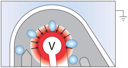
Concentric electrodes generate a uniform dielectrophoretic force that enhances droplet sorting reliability.
Droplet microfluidics enables high-throughput generation of discrete, aqueous reactors with numerous applications in chemistry and biology 1–3. Microfluidic devices perform requisite operations – generation, reagent addition, sorting – on droplets. Sorting is particularly important when a target must be recovered from a heterogeneous mixture, including for the isolation of immune cells secreting specific antibodies 4, engineered yeast producing desired small molecule products 5, and cancer cells containing specific mutations 6.
Droplet sorting can be accomplished using pneumatic, magnetic, thermal, acoustic, and electric methods 7, each varying in speed, reliability, and ease of implementation. Pneumatic valves physically deform microchannels to divert droplets, but are limited to hundred-hertz sorting by channel pressurization time 8. Magnetic approaches are even slower and require incorporation of magnetic particles in the droplets 9. Surface acoustic waves achieve kilohertz sorting, but require multicomponent devices comprised of flow channels and carefully aligned piezoelectrics 10,11. Dielectrophoretic (DEP) designs 12 are simple, monolithic devices in which precision electrodes are easily integrated by filling flow channels with solder or saltwater 13; moreover, they can achieve 30 kilohertz droplet sorting 14.
DEP sorting speed and robustness depends on device design. Recent advances increase drop periodicity, bias negative droplets to a waste channel, and prevent drop splitting at the sorter exit junction 14. This is accomplished with a two-layer design. Re-injected droplets are pancaked in the first layer, which ensures that they enter single file and are spaced evenly. Periodic drops are then biased toward the waste with oil from a parallel channel. A first-layer gapped-divider pins drops to the far wall during bias oil addition. A similar gapped-divider at the exit prevents drops from breaking by deflecting them beneath the divider. In this design, sorting accuracy is limited by the maximum droplet displacement achieved by the electrode. Displacement distance depends on the magnitude and time over which the DEP force acts. Faster droplets displace less because they pass quickly through the electric field. Voltage can be increased to compensate, but at high voltages dielectric breakdown destroys the device, tears flowing droplets, and coalesces the injected emulsion 14. With this limitation, faster, more reliable sorting requires methods that increase the time over which the DEP force acts.
We describe a new sorting geometry that uses concentric electrodes to increase the time over which the DEP force acts and, thus, the displacements that can be achieved at equivalent speed and voltage conditions. Larger displacements provide flexibility in tuning bias and spacer flow rates, improving rejection of false positives and tolerance to polydispersity.
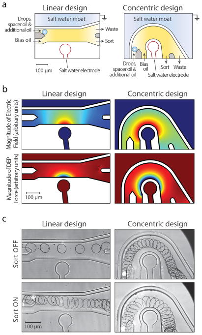
During DEP sorting, the force applied to a droplet depends on the shape of the electric field through which it passes. Typical geometries use a straight channel with the sort electrode positioned at a point down its length (Fig 1A, left) 15–18. This produces weak DEP forces up- and down-stream, but strong ones directly opposite the electrode (Fig 1B). Most of the drop deflection occurs over the short time the droplet is directly in front of the electrode. Since DEP depends on the electric field gradient, increasing the size of the electrode reduces the DEP force magnitude in the x-y plane for the majority of the electrode’s length. By contrast, a curved electrode can produce a sustained, high-magnitude force throughout the sort channel.
Fig. 1.
Design and modeling of the dielectrophoretic droplet sorters. A) Schematic of the linear and concentric design with inlet and outlet channels labeled. Gray areas represent oil bypass regions generated by double-layer fabrication. B) Modeling the Electric field and DEP force within channels C) Visualization of droplets with and without an applied voltage (700V linear, 500V concentric).
By curving the flow channel around the curved electrode, we increase the time the droplet is in the high-force region without reducing force magnitude, yielding larger displacements for similar voltage and flow conditions (Fig 1A, right). We model the electric field (Fig 1B, top) and DEP force (Fig 1B, bottom) of the linear (left) and concentric (right) designs. The time-independent numerical simulation is performed with COMSOL Multiphysics software using the Electrostatics module. Both the linear and concentric devices are divided into four domains: electrode, flow channel, grounded-moat, and polydimethylsiloxane walls. Dielectric constants are prescribed according to the material within the domain. No surface charges are assumed at the interface between domains. Applying 700 Volts to the electrode domain and 0 Volts to the moat domain generates the electric field.
Simulations show that the concentric geometry flows droplets through the high-force region over a longer distance than the linear geometry (Fig 1B, bottom); this yields larger deflections for equivalent conditions, as we empirically confirm (Fig 1C). To quantify performance differences, we track droplet trajectories for different oil flow rates and voltages using a published droplet morphometry and velocimetry tool 19. The concentric design allows higher oil flow rates (Fig 2A) and requires lower voltages (Fig 2B) to deflect drops into the collection channel. For these experiments, devices are fabricated as previously described 14 with 2M NaCl saltwater electrodes. The first layer is 30 μm and the second layer is 65 μm. Droplets are generated on a flow-focus device upstream of the sorter with 100 μl/hr aqueous solution (0.1% Tween in PBS) and 2500 μl/hr fluorinated oil (3 M, HFE-7500) with 2% surfactant 20. To sort, a rectangular square wave (20 pulses, 80 μs pulse width) amplified 1,000-fold by a high voltage amplifier (Trek 609E-6) is applied to the electrode.
Fig. 2.
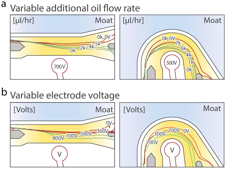
Drops are deflected more in the concentric design. Drop trajectories as a function of (A) additional oil flow rates (μl/hr), and (B) electrode voltages (V). Red represents a failed sort trajectory.
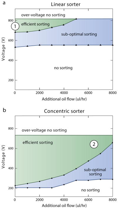
To characterize the voltages and speeds for which efficient sorting occurs in both designs, we again generate droplets on-chip. Additional oil is added to adjust speed without changing drop formation. The bias oil flow rate is set to be the sum of the aqueous flow rate (100 μl/hr), drop-maker oil flow rate (2500 μl/hr oil), and additional oil flow rate (variable). At incrementally increasing additional oil flow rates, the voltage of the electrode is scanned to determine 1) the voltage at which sorting begins, 2) the voltage at which sorting is 100%, and 3) the voltage at which drops begin to break apart. These points define the operation window of the device. As shown in Fig 3, the concentric design efficiently sorts with a significantly larger range of voltage and flow rate combinations, including at low voltages (250 V) and high additional oil flow rates (8000 μl/hr). Sorting at low voltages is important for unstable emulsions, or in cases where the re-injected emulsion is in close proximity to the electrode.
Fig. 3.
The concentric design allows reliable sorting over a wider range of parameters. Voltage-flow windows for efficient sorting using the A) linear and B) concentric designs. Numbers (1) and (2) show the parameters used for sorting polydisperse emulsions in Figure 5.
Although microfluidics can form monodispersed droplets, handling invariably coalesces some of the emulsion, resulting in polydispersity. This is especially true for workflows requiring droplet injection into microfluidic devices. Thus, an effective sorter must tolerate polydispersity. With the linear design, we observe two major failure modes when sorting polydispersed emulsions. The first results from small droplets catching up to large ones due to their higher velocity 21. When the large droplet enters the waste channel, it alters the streamlines in the sorting junction, causing the small droplet to enter the collection channel, which results in false-positive sorting (Fig 4A). The second failure mode results from large droplets not being fully biased into the waste channel, occasionally choosing the collection channel even when the DEP field is not activated, and again yielding false positive sorting (Fig 4B).
Fig. 4.
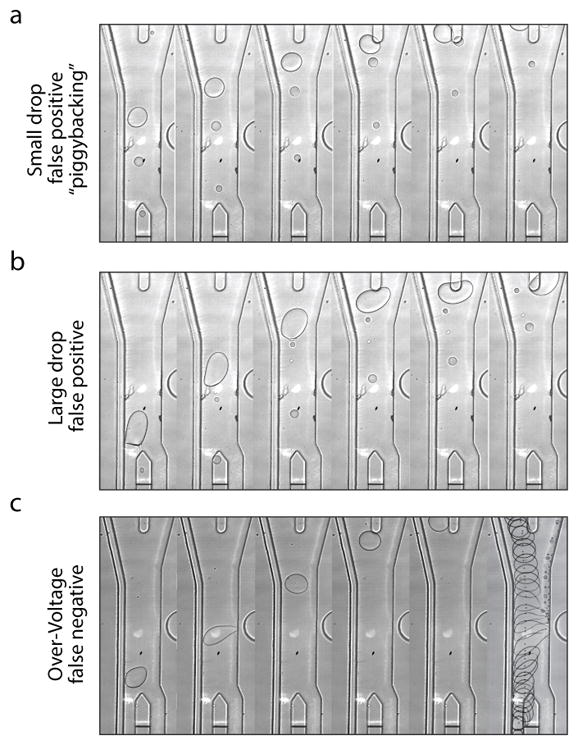
Common failure modes of droplet sorting. A) Drop size differences result in small drops catching larger ones and deflecting into the sort channel. B) Large drops following center streamlines are easily deflected into the sort channel when they contact the barrier between outlets. C) High voltage fails to sort drops, and can shear off microdroplets.
Increasing droplet spacing and bias-to-waste can mitigate both failures. However, more spacer oil increases droplet velocity, shortening DEP force duration, while a higher bias flow rate pushes droplets farther from the electrode, requiring larger displacements for collection. Compensating by increasing voltage tears droplets apart and results in incorrect sorting (Fig 4C). These issues limit the speed and polydispersity tolerance of linear sorters.
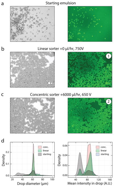
The larger operational range of our sorter affords greater flexibility in tuning spacer and bias flow rates to reject false positives, increasing tolerance to polydispersity. To demonstrate this, we compare the linear and concentric designs for sorting poly-dispersed emulsions. We generate monodispersed fluorescent droplets with a flow focus device (60 μm, 0.2μM FAM-labeled oligonucleotides) and spike them into non-fluorescent polydispersed droplets generated by vortexing (0.1% Tween-20, 30s hand vortexing), generating a polydispersed emulsion (Fig 5A). We sort the emulsion with both devices and compare the purity of the sorted drops. While the linear design can recover most of the positives, a substantial number of false positive, non-fluorescent droplets are also recovered (Fig 5B). This can be problematic for biological applications, like single-cell sequencing, that are sensitive to contaminating material. By contrast, the concentric device efficiently sorts positives from the polydispersed emulsion with low false positive rates, as demonstrated by fluorescence microscopy (Fig 5C) and image analysis of sorted drop sizes and intensities (Fig 5D).
Fig. 5.
The concentric design allows more reliable sorting of polydisperse emulsions. Images show brightfield and GFP-channel data from the A) starting emulsion, and drops sorted using the B) linear and C) concentric sorters. D) Density plots of drop size and fluorescence intensity of drops pre- and post-sort.
Conclusion
We have developed a concentric droplet sorter that achieves larger displacements than linear designs for similar voltage and flow conditions. This provides flexibility in tuning parameters to efficiently reject false positives, making the design tolerant to polydispersity. Since polydispersity is an unavoidable consequence of microfluidic workflows but can confound results, sorters able to tolerate non-uniform drop sizes are valuable. Moreover, our design retains features that make DEP advantageous for droplet sorting, including high speed and use of simple-to-fabricate monolithic chips.
Footnotes
Conflict of interest
There are no conflicts to declare.
References
- 1.Guo MT, Rotem A, Heyman JA, Weitz DA. Lab Chip. 2012;12:2146–2155. doi: 10.1039/c2lc21147e. [DOI] [PubMed] [Google Scholar]
- 2.Prakadan SM, Shalek AK, Weitz DA. Nature Reviews Genetics. 2017;18 doi: 10.1038/nrg.2017.15. nrg.2017.15–361. [DOI] [PMC free article] [PubMed] [Google Scholar]
- 3.Kintses B, van Vliet LD, Devenish SR. Current Opinion in Chemical Biology. 2010;14:548–555. doi: 10.1016/j.cbpa.2010.08.013. [DOI] [PubMed] [Google Scholar]
- 4.Mazutis L, Gilbert J, Ung WL, Weitz DA, Griffiths AD, Heyman JA. Nature Protocols. 2013;8:870–891. doi: 10.1038/nprot.2013.046. [DOI] [PMC free article] [PubMed] [Google Scholar]
- 5.Abatemarco J, Sarhan MF, Wagner JM, Lin JL, Liu L, Hassouneh W, Yuan SF, Alper HS, Abate AR. Nat Comms. 2017;8:332. doi: 10.1038/s41467-017-00425-7. [DOI] [PMC free article] [PubMed] [Google Scholar]
- 6.Pellegrino M, Sciambi A, Yates JL, Mast JD, Silver C, Eastburn DJ. BMC Genomics. 2016;17:361. doi: 10.1186/s12864-016-2694-2. [DOI] [PMC free article] [PubMed] [Google Scholar]
- 7.Xi HD, Zheng H, Guo W, Gañán-Calvo AM, Ai Y, Tsao CW, Zhou J, Li W, Huang Y, Nguyen NT, Tan SH. Lab Chip. 2017;17:751–771. doi: 10.1039/c6lc01435f. [DOI] [PubMed] [Google Scholar]
- 8.Cao Z, Chen F, Bao N, He H, Xu P, Jana S, Jung S, Lian H, Lu C. Lab Chip. 2013;13:171–178. doi: 10.1039/c2lc40950j. [DOI] [PubMed] [Google Scholar]
- 9.Zhang K, Liang Q, Ma S, Mu X, Hu P, Wang Y, Luo G. Lab Chip. 2009;9:2992–8. doi: 10.1039/b906229g. [DOI] [PubMed] [Google Scholar]
- 10.Franke T, Braunmüller S, Schmid L, Wixforth A, Weitz DA. Lab Chip. 2010;10:789–794. doi: 10.1039/b915522h. [DOI] [PubMed] [Google Scholar]
- 11.Franke T, Abate AR, Weitz DA, Wixforth A. Lab Chip. 2009;9:2625–2627. doi: 10.1039/b906819h. [DOI] [PubMed] [Google Scholar]
- 12.Ahn K, Kerbage C, Hunt TP, Westervelt RM, Link DR, Weitz DA. Applied Physics Letters. 2006;88:024104–3. [Google Scholar]
- 13.Sciambi A, Abate AR. Lab Chip. 2014;14:2605–2609. doi: 10.1039/c4lc00078a. [DOI] [PMC free article] [PubMed] [Google Scholar]
- 14.Sciambi A, Abate AR. Lab Chip. 2015;15:47–51. doi: 10.1039/c4lc01194e. [DOI] [PMC free article] [PubMed] [Google Scholar]
- 15.Baret J-C, Miller OJ, Taly V, Ryckelynck M, El Harrak A, Frenz L, Rick C, Samuels ML, Hutchison JB, Agresti JJ, Link DR, Weitz DA, Griffiths AD. Lab Chip. 2009;9:1850–10. doi: 10.1039/b902504a. [DOI] [PubMed] [Google Scholar]
- 16.Agresti JJ, Antipov E, Abate AR, Ahn K, Rowat AC, Baret JC, Marquez M, Klibanov AM, Griffiths AD, Weitz DA. PNAS. 2010;107:4004–4009. doi: 10.1073/pnas.0910781107. [DOI] [PMC free article] [PubMed] [Google Scholar]
- 17.Beneyton T, Coldren F, Baret JC, Griffiths AD, Taly V. Analyst. 2014;139:3314–3323. doi: 10.1039/c4an00228h. [DOI] [PubMed] [Google Scholar]
- 18.El Debs B, Utharala R, Balyasnikova IV, Griffiths AD, Merten CA. PNAS. 2012;109:11570–11575. doi: 10.1073/pnas.1204514109. [DOI] [PMC free article] [PubMed] [Google Scholar]
- 19.Basu AS. Lab Chip. 2013;13:1892–1901. doi: 10.1039/c3lc50074h. [DOI] [PubMed] [Google Scholar]
- 20.Holtze C, Rowat AC, Agresti JJ, Hutchison JB, Angilè FE, Schmitz CHJ, Köster S, Duan H, Humphry KJ, Scanga RA, Johnson JS, Pisignano D, Weitz DA. Lab Chip. 2008;8:1632–1639. doi: 10.1039/b806706f. [DOI] [PubMed] [Google Scholar]
- 21.Ahn K, Agresti J, Chong H, Marquez M, Weitz DA. Applied Physics Letters. 2006;88:264105. [Google Scholar]


