Abstract
Human gait involves a repetitive cycle of movements, and the phase of gait represents the location in this cycle. Gait phase is measured across many areas of study (e.g., for analyzing gait and controlling powered lower-limb prosthetic and orthotic devices). Current gait phase detection methods measure discrete gait events (e.g., heel strike, flat foot, toe off, etc.) by placing multiple sensors on the subject’s lower-limbs. Using multiple sensors can create difficulty in experimental setup and real-time data processing. In addition, detecting only discrete events during the gait cycle limits the amount of information available during locomotion. In this paper we propose a real-time and continuous measurement of gait phase parameterized by a mechanical variable (i.e., phase variable) from a single sensor measuring the human thigh motion. Human subject experiments demonstrate the ability of the phase variable to accurately parameterize gait progression for different walking/running speeds (1 to 9 miles/hour). Our results show that this real-time method can also estimate gait speed from the same sensor.
I. INTRODUCTION
Human gait analysis involves studying joint kinematics and kinetics during locomotion. Analyzing the joint kinematics has widely been used to prescribe treatments for patients during physical therapy or rehabilitation [1]–[3] as well as to design controllers for powered prostheses [4]–[6] and orthoses [7]–[9]. Gait study data is typically captured from large, expensive equipment including a motion capture system and force plates [2]. Recent gait analysis methods have shifted from using large conventional equipment to using small sensors placed on the human body limbs and joints, known as wearable sensors [10]–[12]. Wearable sensors have shown promise for assessing human movement, where gait analysis can be performed in both research and clinical applications.
Human gait involves a repetitive cycle of movements, and the phase of gait represents the location in this cycle. Gait phases are typically viewed as discrete events through the gait cycle (i.e., heel strike, midstance, etc.), where each phase are classified as percentage intervals of the gait cycle (0% to 100%). Gait phase detection using wearable sensors provides a low cost solution without requiring large lab space, and allows clinicians to perform tests outside the research environment to monitor subjects for long periods of time. Generally, wearable sensors consist of accelerometers, gyroscopes, magnetometers, and force sensors to create a collective system for determining phases in gait. However, using multiple sensors can become a challenge as each sensor can require its own calibration and adjustments, which can entail additional setup time before and during experiments. Thus, the challenge in using wearable sensors for gait analysis lies in developing a real-time, algorithm-based system that is robust and portable for a clinical environment.
Several algorithms to detect gait phases have been developed using wearable sensors. Some of these algorithms use gait classifiers to detect several discrete events occurring over a gait cycle (e.g., heel strike, toe off, etc.) [3]. Rule-based algorithm methods for defining gait classifiers have been implemented using a wearable three-axis inertial measurement unit (IMU) sensor attached to both shanks [13] or the thigh, shank, and foot [14]. Other discrete gait phase detection algorithms try to reduce classification errors by introducing more sensors, such as using force sensitive resistors (FSRs) under the shoe insole to measure ground contact forces [15]–[17]. Detection issues can arise from using FSRs under the shoe insole since shear forces can lead to faulty measurements and damage of the sensors, thus requiring frequent replacement.
Classifier methods detect phases discretely, which neglects the continuous behavior of human walking within these discrete phases. Human subject experiments using a motion capture system (Vicon, Oxford, UK) have demonstrated that the thigh motion can uniquely represent the gait cycle continuously [18]. The study demonstrated that the phase angle from the thigh phase portrait (angular position vs. velocity) can indicate the subject’s progression along the gait cycle even during non-steady walking. The thigh phase angle provides a human-inspired phase variable: a time-invariant, kinematic quantity capturing the forward (or backward) locomotion during stride. Previous work in [19] identified gait phases continuously using multiple FSRs under a custom shoe insole, but do not measure gait phases in a unified, continuous measurement for the entire gait cycle. Other work has measured gait phase continuously across the gait cycle based on measurements of the thigh, knee, and tibia angle [20]. Their multi-sensor approach fused four different gait phase detection methods to produce an offline estimate of continuous gait phase (i.e., post-processed). Our method differs by only computing the thigh phase angle using a single sensor, which can be done continuously through the entire gait cycle in real-time. Continuously measuring gait phase by way of a phase variable can be utilized in the control of powered knee-ankle prosthesis as demonstrated in [6], [21], [22]. A similar approach based on the tibia phase angle was used to control a powered ankle prosthesis through the gait cycle [23], but the tibia phase angle may not provide as robust a parameterization of the human gait cycle as the thigh phase angle [18].
This paper proposes a real-time method using a single IMU sensor to measure the continuous phase variable that was originally proposed in the offline analysis of [18]. Signal processing algorithms are defined to estimate a monotonic, increasing phase variable that represents the progression from 0% to 100% of the gait cycle. Our results demonstrate appropriate changes in the rate of the phase variable and the ability to predict the stance-to-swing transition across multiple walking and running speeds (1-9 miles/hour). Moreover, the polar radius from the orbit within the thigh phase portrait provides a linear relationship for estimating the subject’s walking speed during gait.
II. Real-Time Estimation Methods
A. Continuous Gait Phase Variable
The continuous phase variable is constructed by the phase angle from the thigh phase portrait (i.e., phase plane of thigh velocity vs. angle). The raw thigh angle is measured from an IMU sensor (LORD MicroStrain, 3DM-GX4-25) mounted to a leg holster that is strapped to the thigh along the sagittal plane (see Fig. 1). The IMU sensor has a compact size of 36 mm × 36.6 mm × 11.1 mm and weighs 16.5 g. The sensor measures its own Euler angles sampled at 500 Hz.
Fig. 1.
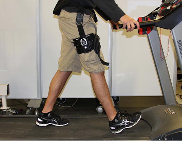
Photo of human subject walking on a treadmill while wearing an IMU sensor on the thigh with a sagittal plane orientation. Thigh angle measurement follows the righthand rule.
The start of the phase angle occurs in the first quadrant of the phase portrait along the positive x-axis. The phase angle increases as it orbits a full revolution counter-clockwise in the phase portrait, completing the gait stride at the fourth quadrant returning to the x-axis. The phase angle is computed using the four-quadrant atan2(y, x) function, which is defined as the unnormalized phase variable
| (1) |
More detail on the derivation and biomechanical implications of the phase variable can be found in [18]. The variables and θx(t) are the estimated thigh velocity and thigh angle signals, respectively, for constructing the thigh phase portrait. These variables are shifted and scaled to enhance the linearity and monotonicity of the phase variable φ(t) during a gait cycle (Section II-C).
Filters are designed to provide smooth input signals for real-time calculation of the phase variable φ(t). An interpolating polynomial filter (Section II-B) filters the raw thigh angle measurement to mitigate unwanted disturbances observed from the IMU. The thigh angle and its velocity are shifted and scaled to compute the phase variable (Section II-C), which is then passed through a monotonic filter to further mitigate the effect of noise. Finally, to detect whether or not a subject is walking, a start and stop detection algorithm is implemented (Section II-D). Fig. 2 displays a schematic of the thigh phase portrait based on (θx(t), ) coordinates as the phase variable φ(t) is measured about the circular orbit during the gait cycle. The phase variable φ(t) from Eq. 1 will compute the monotonic, increasing measurement of a subject as they progress through the gait cycle.
Fig. 2.
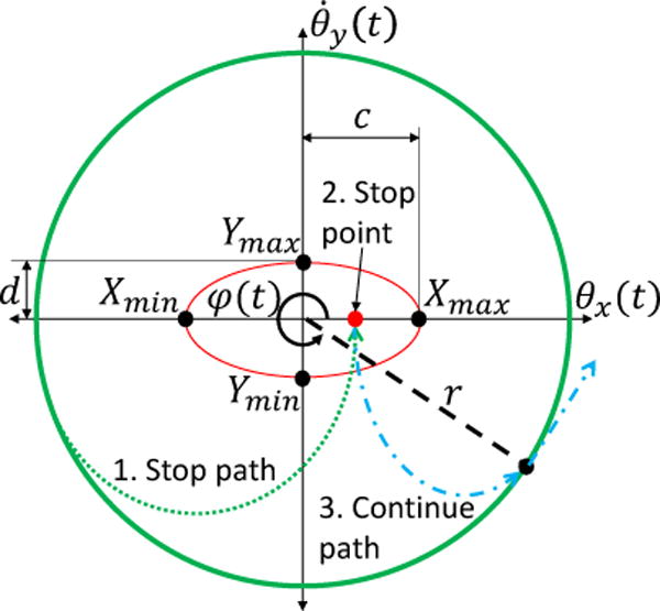
A depiction of the phase variable φ(t) measured from the circular orbit (thick green line) with a polar radius r (dashed black line) within the thigh phase portrait (θx(t), ) coordinates. The ellipse (red line) displays the predefined minimum and maximum X/Y coordinates (black dots) as well as its length of semi-axes c and d. A schematic for how start and stop detection method from Section II-D is used for a sequence of events. If a subject were to stop walking, the signal travels off the circular orbit (1. Stop path, dotted green line) to inside the ellipse (2. Stop point, red dot) near the origin. When the subject decides to continue walking then the orbital path continues (3. Continue path, dash-dot blue line) to the last recorded phase variable value to complete the stride along the circular orbit.
B. Interpolating Filter
The raw thigh angle IMU measurement can contain high frequency noise generated by impacts occurring at heel strike. Filters that help estimate joint angular position and velocity have proven to be particularly helpful in bipedal robots [24] and nonlinear control applications [25]. In the case of measuring the phase variable, the raw thigh angle can be estimated and filtered by applying a least squares method to fit an analytical function over a rolling data window [26]. This window length can be tuned in order to have minimal delay and reduce high frequency noise. Furthermore, the thigh velocity is estimated by taking the analytical derivative of the estimated thigh angle function to provide the signals in computing the thigh phase portrait. The benefits will be exploited in Section III-B showing results of the raw IMU measurement applying this filter method.
To compute the interpolating filter polynomial functions for both thigh angle and velocity from the method in [26], the raw thigh angle measurement ψ(t) is stored in a vector of size based on the chosen window length W (in samples). Each row contains a polynomial function given in the following matrix equation form:
where Δt is the time step between samples, N is the degree of the polynomial, and [a0(t), a1(t), …, aN(t)] ∊ ℝN+1 are the time-varying polynomial coefficients. Constraints are included to bias the new computed coefficients by equaling the terminal coefficients from the previous solved polynomial. This ensures continuity for consecutively generated polynomials with overlapping windows.
Solving for the unknown coefficients ai(t) for i ∊ 0, …, N by way of QR factorization [27] yields the interpolating polynomial functions
| (2) |
| (3) |
where h = (1 − η)WΔt ∈ (0, WΔt] defines the specified time within the window. The parameter η ∈ [0, 1) is a user-defined delay based on the percentage of the window length W. Eq. 2 and Eq. 3 are the estimates for thigh angle and velocity, respectively.
C. Adaptive Phase Variable Shift and Scale
The linearity of the phase variable trajectory can be improved by making the orbit in the thigh phase portrait more circular. Both θ(t) and are shifted about the origin of the thigh phase portrait, and the angle θ(t) is scaled to match the amplitude of the velocity to provide a constant orbital radius. The min/max values of the filtered angle θ(t) and velocity are stored for computing the shift and scale by evaluating
where the min/max time values correspond to the time a local extrema occurs for the thigh angle and velocity of the previous gait cycle. The minimum values are calculated over a time window starting from the previous gait cycle’s maximum, and vice versa. For example, θmax(t) is the maximum thigh angle from all samples stored in the time interval of .
The shift and scale parameters from Eq. 1 are then computed by
| (4) |
| (5) |
where z(t) is the scale parameter, and γ(t) and Γ(t) are the shift parameters calculated from the filtered thigh angle and velocity, respectively, by
The negation in ensures that the phase portrait of the thigh angle orbits in a counter-clockwise direction. This establishes an increasing and monotonic phase variable from atan2(y, x). This derivation is based on placing the IMU on the right leg. If the IMU were to be placed on the left leg, then negate only θx(t) to produce an increasing and monotonic phase variable along the gait cycle.
D. Real-Time Start and Stop Detection
If a human subject were to instantly stop walking during a stride, small disturbances from the real-time thigh angle measurements can generate false orbits on the phase portrait, resulting in unwanted signals for the phase variable φ(t). When stop walking event occurs the orbit will drive near the origin. Consequently, the phase variable will reset instead of holding the last phase variable value until the subject continues along completing the gait stride. Thus, a start and stop walking detection algorithm is implemented to handle this event, where the phase portrait coordinates (θx(t), ) are compared to an elliptical boundary centered around the phase portrait origin.
The phase portrait coordinates in Eq. 4 and Eq. 5 can be compared to a predefined ellipse
| (6) |
where (X, Y) defines the center of the ellipse, and c and d represent the length of the major and minor semi-axes, respectively. These ellipse parameters are obtained from predefined minimum and maximum X/Y coordinates {Xmin, Xmax, Ymin, Ymax} with respect to the thigh phase portrait coordinates (θx(t), ). The center of the ellipse and the semi-axes are evaluated as
Fig. 2 gives a depiction of the ellipse and its parameters within the phase portrait.
If Eq. 6 produces a value less than or equal to one, then it indicates the human has stopped walking (stop detected). Algorithm 1 applies this condition in line 2 to ultimately hold the output phase variable φf(t) (i.e., φf(t) is the output of the start/stop logic with φ(t) as the input) constant until walking resumes. To ensure continuity in φf(t) after detecting walking, line 5 clears the stopped flag when the absolute error between φf(t−Δt) and φ(t) is less than Δφ, a predefined value of acceptable discontinuity. The monotonic filter in line 9 contains two inequalities for an acceptable decrease between the current and previous φf(t) value, to allow the phase variable transition from 2π to 0 in the phase portrait at the start of a new gait cycle.
Algorithm 1.
Start and Stop Detect with Monotonic Filter
| Input: φ(t) | |
| Output: φf(t) | |
| 1: | Initialize φf(t) = φ(t), stopped = false; |
| 2: | if stop detected then |
| 3: | stopped = true; |
| 4: | else |
| 5: | if |φ(t) − φf(t − Δt)| ≤ Δφ then |
| 6: | stopped = false; |
| 7: | end if |
| 8: | end if |
| 9: | if stopped = true or then |
| 10: | φf(t) = φf(t Δt); |
| 11: | else |
| 12: | φf(t) = φ(t); |
| 13: | end if |
Normalizing the output of Algorithm 1 by φnorm(t) = φf(t)/2π, gives a unit scaled version of the phase variable corresponding to 0 to 100% of the gait cycle. The parameter φnorm(t) is considered the final normalized phase variable output for gait phase detection.
E. Gait Speed Estimate
An additional parameter within the phase portrait provides an estimate for gait cadence: the orbit’s polar radius r. From the phase portrait (θx(t), ) coordinates, the polar radius of the orbit is computed as . The polar radius has a linear correlation to the subject’s gait speed. Section III will provide experimental results for how the phase variable and cadence estimate performed across multiple speeds.
III. EXPERIMENTATION AND RESULTS
A. Experimental Protocol and Setup
The experimental protocol for testing was reviewed and approved by the Institutional Review Board (IRB) at the University of Texas at Dallas. The experiment consists of a human subject walking on a treadmill with the IMU sensor mounted to the thigh along the sagittal plane (see Fig. 1). The measured IMU sensor signals were transmitted to a dSPACE DS1007 2 GHz processor, where the phase variable algorithms from Section II were programmed in MATLAB/Simulink for real-time computing.
The testing involved a human subject initially walking on a treadmill from rest to 1 mph (miles/hour). Treadmill speed was increased by 1 mph increments in a continuous sequence up to the subject’s selected running speed (9 mph). For each speed, 45 seconds of data were recorded. The experiment ended with the subject returning back to a rest position.
B. Real-Time Thigh Angle and Velocity Results
The raw thigh angle ψ(t) measured by the IMU sensor was processed using the interpolating filter from Section II-B (Fig. 3). The raw thigh angle ψ(t) produced sharp cusps near the local maxima values, which are fully removed using the interpolated filtered thigh angle θ(t). The interpolated filtered thigh velocity removes the large impulses created from ground impacts as velocity crosses 0.0 rad/s. As a comparison, a second order (5 Hz cutoff) Butterworth low-pass filter is shown in Fig. 3. It can be seen the Butterworth filter fails to smooth out the impacts, which would result in a non-monotonic phase variable. Hence, the interpolated filter is the preferred filter method for this application. The amount of delay created by the interpolating filter is considered acceptable since it is less than the delayed reaction time from the reflex pathways of gait locomotion [28]. Applying the shift-and-scale method from Section II-C, the orbit in the thigh phase portrait becomes circular, which yields a monotonically increasing phase variable through Eq. 1.
Fig. 3.
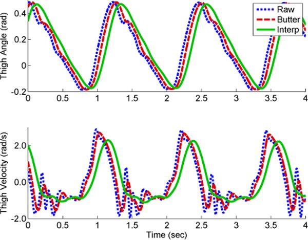
Top: the thigh angle (Raw) measured by the IMU (dotted blue line) compared against two filtered options: 1) a second order Butterworth (Butter) low-pass filter with a cutoff frequency of 5 Hz (dashed red line) and the Interpolating (Interp) filter method (solid green line). Bottom: the thigh velocity (numerically differentiated thigh angle) and the two filtered options. Signal disturbances from ground impact are observed in the thigh velocity (e.g., t ≈ 1.3 and 2.6 seconds). The Interpolating filter provides a more smooth signal than the Butterworth filter. Data is from 3 mph treadmill speed test.
C. Continuous Gait Phase Variable Across Varying Speeds
Fig. 5 shows the results of continuous, monotonic phase variables (φnorm(t)) over time across gait speeds. The shaded region represents the standard deviation, which displays a tight tolerance against the mean showing consistency in the data over consecutive strides. As expected, the slower to normal walking speeds (1-3 mph) took longer time durations to complete gait strides compared to the faster speeds. The slower speed phase variables are not perfectly linear, which is expected as the subject’s phase transitions are not uniformly paced throughout the gait cycle. The phase variable reflects the fact that each leg spends more time in stance than swing during slow to normal walking.
Fig. 5.
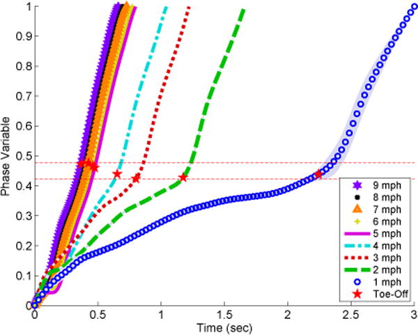
The normalized phase variable φnorm(t) vs. time across various treadmill speeds (1-9 mph) for 20 consecutive gait strides. Each phase variable curve represents the mean for that particular speed with ±1 standard deviation (shaded gray region, difficult to observe due to small variance). Toe-off is marked (red star) at the moment when the minimum thigh angle occurred. Horizontal red dashed lines give the lower and upper bounds of these events across the various speeds, demonstrating the ability of the phase variable to predict these events despite differences in timing. The slower speeds (1-3 mph) have a nonlinear phase trajectory due to a longer time duration in stance compared to swing, whereas faster speeds (≥ 4 mph) produce a linear phase trajectory due to a more even stance/swing split [2].
For the faster speeds (4-9 mph), the phase variable becomes increasingly linear as the stance and swing transition period becomes symmetrical over the gait cycle [2], [29]. Markers display the timing of toe-off (defined by the minimum thigh angle during stride), which coincides with the beginning of the swing period [3]. The slope increases from initiation of swing period (i.e., toe-off) and beyond, which indicates the subject’s transition from stance-to-swing period [2], [3]. The lower and upper lines between 0.42 and 0.47, respectively, bound the phase variable values that were observed at the stance-to-swing transition across the different speeds. The phase variable consistently predicts stance-to-swing transition within these tight bounds despite wide changes in the timing of the transition across different speeds (indicated by the x-axis of Fig. 5).
D. Gait Speed Estimator
Fig. 6 displays the phase portrait for various gait speeds. The polar radius r is distinct for each speed along the orbit. Fig. 7 displays the linear relationship of treadmill walking speed versus the polar radius (with a coefficient of determination R2 = 0.994). The least squares regression fit produces a function v(r) = 2.45r − 1.13 for estimating walking speed from polar radius. The variance of the estimate is reduced when using the mean polar radius from a single quadrant of the phase portrait (Fig. 7), where the fourth quadrant (phase angle between 3π/2 and 2π) was chosen.
Fig. 6.
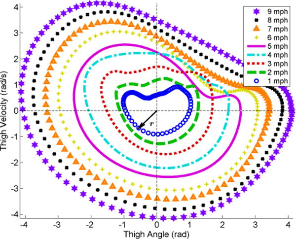
The phase portrait of vs. θx(t) across various treadmill speeds (1-9 mph) each having 20 consecutive gait strides. The polar radius r can be correlated to the subject’s gait speed. Speeds ≤ 4mph produced a circular orbit from 0 to 2π (i.e., 0% to 100% gait cycle). At 5 mph, the subject transitioned from fast walking to running, where more forceful ground impacts can be observed in the IMU measurements due to the flight phase. This produced a non-circular form after impact with intersection of other orbits at different speeds, as shown in the first quadrant for 5-6 mph.
Fig. 7.
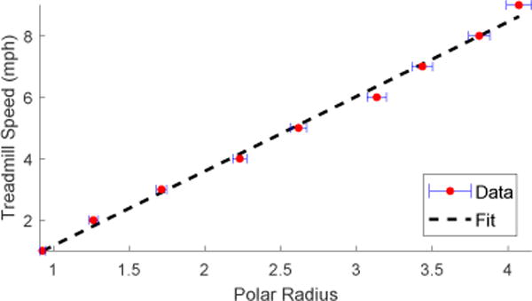
Treadmill speed vs. mean polar radius r (Data) with regression line v(r) (Fit). Note the error bars (horizontal blue lines) are ±1 standard deviation from the mean (red dots).
IV. CONCLUSIONS
This paper proposed a real-time method for continuous gait phase detection using a single wearable IMU sensor on the thigh. The relationship between the thigh angle and velocity was used to construct a phase variable that parameterizes the human gait cycle. Several algorithms were implemented that include start and stop detection and filtering methods to ensure that the phase variable is well-behaved and monotonic during a stride. Using a single sensor reduces the onboard computation and equipment needed to determine gait phase. Furthermore, this method produces an estimate of gait speed as a byproduct of the phase variable computation.
The experimental results produce a continuous measurement of gait phase that is reliable across multiple speeds. To the best of the authors knowledge, the maximum speed reached during experiments is slightly larger than the fastest speed previously reported for gait phase detection [30]. However, their method measures discrete events with multiple sensors placed along the lower limbs, whereas our approach computes the gait phases in a continuous manner from a single sensor. Our approach overcomes the limitations of discrete phase detection, estimating the continuous progression through the gait cycle. Future work will investigate the performance of the phase detection method for other ambulation modes, such as walking up slopes and stairs.
This continuous phase detection method could be used to control wearable robots in synchrony with human users. A variation of this phase variable approach has been implemented for controlling a powered knee-ankle prosthesis in a unified manner throughout the entire gait cycle for multiple subjects [31]. The phase variable also has the potential to be used for unified control of powered orthotic devices, such as exoskeletons [9].
Fig. 4.
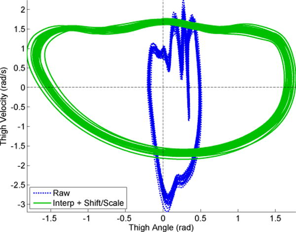
The raw thigh orbit (Raw) compared to the interpolated filtered, shifted/scaled thigh orbit (Interp + Shift/Scale) in the phase plane for 20 continuous strides at 3 mph. Applying the shift and scale algorithm produces a circular orbit shape, in contrast to the raw non-circular orbit.
Acknowledgments
This work was supported by the National Institute of Child Health & Human Development of the NIH under Award Number DP2HD080349. The content is solely the responsibility of the authors and does not necessarily represent the official views of the NIH. R. D. Gregg holds a Career Award at the Scientific Interface from the Burroughs Wellcome Fund.
Contributor Information
David Quintero, Email: dxq130330@utdallas.edu.
Robert D. Gregg, Email: rgregg@utdallas.edu.
References
- 1.Shestack R. Handbook of physical therapy. Springer; 1977. [Google Scholar]
- 2.Winter D. Biomechanics and Motor Control of Human Movement. Hoboken, New Jersey: John Wiley and Sons Inc; 2009. [Google Scholar]
- 3.Perry J, Burnfield J. Gait Analysis: Normal and Pathological function. Thorofare, New Jersey: Slack-Incorporated; 2010. [Google Scholar]
- 4.Sup F, Bohara A, Goldfarb M. Design and control of a powered transfemoral prosthesis. Int J Robot Res. 2008;27(2):263–273. doi: 10.1177/0278364907084588. [DOI] [PMC free article] [PubMed] [Google Scholar]
- 5.Simon AM, Fey NP, Finucane SB, Lipschutz RD, Hargrove LJ. IEEE Int Conf Rehab Robot. IEEE; 2013. Strategies to reduce the configuration time for a powered knee and ankle prosthesis across multiple ambulation modes; pp. 1–6. [DOI] [PubMed] [Google Scholar]
- 6.Gregg RD, Lenzi T, Hargrove LJ, Sensinger JW. Virtual constraint control of a powered prosthetic leg: From simulation to experiments with transfemoral amputees. IEEE Trans Robot. 2014;30(6):1455–1471. doi: 10.1109/TRO.2014.2361937. [DOI] [PMC free article] [PubMed] [Google Scholar]
- 7.Beil J, Perner G, Asfour T. IEEE Int Conf Rehab Robot. IEEE; 2015. Design and control of the lower limb exoskeleton kit-exo-1; pp. 119–124. [Google Scholar]
- 8.Cenciarini M, Dollar AM. IEEE Int Conf Rehab Robot. IEEE; 2011. Biomechanical considerations in the design of lower limb exoskeletons; pp. 1–6. [DOI] [PubMed] [Google Scholar]
- 9.Zhu H, Doan J, Stence C, Lv G, Elery T, Gregg R. Design and validation of a torque dense, highly backdrivable powered knee-ankle orthosis. IEEE Int Conf Robot Automat. 2017 doi: 10.1109/ICRA.2017.7989063. [DOI] [PMC free article] [PubMed] [Google Scholar]
- 10.Tao W, Liu T, Zheng R, Feng H. Gait analysis using wearable sensors. Sensors. 2012;12(2):2255–2283. doi: 10.3390/s120202255. [DOI] [PMC free article] [PubMed] [Google Scholar]
- 11.Bonato P, et al. Wearable sensors/systems and their impact on biomedical engineering. IEEE Eng Med Biol Mag. 2003;22(3):18–20. doi: 10.1109/memb.2003.1213622. [DOI] [PubMed] [Google Scholar]
- 12.Zhang B, Jiang S, Wei D, Marschollek M, Zhang W. IEEE Int Conf Comput Info Sci. IEEE; 2012. State of the art in gait analysis using wearable sensors for healthcare applications; pp. 213–218. [Google Scholar]
- 13.Behboodi A, Wright H, Zahradka N, Lee S. IEEE Int Conf Eng Med Biol Soc. IEEE; 2015. Seven phases of gait detected in real-time using shank attached gyroscopes; pp. 5529–5532. [DOI] [PubMed] [Google Scholar]
- 14.Alahakone AU, Senanayake SA, Senanayake CM. IEEE Asia Pac Conf Circuits and Syst. IEEE; 2010. Smart wearable device for real time gait event detection during running; pp. 612–615. [Google Scholar]
- 15.Pappas IP, Keller T, Mangold S. Sensors, 2002 Proceedings of IEEE. Vol. 2. IEEE; 2002. A reliable, gyroscope based gait phase detection sensor embedded in a shoe insole; pp. 1085–1088. [Google Scholar]
- 16.Bamberg SJM, Benbasat AY, Scarborough DM, Krebs DE, Paradiso JA. Gait analysis using a shoe-integrated wireless sensor system. IEEE Trans Inform Technol Biomed. 2008;12(4):413–423. doi: 10.1109/TITB.2007.899493. [DOI] [PubMed] [Google Scholar]
- 17.Sabatini AM, Martelloni C, Scapellato S, Cavallo F. Assessment of walking features from foot inertial sensing. IEEE Trans Biomed Eng. 2005;52(3):486–494. doi: 10.1109/TBME.2004.840727. [DOI] [PubMed] [Google Scholar]
- 18.Villarreal DJ, Poonawala H, Gregg RD. A robust parameterization of human joint patterns across phase-shifting perturbations. IEEE Trans Neural Sys Rehab Eng. 2017;25(3):265–278. doi: 10.1109/TNSRE.2016.2569019. [DOI] [PMC free article] [PubMed] [Google Scholar]
- 19.Kong K, Tomizuka M. IEEE Int Conf Robot Automat. IEEE; 2008. Smooth and continuous human gait phase detection based on foot pressure patterns; pp. 3678–3683. [Google Scholar]
- 20.Heliot R, Pissard-Giboiiet R, Espiau B, Favre-Reguilion F. IEEE Int Conf Adv Robot. IEEE; 2005. Continuous identification of gait phase for robotics and rehabilitation using microsensors; pp. 686–691. [Google Scholar]
- 21.Gregg RD, Rouse EJ, Hargrove LJ, Sensinger JW. Evidence for a time-invariant phase variable in human ankle control. PLoS ONE. 2014;9(2):e89163. doi: 10.1371/journal.pone.0089163. [DOI] [PMC free article] [PubMed] [Google Scholar]
- 22.Quintero D, Martin AE, Gregg RD. Towards unified control of a powered prosthetic leg: A simulation study. IEEE Trans Control Syst Technol. 2017 doi: 10.1109/TCST.2016.2643566. [DOI] [PMC free article] [PubMed] [Google Scholar]
- 23.Holgate MA, Sugar TG, Bohler A. A novel control algorithm for wearable robotics using phase plane invariants. IEEE Int Conf Robot Automat. 2009:3845–3850. [Google Scholar]
- 24.Westervelt ER, Grizzle JW, Chevallereau C, Choi JH, Morris B. Feedback Control of Dynamic Bipedal Robot Locomotion. Boca Raton, Florida: CRC Press; 2007. [Google Scholar]
- 25.Diop S, Grizzle J, Chaplais F. IEEE Conf Decis Contr. Vol. 2. IEEE; 2000. On numerical differentiation algorithms for nonlinear estimation; pp. 1133–1138. [Google Scholar]
- 26.Diop S, Grizzle J, Moraal P, Stefanopoulou A. Interpolation and numerical differentiation for observer design. Amer Contr Conf. 1994;2:1329–1329. [Google Scholar]
- 27.Golub GH, Van Loan CF. Matrix computations. 3rd. Johns Hopkins Universtiy Press; 1996. [Google Scholar]
- 28.Zehr E, Komiyama T, Stein R. Cutaneous reflexes during human gait: electromyographic and kinematic responses to electrical stimulation. J Neuropsychol. 1997;77(6):3311–3325. doi: 10.1152/jn.1997.77.6.3311. [DOI] [PubMed] [Google Scholar]
- 29.Hebenstreit F, Leibold A, Krinner S, Welsch G, Lochmann M, Eskofier BM. Effect of walking speed on gait sub phase durations. Hum Movement Sci. 2015;43:118–124. doi: 10.1016/j.humov.2015.07.009. [DOI] [PubMed] [Google Scholar]
- 30.Pappas IP, Popovic MR, Keller T, Dietz V, Morari M. A reliable gait phase detection system. IEEE Trans Neural Sys Rehab Eng. 2001;9(2):113–125. doi: 10.1109/7333.928571. [DOI] [PubMed] [Google Scholar]
- 31.Quintero D, Villarreal DJ, Gregg RD. IEEE Int Conf Intelli Robots Sys. IEEE; 2016. Preliminary experiments with a unified controller for a powered knee-ankle prosthetic leg across walking speeds; pp. 5427–5433. [DOI] [PMC free article] [PubMed] [Google Scholar]


