Abstract
Purpose
Transmit arrays are essential tools for various RF shimming or parallel excitation techniques at 7 Tesla. Here we present an array design with triangular coils to improve the diversity in the B1 profiles in the longitudinal (z) direction and allow for next-nearest neighbor decoupling.
Methods
Two cylindrical 8-channel arrays having the same length and diameter, one of triangular coils and the other of rectangular coils, were constructed and compared in phantom imaging experiments using measures of excitation distribution for a variety of RF shim settings and g factor maps for different accelerations on different planes.
Results
Coupling between elements was −20 dB or better for all triangular coil pairs, but worse than −12dB for several of the rectangular coil pairs. Both coils could produce adequate shims on a central transverse plane, but the same shim produced worse results off center for the triangular coil array than for the rectangular coil array. Compared to the rectangular coil array, the maximum g factor for the triangular coil array was reduced by a factor 13.1 when using a 2-fold acceleration in the z direction.
Conclusion
An array design with triangular coils provides effective decoupling mechanisms for nearest and next-nearest neighboring elements, as well as diversity in B1 profiles along the z direction, though this also means that individual slices must be shimmed separately. This design is well suited to parallel transmit applications while also having high receive sensitivity.
Keywords: Radio Frequency Coil, Transmit Array, Ultra-High-Field (7T)
Introduction
Since its emergence in the early 1980s, MRI of human subjects has been performed at static magnetic field strengths ranging from lower than 0.5 T to upwards of 7T today. At the same time, the number of radiofrequency (RF) coils used in reception has increased from one to more than 30 for a given study (1–3) to reap the benefits of increased signal-to-noise ratio (SNR) (4,5) and to accelerate the imaging process (6–8). Meanwhile, the reduced RF wavelength at high frequency and associated interference effects and field inhomogeneity (9–12) have led to use of multiple independent transmit channels at 7T (13–15), with advantages also seen at 3T (16–18). These independent channels can be driven to improve RF field homogeneity (14,15,19–22), accelerate sophisticated pulse designs to achieve a wide range of excitation patterns (23,24), or minimize specific absorption rate (SAR) (25,26).
When the elements in a typicalarray simultaneously transmit or receive signals, mutual coupling between elements decreases the benefit of having multiple channels. Among other things, this results in decreased efficiency during transmission. It is also more challenging to limit effects of coupling in transmit arrays or Transmit-Receive (TxRx) arrays during transmission, where preamplifier decoupling (4) is not applicable. Although during transmission effects of mutual coupling can be reduced with use of current source RF amplifier methods (27,28), these are currently not widely available for MRI systems.
Generally, neighboring elements can be decoupled by various means, including geometric decoupling (1,4), capacitive decoupling (29,30) and inductive decoupling (31). However, it is more difficult to mitigate the often-substantial coupling between next-nearest neighbor coils. Some existing designs try to reduce coupling by constraining the element size (32) or complex decoupling networks (16,33).
As with parallel imaging techniques for signal reception, RF shimming and parallel excitation techniques can benefit from distinct coil field patterns. First generation TxRx array coils employed a single row of rectangular shaped elements (14,15). These coils are designed with field uniformity in mind and provide excellent acceleration performance in the transverse directions. Modern day multi-row arrays provide more diverse field distributions to enhance the acceleration performance in the longitudinal (z), but generally require a larger number of channels (34–36).
Here we present an array design composed of triangular elements which allows for capacitive decoupling of nearest neighbors and simultaneous inductive decoupling of next-nearest neighbors while also providing variety in field patterns in the longitudinal direction. To evaluate the proposed design, two cylindrical 8-channel arrays having the same length and diameter, one of triangular coils and the other of rectangular coils, were constructed and compared in phantom imaging experiments.
Methods
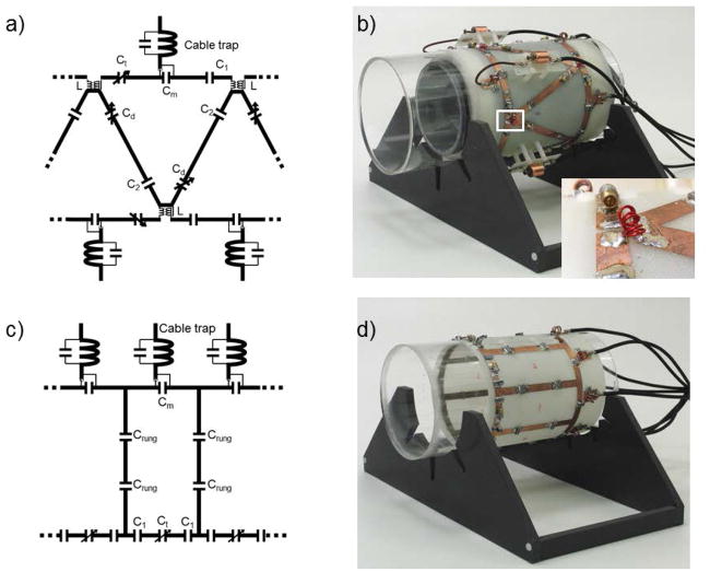
An 8-channel cylindrical array of triangular coils was built on a 15.24cm diameter acrylic cylinder. The conductive structures were machined from FR4 circuit boards, with all conductors having 1cm width. The length of the coil array was 12.5cm. The triangular shape brought the corners of next-nearest neighbors close together (Fig. 1a), which allowed a pair of counter-wound inductors L to be placed such that the next-nearest neighbors can be decoupled (Fig. 1b). The mutual inductance of the pair could then be mechanically adjusted to cancel the mutual inductance of the corresponding coil elements and achieve satisfactory decoupling. Nearest-neighbor elements were decoupled capacitively through the variable capacitors Cd on the shared rungs.
Figure 1.
Circuit schematic (a) and photograph (b) of an 8-channel triangular coil array (containing cylindrical phantom) with a closeup of a pair of decoupling inductors; circuit schematic (c) and photograph (d) of an 8-channel rectangular coil array. Each drive port was fed across a capacitor and matched to 50 Ω individually.
Triangular elements were tuned independently to 297.2 MHz in the presence of a phantom (12 cm diameter, 24 cm length, εr = 57.5 and σ = 0.8 S/m at 297.2 MHz, see also (37)) via variable capacitors Ct, with nearest neighbors, and next-nearest neighbors decoupled. Through an iterative process, a value for C2 of 8.2 pF was chosen to be close to the Cd required to balance the currents, based on the total capacitance required on the rungs to decouple nearest neighbors, and the value of C1 (4.7 pF) was chosen to be close to Ct. Finally, each element was matched to a 50 Ω coaxial cable by a capacitor placed across the port, followed by a cable trap to block common mode currents (Fig. 1b). Because adjacent elements were fed from opposite ends of the array, the cables of four channels in the array were routed back across the elements. For each of those four cables, a platform in the center of the coil with an additional shielded cable trap was used to minimize the coupling between coils and the cable.
For comparison, an 8-channel rectangular coil array, equivalent to the degenerate birdcage structure (15), with identical overall dimensions to the triangular coil array was also constructed. Each element in the array was rectangular in shape, with 8 capacitors distributed around each loop (Fig 1c). The nearest neighbors were decoupled by shared capacitors Crung on the rungs, and no next-nearest neighbor decoupling was applied. Each element was tuned to 297.2 MHz independently via capacitor Ct with the presence of the same cylindrical phantom, and the values of capacitors C1 (6.9 pF) and Crung (9.4 pF) were determined in a similar method as for C1 and C2 in the triangular coil array. Each element was matched to 50 Ω by a capacitor placed across the port, and each transmission cable included a cable trap to block common mode currents (Fig 1d).
Both triangular and rectangular elements were evaluated on the bench to assess the loaded-to-unloaded quality factor (Q) ratio and decoupling to neighboring coils. Q was assessed by transmission measurements (S12) on a network analyzer (model E5071C, Agilent) for a disconnected element with a pair of decoupled inductive probes coupled to the isolated coil with and without loading by a phantom. Coupling between two given elements were made with S12 with all the other elements of the array connected to 50 Ω terminators.
After the bench measurements, both arrays were interfaced to a 7T scanner with 8 channel parallel transmit capability (Siemens, Erlangen) using an in-house built transmit-receive interface. Phases to the elements were chosen to create constructive interference (circularly-polarized excitation) at the center of the phantom by finding the phase of each channel there and compensating the difference. To determine the RF voltage needed to achieve a 90 degree flip angle in the center of the phantom, a turbo-FLASH based B1-mapping sequence was used(TR/TE/BW=10000/2.1/1002, FOV=256mm×128mm, Matrix=128×64, Slice = 5 mm). The scanner transmitter reference voltage was defined as the voltage needed to achieve a 180 degree flip angle with a 1 ms square pulse. The B1+ map of the 8-channel cylindrical triangular coil array was compared with the rectangular coil array using color scaled flip angle maps in the central transverse and coronal slices. In addition to the central transverse slice, B1+ maps were acquired at different locations along z (H40mm and F40mm) of each coil array for offline RF shimming. For each array, a set of shimming parameters was determined to optimize the homogeneity of a central region of interest on the center slice, and the same parameters were also applied to the off-center transverse slices. To quantitatively compare the performance of the arrays, Normalized Root-Mean-Squared Error (NRMSE), which was defined as the standard deviation of the differences between actual shimming results and desired patterns(uniform excitations) normalized by the mean values of desired patterns, was calculated for each slice.
SNR was measured using a gradient echo acquisitions both with (signal measurement) and without (noise measurement) RF excitation and calculated according to the “Kellman” method (38) (TR/TE/BW=200/4.1/300, FOV=220mm, Matrix=256, Slice = 3 mm). For a geometry (g) factor comparison between the two arrays, raw k-space data were acquired with the same cylindrical phantom. The same gradient-echo sequence was used, but with field of view set tightly around the phantom to maximize aliasing. Inverse g factor maps were calculated in a transverse slice with various acceleration factors (R=3×, 2×2), and in a coronal slice with acceleration factors R = 2× and 3× along the z direction. The g factor maps were plotted as the inverse g factor 1/g, representing the fraction of the SNR obtained compared to the ideal case in which there is no noise amplification in the SENSE reconstruction (7).
Results
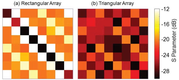
For the rectangular coil array loaded by the phantom, the coupling between any two next-nearest neighbors was approximately −11.6 dB when only those coils were active. It proved difficult to decouple nearest neighboring coils through adjustment of the capacitors in their shared legs, but when two nearest neighbors were in isolation it was possible to achieve isolation of approximately −15 dB. When all coils were active, however, the distribution of coupling changed, with much less coupling between next-nearest neighbors (~−20 dB) and higher coupling between neighbors (~−12 dB), summarized in Figure 2a. In addition, there was strong coupling between coils on opposite sides of the phantom. In contrast, the triangular coil array was very straightforward to decouple since once a coil was decoupled from its neighbors and its next-nearest neighbors it was largely unaffected by any changes to the rest of the array. Coupling between elements was −20 dB or less for all coil pairs (Fig. 2b). Qunloaded/Qloaded was 10 for the rectangular coil array and 5.7 for the triangular coil array.
Figure 2.
S-parameters of the rectangular coil array (a) and the triangular coil array (b) with the cylindrical phantom loaded. In contrast to −12 dB average coupling between nearest neighbors in the rectangular coil array, coupling between triangular coil array elements was −20 dB or better for all pairs.
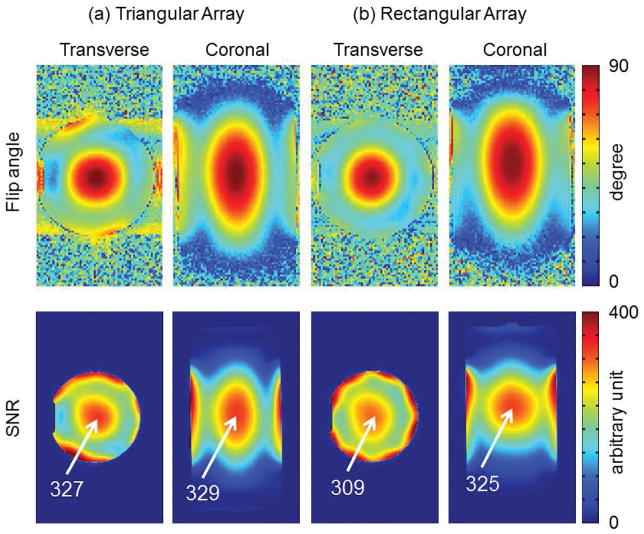
The scanner transmitter reference voltage for the rectangular coil array and the triangular coil array were 43 and 41 volts per channel, respectively. The overall excitation patterns (Figure 3, top row) were very similar for both arrays, apart from a bias towards the driving end of the rectangular coil array (Fig. 3b and Supplementary Figure S1). Sum-of-square SNR plots are shown in Figure 3, bottom row. Both 8-channel arrays achieved comparable SNR in the central region where flip angles were calibrated (90°).
Figure 3.
Comparison of the Flip angle (top) and SNR (bottom) between the triangular coil array (a) and the rectangular coil array (b). Phases to transmit channels were set to produce constructive interference in the center of the phantom. The overall excitation and SNR patterns were very similar for both coil arrays.
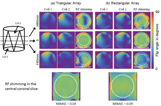
Looking at the B1+ field diversity, it can be seen that although all coils behave similar in a central transverse slice, neighboring coils 1 and coil 2 alternate in intensity when moving along z for the triangular coil array (Fig. 4a) but not for the rectangular coil array (Fig. 4b). When shimming on the central transverse slice, both arrays provide comparable performance on that slice, and the NRMSE is 0.04 for the triangular coil array and 0.06 for the rectangular coil array. However, the homogeneity on off-center transverse slices are then notably worse for the triangular array than for the rectangular array (NRMSE 0.35 vs 0.2 for the triangular array vs rectangular array on the H40mm slice and 0.35 vs 0.4 on the F40mm slice), because the number of effective coil element is reduced and the field distributions for each coil are different on different slices for the triangular array. Both arrays show satisfactory RF shimming results for the central coronal slice (Fig. 4, bottom), where the triangular array, having greater diversity of coil field patterns in the z direction, provides slightly better homogeneity than the rectangular array (0.04 NRMSE for the triangular coil array comparing to 0.09 NRMSE for the rectangular coil array).
Figure 4.
Comparison of the flip angle distribution for two adjacent channels and RF shimming results (with all eight channels) in triangular coil array (a) and rectangular coil array (b), in different transverse slices along z direction (center and 40mm in either direction). Coil 1 and coil 2 alternate in intensity when moving along z for the triangular array but not for the rectangular array. These additional variations in the B1 profile also affect the RF shimming performance of the triangle array. Compared to the rectangular array, RF shim configurations designed for the central slice in the triangle array perform less well off-center where the triangle coil has fewer effective elements. When shimming on a coronal plane, however, the additional variation in the B1 profiles help to create more uniform solutions.
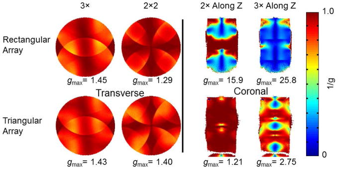
Both arrays also show similar 1/g factor maps in the center transverse plane (Fig. 5). In the coronal plane, however, a clear difference becomes apparent. In contrast to the strong noise amplification observed with the rectangular coil array, the triangular coil array showed excellent parallel imaging capability in the z direction. The maximum g factor was 13.1-fold lower in the 2× (along z) accelerated case and 9.3-fold lower in the 3× (along z) accelerated case.
Figure 5.
Inverse g factor maps for the rectangular coil array (top row), and the triangular coil array (bottom row), in the central transverse plane (left two columns), and coronal plane (right two columns). All maps are rendered with the same color scale for comparison; low values (blue) show areas with a high g factor and associated noise amplification. The peak g factor value for each case is shown below each map. The potential for acceleration in the z direction is a unique advantage of the array with triangular shaped elements.
Discussion
In this study we constructed and characterized an RF array design with triangular shaped elements, providing both diversity in field patterns in the z direction and excellent control over decoupling between nearest and next-nearest neighboring coils. A cylindrical prototype demonstrated both these advantages over a similar rectangular coil array. The benefit of making coil elements in a triangular shape was assessed in measurements through B1+, SNR and g factor maps.
By tilting the rungs to form triangles, the next-nearest neighbor decoupling could be achieved through pairs of counter-wound inductors. The function of the proposed decoupling mechanism in the triangular coil array was clearly demonstrated in the comparison of S-parameters to those in the rectangular coil array. The well decoupled cylindrical triangular coil array also exhibited slightly higher power efficiency than the rectangular coil array of the same size, and the SNR performance was comparable between the two arrays.
The better RF shimming results for the central coronal slice (Fig. 4, bottom) demonstrates the advantage of B1+ variation in the longitudinal direction with the triangular array. However, when shimming on the center transverse slice, the triangular array provided worse results in off-center transverse slices due to the reduced number of effective coil elements and differing coil-specific field patterns. The rectangular array provided somewhat reasonable shimming results across the slices, with some performance degradation in the slice 40 mm inferior to the center, which is likely due to the drop of B1+ intensities as the rectangular array was driven from the superior end. We did not fully demonstrate the performance of the proposed design in parallel transmission, as there is no universally accepted metric to estimate the performance of transmit arrays. Because of the principle of reciprocity and correlations between transmit and receive fields, the g factor, which is widely used to assess the parallel imaging performance of coils, was used to validate the triangular coil array design. The g factors for acceleration in the z direction were much lower for the cylindrical triangular coil array than for the rectangular coil array. Although the g factors for the two coils are similar for acceleration in central transverse plane, the acceleration ability for the triangular coil array suffers from having fewer effective elements near the either end of the coil.
In reception, the single-row 8-channel triangular coil array used here is not competitive with designs having many more receiving elements in terms of either peripheral SNR or g factors. However, given the hardware limitation that most commercially available 7T scanners have only up to 8 individual power amplifiers for transmission, an RF transmit array with limited elements is preferable for accelerated transmission. To improve general SNR and reception acceleration performance, a separate close-fitting receive-only array with a larger number of coil elements could be integrated into a transmit-only or transmit/receive triangular coil array.
In our experiments, the triangular coil array was built on a 15.24 cm diameter cylinder, which is too small for most in vivo applications. Rescaling the design, without changing the number of elements, may be challenging. Large loop elements can be difficult to tune at high frequencies, such as 297.2 MHz for 7T proton imaging, due to the need for very small capacitor values. To reduce the tuning challenges, the triangular coil array could be enclosed in a conductive shield (39). The shield should be slotted in a pattern following the arrangement of the coil conductors, and adjacent sections connected with large value capacitors (like 330 pF at 297.2 MHz) to prevent the flow of low-frequency eddy currents induced by the gradients.
Supplementary Material
Supplementary Figure S1: The flip angle map and corresponding cross-sectional plots at different positions (H40mm, 0, F40mm) in the central coronal slice for the rectangular coil array. Low intensities of the F40mm plot was due to that the rectangular coil array was driven from the single end (head side).
Footnotes
Disclosures: All authors state that they have no conflicts of interest.
References
- 1.Wiggins GC, Triantafyllou C, Potthast A, Reykowski A, Nittka M, Wald LL. 32-channel 3 Tesla receive-only phased-array head coil with soccer-ball element geometry. Magn Reson Med. 2006;56(1):216–223. doi: 10.1002/mrm.20925. [DOI] [PubMed] [Google Scholar]
- 2.Keil B, Blau JN, Biber S, Hoecht P, Tountcheva V, Setsompop K, Triantafyllou C, Wald LL. A 64-channel 3T array coil for accelerated brain MRI. Magn Reson Med. 2013;70(1):248–258. doi: 10.1002/mrm.24427. [DOI] [PMC free article] [PubMed] [Google Scholar]
- 3.Keil B, Alagappan V, Mareyam A, McNab JA, Fujimoto K, Tountcheva V, Triantafyllou C, Dilks DD, Kanwisher N, Lin W, Grant PE, Wald LL. Size-optimized 32-channel brain arrays for 3 T pediatric imaging. Magn Reson Med. 2011;66(6):1777–1787. doi: 10.1002/mrm.22961. [DOI] [PMC free article] [PubMed] [Google Scholar]
- 4.Roemer PB, Edelstein WA, Hayes CE, Souza SP, Mueller OM. The NMR phased array. Magn Reson Med. 1990;16(2):192–225. doi: 10.1002/mrm.1910160203. [DOI] [PubMed] [Google Scholar]
- 5.Keil B, Wald LL. Massively parallel MRI detector arrays. J Magn Reson. 2013;229:75–89. doi: 10.1016/j.jmr.2013.02.001. [DOI] [PMC free article] [PubMed] [Google Scholar]
- 6.Sodickson DK, Manning WJ. Simultaneous acquisition of spatial harmonics (SMASH): fast imaging with radiofrequency coil arrays. Magn Reson Med. 1997;38(4):591–603. doi: 10.1002/mrm.1910380414. [DOI] [PubMed] [Google Scholar]
- 7.Pruessmann KP, Weiger M, Scheidegger MB, Boesiger P. SENSE: sensitivity encoding for fast MRI. Magn Reson Med. 1999;42(5):952–962. [PubMed] [Google Scholar]
- 8.Griswold MA, Jakob PM, Heidemann RM, Nittka M, Jellus V, Wang J, Kiefer B, Haase A. Generalized autocalibrating partially parallel acquisitions (GRAPPA) Magn Reson Med. 2002;47(6):1202–1210. doi: 10.1002/mrm.10171. [DOI] [PubMed] [Google Scholar]
- 9.Collins CM, Liu WZ, Schreiber W, Yang QX, Smith MB. Central brightening due to constructive interference with, without, and despite dielectric resonance. J Magn Reson Imaging. 2005;21(2):192–196. doi: 10.1002/jmri.20245. [DOI] [PubMed] [Google Scholar]
- 10.Van De Moortele PF, Akgun C, Adriany G, Moeller S, Ritter J, Collins CM, Smith MB, Vaughan JT, Ugurbil K. B-1 destructive interferences and spatial phase patterns at 7 T with a head transceiver array coil. Magnet Reson Med. 2005;54(6):1503–1518. doi: 10.1002/mrm.20708. [DOI] [PubMed] [Google Scholar]
- 11.Vaughan JT, Garwood M, Collins CM, Liu W, DelaBarre L, Adriany G, Andersen P, Merkle H, Goebel R, Smith MB, Ugurbil K. 7T vs. 4T: RF power, homogeneity, and signal-to-noise comparison in head images. Magn Reson Med. 2001;46(1):24–30. doi: 10.1002/mrm.1156. [DOI] [PubMed] [Google Scholar]
- 12.Tropp J. Image brightening in samples of high dielectric constant. J Magn Reson. 2004;167(1):12–24. doi: 10.1016/j.jmr.2003.11.003. [DOI] [PubMed] [Google Scholar]
- 13.Vaughan JT, Adriany G, Garwood M, Yacoub E, Duong T, DelaBarre L, Andersen P, Ugurbil K. Detunable transverse electromagnetic (TEM) volume coil for high-field NMR. Magn Reson Med. 2002;47(5):990–1000. doi: 10.1002/mrm.10141. [DOI] [PubMed] [Google Scholar]
- 14.Adriany G, Van de Moortele PF, Wiesinger F, Moeller S, Strupp JP, Andersen P, Snyder C, Zhang X, Chen W, Pruessmann KP, Boesiger P, Vaughan T, Ugurbil K. Transmit and receive transmission line arrays for 7 Tesla parallel imaging. Magn Reson Med. 2005;53(2):434–445. doi: 10.1002/mrm.20321. [DOI] [PubMed] [Google Scholar]
- 15.Alagappan V, Nistler J, Adalsteinsson E, Setsompop K, Fontius U, Zelinski A, Vester M, Wiggins GC, Hebrank F, Renz W, Schmitt F, Wald LL. Degenerate mode band-pass birdcage coil for accelerated parallel excitation. Magn Reson Med. 2007;57(6):1148–1158. doi: 10.1002/mrm.21247. [DOI] [PubMed] [Google Scholar]
- 16.Vernickel P, Roschmann P, Findeklee C, Ludeke KM, Leussler C, Overwag J, Katscher U, Grasslin I, Schunemann K. Eight-channel transmit/receive body MRI coil at 3T. Magnet Reson Med. 2007;58(2):381–389. doi: 10.1002/mrm.21294. [DOI] [PubMed] [Google Scholar]
- 17.Rahbar H, Partridge SC, DeMartini WB, Gutierrez RL, Parsian S, Lehman CD. Improved B1 homogeneity of 3 tesla breast MRI using dual-source parallel radiofrequency excitation. J Magn Reson Imaging. 2012;35(5):1222–1226. doi: 10.1002/jmri.23571. [DOI] [PMC free article] [PubMed] [Google Scholar]
- 18.Willinek WA, Gieseke J, Kukuk GM, Nelles M, Konig R, Morakkabati-Spitz N, Traber F, Thomas D, Kuhl CK, Schild HH. Dual-Source Parallel Radiofrequency Excitation Body MR Imaging Compared with Standard MR Imaging at 3. 0 T:Initial Clinical Experience. Radiology. 2010;256(3):966–975. doi: 10.1148/radiol.10092127. [DOI] [PubMed] [Google Scholar]
- 19.Hoult DI, Phil D. Sensitivity and power deposition in a high-field imaging experiment. J Magn Reson Imaging. 2000;12(1):46–67. doi: 10.1002/1522-2586(200007)12:1<46::aid-jmri6>3.0.co;2-d. [DOI] [PubMed] [Google Scholar]
- 20.Ibrahim TS, Lee R, Baertlein BA, Abduljalil AM, Zhu H, Robitaille PML. Effect of RF coil excitation on field inhomogeneity at ultra high fields: A field optimized TEM resonator. Magn Reson Imaging. 2001;19(10):1339–1347. doi: 10.1016/s0730-725x(01)00404-0. [DOI] [PubMed] [Google Scholar]
- 21.Brunner DO, Paska J, Froehlich J, Pruessmann KP. Traveling-wave RF shimming and parallel MRI. Magn Reson Med. 2011;66(1):290–300. doi: 10.1002/mrm.22817. [DOI] [PubMed] [Google Scholar]
- 22.Curtis AT, Gilbert KM, Klassen LM, Gati JS, Menon RS. Slice-by-slice B1+shimming at 7 T. Magnet Reson Med. 2012;68(4):1109–1116. doi: 10.1002/mrm.23319. [DOI] [PubMed] [Google Scholar]
- 23.Katscher U, Bornert P, Leussler C, van den Brink JS. Transmit SENSE. Magn Reson Med. 2003;49(1):144–150. doi: 10.1002/mrm.10353. [DOI] [PubMed] [Google Scholar]
- 24.Zhu Y. Parallel excitation with an array of transmit coils. Magn Reson Med. 2004;51(4):775–784. doi: 10.1002/mrm.20011. [DOI] [PubMed] [Google Scholar]
- 25.Brunner DO, Pruessmann KP. Optimal design of multiple-channel RF pulses under strict power and SAR constraints. Magn Reson Med. 2010;63(5):1280–1291. doi: 10.1002/mrm.22330. [DOI] [PubMed] [Google Scholar]
- 26.Zhu Y, Alon L, Deniz CM, Brown R, Sodickson DK. System and SAR characterization in parallel RF transmission. Magn Reson Med. 2012;67(5):1367–1378. doi: 10.1002/mrm.23126. [DOI] [PMC free article] [PubMed] [Google Scholar]
- 27.Lee W, Boskamp E, Grist T, Kurpad K. Radiofrequency current source (RFCS) drive and decoupling technique for parallel transmit arrays using a high-power metal oxide semiconductor field-effect transistor (MOSFET) Magn Reson Med. 2009;62(1):218–228. doi: 10.1002/mrm.21988. [DOI] [PubMed] [Google Scholar]
- 28.Chu X, Yang X, Liu Y, Sabate J, Zhu Y. Ultra-low output impedance RF power amplifier for parallel excitation. Magn Reson Med. 2009;61(4):952–961. doi: 10.1002/mrm.21908. [DOI] [PMC free article] [PubMed] [Google Scholar]
- 29.Wang J. A novel method to reduce the signal coupling of surface coils for MRI. Proceedings of the 4th Annual Meeting of ISMRM; New York. 1996; p. 1434. [Google Scholar]
- 30.Pinkerton R, Barberi E, Menon R. A high field transceiver/receive-only surface coil array. Proceedings of the 13th Annual Meeting of ISMRM; Miami Beach, Florida, USA. 2005; p. 906. [Google Scholar]
- 31.Avdievich NI, Pan JW, Hetherington HP. Resonant inductive decoupling (RID) for transceiver arrays to compensate for both reactive and resistive components of the mutual impedance. Nmr in Biomedicine. 2013;26(11):1547–1554. doi: 10.1002/nbm.2989. [DOI] [PMC free article] [PubMed] [Google Scholar]
- 32.de Zwart JA, Ledden PJ, Kellman P, van Gelderen P, Duyn JH. Design of a SENSE-optimized high-sensitivity MRI receive coil for brain imaging. Magnet Reson Med. 2002;47(6):1218–1227. doi: 10.1002/mrm.10169. [DOI] [PubMed] [Google Scholar]
- 33.Jevtic J. Ladder networks for capacitive decoupling in phased-array coils. Proceedings of the 9th Annual Meeting of ISMRM; Glasgow, Scotland, UK. 2001; p. 17. [Google Scholar]
- 34.Gilbert KM, Belliveau JG, Curtis AT, Gati JS, Klassen LM, Menon RS. A conformal transceive array for 7 T neuroimaging. Magnet Reson Med. 2012;67(5):1487–1496. doi: 10.1002/mrm.23124. [DOI] [PubMed] [Google Scholar]
- 35.Shajan G, Kozlov M, Hoffmann J, Turner R, Scheffler K, Pohmann R. A 16-Channel Dual-Row Transmit Array in Combination with a 31-Element Receive Array for Human Brain Imaging at 9. 4 T. Magnet Reson Med. 2014;71(2):870–879. doi: 10.1002/mrm.24726. [DOI] [PubMed] [Google Scholar]
- 36.Adriany G, Gozubuyuk A, Auerbach E, Van de Moortele P, Andersen P, Vaughan J, Ugurbil K. A 32 channel Transmit/Receive transmission line head array for 3D RF Shimming. Proceedings of the 15th Annual Meeting of ISMRM; Berlin, Germany. 2007; p. 166. [Google Scholar]
- 37.Duan Q, Duyn JH, Gudino N, de Zwart JA, van Gelderen P, Sodickson DK, Brown R. Characterization of a dielectric phantom for high-field magnetic resonance imaging applications. Med Phys. 2014;41(10):102303. doi: 10.1118/1.4895823. n/a. [DOI] [PMC free article] [PubMed] [Google Scholar]
- 38.Kellman P, McVeigh ER. Image reconstruction in SNR units: A general method for SNR measurement. Magnet Reson Med. 2005;54(6):1439–1447. doi: 10.1002/mrm.20713. [DOI] [PMC free article] [PubMed] [Google Scholar]
- 39.Chen G, Cloos MA, Lakshmanan K, Sodickson DK, Wiggins GC. A Shielded 8 Channel TxRx Head Array with Triangular Elements and Second Order Decoupling. Proceedings of the 21st Annual Meeting of ISMRM; Salt Lake City, Utah, USA. 2013; p. 4409. [Google Scholar]
Associated Data
This section collects any data citations, data availability statements, or supplementary materials included in this article.
Supplementary Materials
Supplementary Figure S1: The flip angle map and corresponding cross-sectional plots at different positions (H40mm, 0, F40mm) in the central coronal slice for the rectangular coil array. Low intensities of the F40mm plot was due to that the rectangular coil array was driven from the single end (head side).


