Abstract
Purpose
To build and evaluate a small-footprint, lightweight, high-performance 3.0T MRI scanner for advanced brain imaging with image quality that is equal to or better than conventional whole-body clinical 3.0T MRI scanners, while achieving substantial reductions in installation costs.
Methods
A conduction-cooled magnet that uses only < 12 liters of liquid helium in a gas-charged sealed system, and standard NbTi wire and weighs ~2000 kg was developed. A 42-cm inner diameter gradient coil with asymmetric transverse axes was developed to provide patient access for head and extremity exams, while minimizing magnet-gradient interactions that adversely impact image quality. The gradient coil was designed to achieve simultaneous operation of 80 mT/m peak gradient amplitude at a slew rate of 700 T/m/s on each gradient axis using readily-available, 1 MVA gradient drivers.
Results
In a comparison of anatomical imaging in 16 patients using T2W-3D-FLAIR between the compact 3T and whole-body 3T, image quality was assessed as equivalent to or better across several metrics. The ability to fully utilize a high slew rate of 700 T/m/s simultaneously with 80 mT/m maximum gradient amplitude resulted in improvements in image quality across EPI, diffusion imaging, and anatomical imaging of the brain.
Conclusions
The compact 3T MRI system has been in continuous operation at the Mayo Clinic since March, 2016. To date, over 200 patient studies have been completed, including 96 comparison studies with a clinical 3T whole-body MRI. The increased gradient performance has reliably resulted in consistently improved image quality.
Introduction
Magnetic Resonance Imaging (MRI) has proved to be an excellent imaging platform for improving our understanding of structural and functional connectivity in the brain as well as neuroanatomy. It has been proposed that MRI can potentially provide a better understanding of neurocognitive disorders, dementia, depression, traumatic brain injury, and stroke. The mainstay to image the brain has been 3.0T MRI. However, access to this imaging technology has been limited due to the costs of installation and the space needed to site a conventional whole-body 3.0T MRI scanner. Typical clinical 3.0T MRI scanners weigh between 5–8,000 kg, and require 1–2,000 liters of liquid helium. The weight of the scanner and also the need to adequately vent gaseous helium (in the event of a magnet quench) limits placement options for conventional MRI systems. They are typically sited at locations closer to an exterior wall or ceiling, and also on the ground floor (if additional floor reinforcement is not practical for higher floors). The 0.5 mT (i.e., 5 Gauss) fringe field line for whole-body 3.0T MRI scanners typically extends to a 50–60 m2 footprint, making adequate space to site the scanner an important installation consideration, or requiring additional magnetic shielding.
Whole-body MRI scanners have been limited to maximum gradient amplitudes (Gmax) of between 50–80 mT/m and maximum slew rates (SRmax) of no more than 200 T/m/s. Because the inductance of the gradient coil scales as approximately r5 [1], where r is the radius of the gradient coil, increasing Gmax >80 mT/m requires substantially higher peak power, e.g., 8 MVA/axis to achieve 300 mT/m [2],. Increasing the gradient slew rate beyond 200 T/m/s in whole-body MRI systems is also not practical due to increased power requirements and also the physiologic limits imposed by peripheral nerve stimulation (PNS) [3,4].
Previous reports of smaller diameter, dedicated head-gradient coils have shown that the PNS threshold is substantially above that of whole-body gradients, allowing the use of gradient slew rates in excess of 200 T/m/s [5–7]. However, other head gradient coils developed for imaging the brain have not seen routine use, due either to deficiencies in active shielding, poor spatial linearity over the required 22–24 cm imaging field-of-view (FOV) for brain imaging [5,8–15], gradient heating, or the additional concomitant fields produced by an asymmetric design [16,17]. Regions of the brain such as the frontal lobe and the cerebellum could not be imaged without distortion due to poor spatial gradient linearity. Recently, a 33-cm inner diameter gradient insert capable of 200 mT/m gradient amplitude with good linearity over the brain was reported, focusing on the application of zero echo time imaging [7]. The small gradient coil inner diameter severely limits the use of a homogeneous B1 field transmit coil with a high-channel count (≥32 channels) receiver array.
In terms of gradient performance, a survey of prior work in head gradient coils yielded Gmax ranging from between 16 mT/m and 90 mT/m, with slew rates up to 400 T/m/s. However, none of these combined high Gmax (>50 mT/m) simultaneously with high SRmax. A previous commercially-offered head-only MRI system had a specification of 40 mT/m and 400 T/m/s [15]. A similar asymmetric gradient coil with an inner diameter of at least 40 cm or more was demonstrated at 7.0T with reported performance ranging from 50–80 mT/m and 333–700 T/m/s [18–20].
We attempt to address such limitations in whole-body MRI by developing a specialized, dedicated 3.0T MRI system (magnet and head-gradient) for imaging the brain and the extremities. The goal was to develop, design, and implement a Compact 3.0T (C3T) scanner with significant weight and siting advantages, but also superior imaging performance over any standard clinical or research whole-body MRI system operating at 3.0T. The 42-cm inner diameter gradient system described herein [21,22] provides simultaneous high Gmax (80 mT/m) and high SRmax (700 T/m/s).
Methods
Magnet Design
Previous work using Nb3Sn superconducting wire operating at 10K demonstrated that a 3,000kg 0.5T magnet could be built and operated routinely without using cryogens [23,24]. This earlier work, a conduction-cooled “double-doughnut” interventional 0.5T MRI system, established the proof-of-principle that a magnet could be maintained at superconducting temperatures using conduction-cooling only (i.e., with a pair of Gifford-McMahon (GM) cryo-coolers). However, Nb3Sn wire is substantially more expensive and difficult to work with compared to NbTi wire, making it less commercially viable and practical for a widely deployable MRI system.
The objective of the current work was to increase the field to 3.0T for a compact magnet to image the brain while using conventional NbTi superconducting wire at 4K, using a cryogenic system that requires no liquid helium supply or venting. This solution facilitates increased flexibility for siting the C3T magnet. In addition, the target weight for the magnet design was approximately one-third of the weight of a conventional 5–6,000 kg whole-body 3T MRI scanner, enabling the magnet to be transported to upper floors using a standard freight elevator, and conventional fork-lifts rather than with specialized heavy-lift cranes.
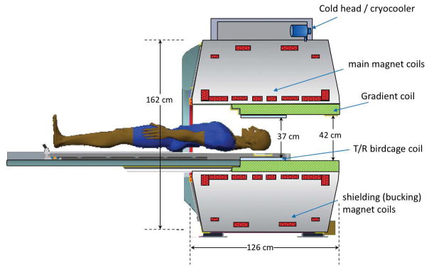
To accommodate a head-sized gradient coil with good linearity over a 26-cm diameter spherical volume (DSV), the C3T magnet has a warm-bore inner diameter of 62 cm. The use of conventional superconducting NbTi wire facilitates operation at 4K using a single two-stage 1.5W GM cryo-cooler (Model RDK-415A3, Sumitomo Heavy Industries, Allentown, PA, USA) to maintain the magnet coils at 4K. This resulted in increasing the total stored energy by a factor of three as compared to the previous cryogen-free interventional 0.5T MRI system [23,24]. The magnet uses a standard 8-coil design with 6 main coils and 2 shielding coils to contain the 5 Gauss line within a 4 m × 6 m area (Figure 1). The specifications of this magnet compared to a whole-body 3.0T MRI system can be found in Table 1(a).
Figure 1.
Illustration of the key components of the compact 3.0T MRI system showing the dimensions relative to a patient, the locations of the magnet coils, gradient coil, and the transmit/receive birdcage RF coil, together with the cold-head/cryo-cooler.
Table 1.
(a) Magnet and gradient design specifications of the compact 3.0T specialty MRI scanner compared to that of typical whole-body 3.0T MRI scanners. (b) Performance characteristics of the asymmetric gradient design. Although the maximum simultaneous gradient performance is 85 mT/m at 750 T/m/s, the system operates at a nominal 80 mT/m at 700 T/m/s to provide sufficient head-room for eddy current, linear shim, and concomitant gradient corrections.
| (a) | ||
|---|---|---|
| Whole-body 3.0T MRI | Compact 3.0T MRI | |
| Imaging FOV | 45–50 cm DSV | 26 cm DSV |
| Length | 160–175 cm | 126 cm |
| Width (OD) | 190–200 cm | 162 cm |
| Warm bore (ID) | 88–92 cm | 62 cm |
| Weight | 5,500 – 8,000 kg | <1,900 kg |
| Liquid Helium volume | 1,500–2,000 liters | 12 liters |
| 5G fringe field from center | 3 m × 5 m | 2 m × 3 m |
| Target field homogeneity (p-p) | < 1ppm (45–50 cm FOV) | < 1 ppm (26 cm DSV) |
| Gradient | ||
| Slew rate | 200 T/m/s | 700 T/m/s |
| Gradient amplitude | 50–80 mT/m | 80 mT/m |
| Inner diameter | 65–75 cm | 42 cm |
| Patient bore (head with RF coil) | 60–70 cm | 37 cm |
| Patient bore (shoulders) | 60–70 cm | 60 cm |
| Weight | 500–1,000 kg | 250 kg |
| (b) | |
|---|---|
| Gradient Coil Characteristic | Performance |
| Inner diameter | 42 cm |
| Outer diameter | 59 cm |
| Length | 92 cm |
| Linearity over 26-cm DSV | < 17% |
| Uniformity over 26-cm DSV | < 52% |
| Maximum driver current | 660 A |
| Nominal driver current | 620 A |
| Coil gain (gradient efficiency, η) [x y z] | 0.129/0.129/0.132 mT/m/A |
| Inductance, L [x y z] | 0.234/0.204/0.186 mH |
| Maximum slew rate @ 85 mT/m at 1500V | 708 T/m/s |
| Post-compensated eddy current [x y z] | < 0.08% |
| Net force at 660 A [x y z] | < 100 N |
| Net torque at 660 A [x y z] | < 50 Nm |
| Thermal capacity (cooling) | 25 kW continuous |
| Gr.m.s. at 100% duty cycle (at 320A r.m.s.) | 40 mT/m |
Central to the design is the use of conduction cooling with a helium gas-charged sealed system (that liquefies to < 12 liters of liquid helium) to provide a stable 4 K operational temperature, with a 1 K temperature margin to the critical temperature (Tc) of NbTi wire at the operating field. As a sealed cryogenic system is used, cryo-venting is not required (e.g., the installation at the Mayo Clinic), unlike conventional liquid helium bath-cooled MRI systems. In the unlikely event of a catastrophic magnet failure, the vented helium gas would occupy a volume of 9.1 m3 - for the minimum room size of 24 m2, the stratified helium gas would reach down 38 cm from the ceiling, well above the height of a 2-m tall adult, hence, mitigating the risk of asphyxiation.
An important consideration of the magnet design is the transmission of the cold-head vibrations to the magnet cold-mass. This can result in Bo-field oscillations that adversely impact image quality. Two approaches were used to reduce the coupling of the cold-head vibration to magnet cold-mass. The first was the use of a side-mounted mechanical sleeve that dampens the vibrational modes that can be transmitted through the magnet coil support structure suspension. The second was the use of flexible copper braids that thermally linked the cold-head to the close-loop recondenser, thus providing isolation of vibrations to the magnet cold-mass. The effectiveness of these measures was validated in a test-magnet assembly where High-Speed Stability (HSS) tests were performed with temporal resolution ≪ 1 Hz. The vibration decoupling design was validated in tests performed at 1 Hz and 0.5 Hz.
The magnetic field was mapped using a 24-probe magnetic field camera (MFC-3045, MetroLab Technology SA, Geneva, Switzerland), with the sensors mounted in a half-circle at a radius of 18 cm. The field measurements were made every 10-degrees azimuthally for 36 positions, covering a 36-cm DSV. Fitting to the spherical harmonics coefficients allows for the interpolation of the magnetic field at different DSV’s within the 36-cm DSV of the measured field probe positions. Passive shims, using iron chips mounted in shim trays mounted on the inner diameter of the magnet with 54 angular and 46 longitudinal shim positions, were then used to bring the inhomogeneity below 2 ppm over a 26-cm spherical imaging volume.
Radiofrequency Coils
A custom 16-rung birdcage transmit/receive coil was built to generate a homogeneous B1-field in the 26-cm imaging FOV. The radio-frequency (RF) coil’s 37-cm diameter is much larger than previous transmit coils for head-only systems, and easily accommodates a standard clinical 8-channel brain coil (InVivo Corp., Gainsville, FL, USA), or a 32-channel brain array (NOVA Medical, Inc., Wilmington, MA, USA). The rear-facing mirror presents the patient with a more open view to the rear of the magnet where different outdoor scenes can be displayed. This setup also allows the patient to view a video display for visual stimulation in fMRI studies, although we have not yet implemented this capability.
Gradient Design
For a smaller-sized gradient coil, an asymmetric gradient design was necessary [25] for the transverse gradient axes (i.e., physical x and y) to allow for patient access. This moves the imaging FOV towards the patient end of the gradient coil assembly and ensures that for >95% of individuals, the glabella reached the gradient isocenter (Figure 1). In addition, the asymmetric gradients were simultaneously force- and torque-balanced to minimize interactions with the magnet. Because the gradients were targeted for use in advanced diffusion imaging as well as fMRI, minimization of eddy currents was also a requirement.
The 42-cm gradient inner diameter achieves a maximal patient bore size while still allowing the gradient coil assembly to fit into the 62-cm warm bore of the C3T magnet with adequate clearance for mounting. The overall design resulted in a stepped bore profile, from 37-cm diameter at the patient’s head, to 42-cm at the patient’s shoulders (trapezius), and finally flaring to 60-cm to accommodate the arms and shoulders.
The solenoidal z-gradient is a fully symmetric design to achieve a short coil length and to avoid an undesirable Bo offset field (as in an asymmetric design). Hollow conductors used for all three gradient axes result in more efficient direct liquid cooling, enabling improved thermal management to handle the heat load for high duty-cycle operations. With this design, >25 kW can be removed, maintaining moderate operating temperatures and providing good thermal stability.
An added requirement was ability to visualize structures inferior to the brain down to the cervical spine C2/C3 vertebral junction without significant distortion, as determined by visual assessment by radiologists. This requirement provides a visual indication for gradient linearity and uniformity in the critical regions of the brain (such as the frontal lobe and the cerebellum).
System Electronics and Patient Handling
The C3T MRI system utilizes standard system electronics of a clinical whole-body 3.0T MRI system (SIGNA MR750w, GE Healthcare, Waukesha, WI, USA). A standard detachable SIGNA patient table was modified by removing all motorized components and adding a 3D-printed modular section to accommodate the different head and extremity coils. The advantage of utilizing the electronics of a standard clinical system is that the operation of the MRI scanner is essentially unchanged, allowing technologists to seamlessly transition from a clinical scanner to this specialized research scanner.
Human Subjects Studies
All studies conducted on human subjects were carried out in accordance with Institutional Review Board-approved protocols. These studies included assessments in patients to evaluate image quality and image artifacts, and comparison scans with a standard clinical whole-body 3.0T MRI system (GE SIGNA MR750). A total of 96 patients (52 female, and 44 male) were studied under IRB-approved protocols to compare imaging on the C3T MR scanner with a clinical 3.0T whole-body MR scanner. For the whole-body MR scanner, standard clinical protocols were used. The protocols for the C3T scanner were optimized to take full advantage of the higher Gmax and SRmax.
One comparison study is reported here. Sagittal T2-weighted 3D FLAIR of the brain was evaluated in 16 patients. Acquisition parameters were: 8-channel brain coil (for all studies); 256 × 256 acquisition matrix; 152 slice partitions with 1.2-mm slice thickness; TR=7600 ms; echo train length = 200; R=2 parallel acceleration. System-specific parameters were: TE=93.0 ms, TI=2025 ms, with echo-spacing = 4824 μs on the whole-body 3T. On the C3T scanner, TE=91.3 ms, TI=2060 ms, with echo-spacing = 3544 μs. The different parameters on the C3T scanner were the result of the difference in gradient performance, where the echo spacing was reduced by more than 1.1 ms (23% reduction). This protocol is part of the routine clinical protocol at our institution. The images were assessed independently by two experienced neuroradiologists and scored on a 5-point scale ([−2,−1,0,+1,+2]), with +2 indicating a preference for images from the C3T system, and −2 indicating a preference for images from the whole-body system. Scores of [−1,0,+1] were considered as equivocal or having a slight preference. Statistical significance was determined using a right-sided Wilcoxon Sign-Rank test [26].
For musculoskeletal studies of the knees and ankle/feet, and wrists, either a standard 16-channel GEM Flex coil (Neocoil, Pewaukee, WI, USA) or a 10-cm diameter transmit-receive birdcage coil (Medspira, Minneapolis, MN, USA), respectively, is used. With modular custom coil-holders the same patient table accommodates the head, scans of the knees with the patient entering the magnet feet-first, or the wrist with the patient either prone or decubitus, whichever is more comfortable. For scans of the knee, the subjects were able to fit both knees in the 37-cm patient bore with the 16-channel Flex coil.
Ramp sampling was implemented in all EPI acquisitions. In addition, a standard partial Fourier fraction of 0.75 was used for both the gradient echo EPI and also the spin-echo (diffusion) EPI acquisitions. With body-PNS limits, the target EPI readout plateau time to the total readout time (including the ramp sampling time) was set to 0.68. With the higher head-PNS limits, this ratio was set to 0.90, increasing the readout gradient amplitude. Hence, even if the echo-spacing time is halved, the gradient amplitude (and the readout bandwidth) is not necessarily doubled as it is a function of the ramp fraction of the readout.
Results
Magnet
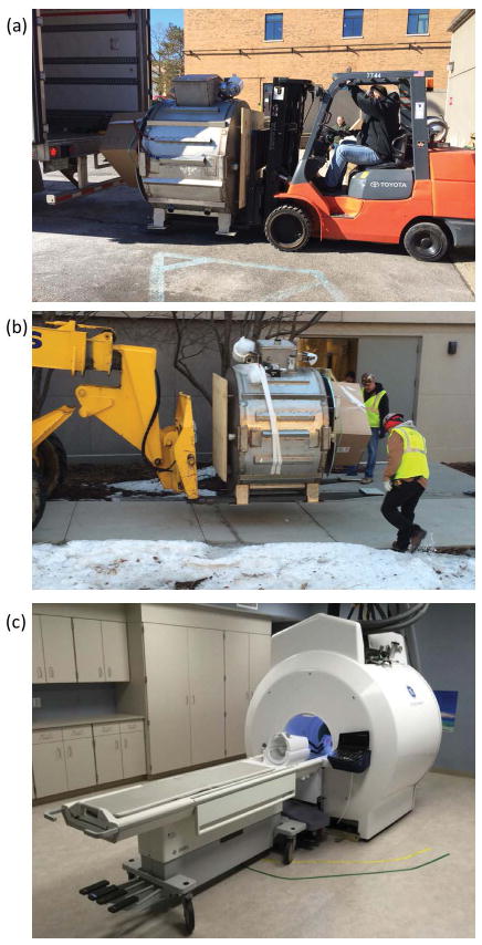
The magnet was shipped cold via a standard 53-foot (16.15 m) semi-trailer in two-days. Due to its relative light weight (2.1-ton magnet and gradient assembly), it was loaded and unloaded using commercially available forklifts (Figures 2a and 2b). The fully installed system is shown in Figure 2c. Immediately after initial installation, the magnet cryo-cooler was energized and the magnet cooled from 55 K to 4.15 K within 6-days (Figure 3). A limitation of this design is the longer cool-down time in the event the magnet warms to a higher temperature, e.g., during longer transportation time without power to the cryo-cooler.
Figure 2.
Loading (a) and unloading (b) of the compact 3.0T MRI scanner for transport using standard commercial 53-foot semi-trailers, and standard fork-lifts. (c) The completed and installed compact 3.0T MRI system at Mayo Clinic showing the detachable/dockable table and the 32-channel NOVA head coil mounted on the custom head-holder. Note the absence of a cryo-vent.
Figure 3.
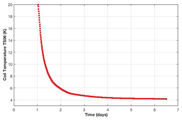
Magnet cool-down profile. Within 6-days after installation of the compact 3.0T MRI system, the magnet coil temperature reached 4.15K, which was sufficient to ramp the magnet to field.
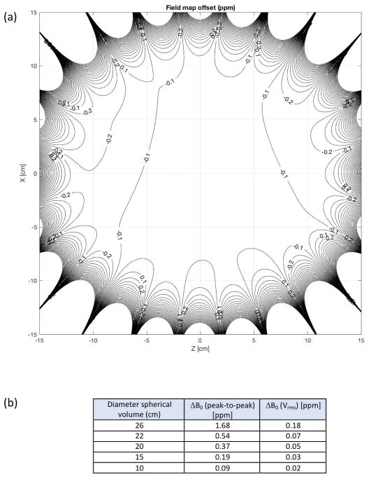
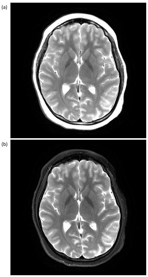
The magnet was successfully ramped to field at 3.0T with a current of <300 A using approximately 35 km of NbTi wire. After 24 hours, the magnet stability was measured as <0.01 ppm/hour (field drift), which was well within the 0.04 ppm/hour specified by standard acceptance criteria [27]. For this prototype magnet, the field homogeneity over a 26-cm DSV was measured at 1.68 ppm (peak-to-peak) or 0.18 (root-mean-squared (rms) variation (Vrms)), as shown in Figure 4. The homogeneity over a 24-cm DSV was 0.54 ppm (peak-to-peak) or 0.07 ppm (Vrms). Furthermore, the resultant magnetic field homogeneity provided good fat suppression over a 24-cm image FOV (Figure 5), consistent with the post-shimmed magnetic field camera plots (Figure 4).
Figure 4.
(a) Bz-field map after conventional passive shimming showing the field homogeneity of the compact 3T magnet in the coronal plane. (b) Measured field homogeneity at different diameter spherical volumes.
Figure 5.
T2-weighted Fast Spin Echo (FSE) images acquired with an 8-channel brain coil (22-cm FOV; 320×320 matrix; TE/TR = 98.7/4686 ms; 4-mm slices; 36 locations in 2:16) with (a) no fat suppression, and (b) with fat suppression. The uniformity of the fat suppression over the 22-cm FOV is an indication of the field homogeneity realized with the compact 3.0T magnet design.
The magnet stray field plot (Figure 6), showed that the 5 Gauss field line was well contained within a 6 m × 4 m area, which is much smaller than that for typical 3T MRI systems (10 m × 6 m). Consequently, the fall-off in the static magnetic field is much steeper than that encountered in whole-body MRI magnets. Static field gradient measurements [28] indicated that there were several hot-spots (areas of high static field gradients) in the fringe field and within the magnet bore that were greater than the 7.2 T/m but these were comparable to those found in whole-body 3.0T MRI scanners.
Figure 6.
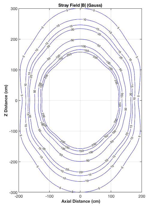
Stray field map outside of the compact 3.0T magnet showing the |B|-field lines from 5 to 200 Gauss (0.5–20 mT).
Quench cycle tests were also conducted on the C3T magnet by allowing the magnet temperature to rise above 5.5K by powering off the cryo-cooler. Unlike conventional helium bath-cooled magnets, no gaseous helium was released from this sealed system. Hence, there was no need for a specialized helium vent stack in the magnet scan room. To recover temperature and to ramp the magnet back up to field, the cryo-cooler was restarted to begin the cool-down cycle to 4K, and ramped to field. This recovery is in contrast to that in conventional helium bath magnets where about 1,000–2,000 liters of liquid helium are required to re-cool, and re-fill the magnet to operating levels.
Gradient
Systems assessments of gradient linearity, PNS, and acoustic sound pressure levels (SPL) were performed and the results were previously reported [29–31]. To summarize, the results indicated that the 10th order spherical harmonic correction with both even and odd terms resulted in a residual rms error < 0.36 mm [30]. As assessed from the clinical images, image blurring over the imaging FOV was not an issue in the post-distortion corrected images even with the <17% gradient non-linearity over the 26-cm FOV. Supporting Figure S1 shows the images in a grid phantom before and after correction. The gradient non-linearity could be an issue in quantitative diffusion as b-value would vary spatially. However, there are validated approaches to correct for this [32]. Extensive characterization of PNS was previously described by Lee, et al [31], indicating a PNS threshold substantially higher than that for whole-body gradients.
Wrap or cusp-artifact [33] (sometimes also called “annefact”), i.e., signal aliasing from excited tissue outside of the linear region of the gradient coil has not been observed with the C3T scanner. However, when the gradient was initially unit-tested as an insert gradient in a whole-body 3T scanner, the cusp-artifact was observed in some acquisitions, but was localized to the region below the cerebellum. The cusp-artifact is not an issue on the integrated C3T system because of the rapid drop-off in the B0-field [28]. Hence, regions outside of the linear region of the gradient coil excited by the transmit-receive RF coil resonates at frequencies far outside the receiver bandwidth.
At the maximum available current and voltage of the 1 MVA driver, 85 mT/m at 770 T/m/s was achieved. This was reduced to 80 mT/m at 700 T/m/s for scanner operation. Continuous operation (100% duty cycle) was demonstrated at an RMS gradient amplitude of 40 mT/m (Table 1(b)). Due to the direct cooling of the gradients, high duty cycle and high gradient amplitude tests resulted in measured gradient temperatures maintained at < 75°C (peak temperature). With a standard SIGNA DV system, the cooling cabinet supplied a 31 L/min of coolant flow with an inlet temperature of 18°C.
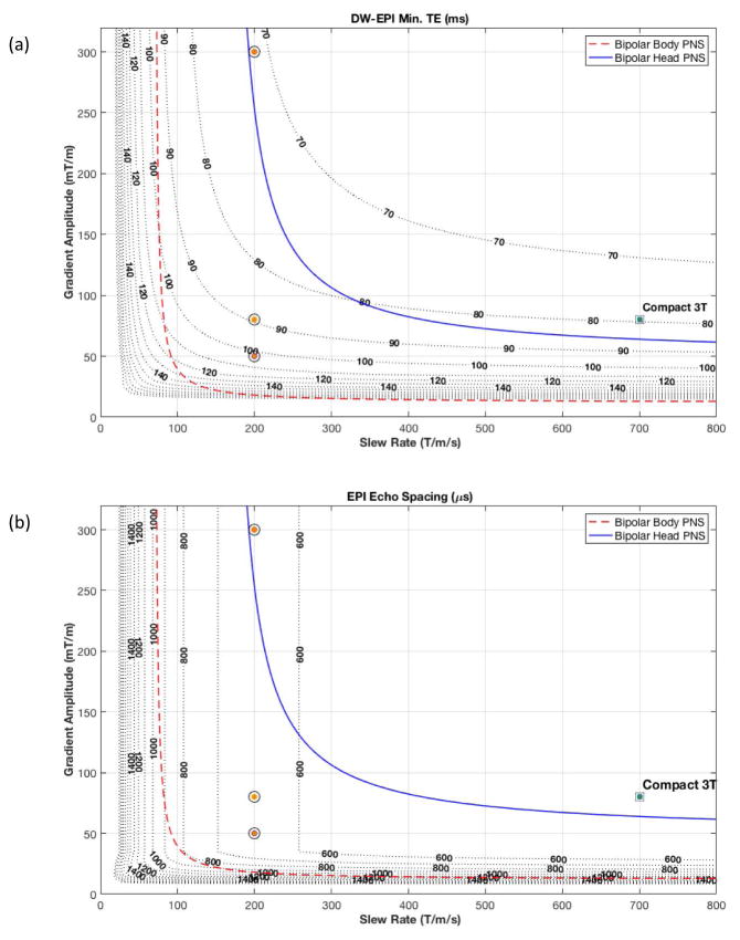
As shown in Figure 7, the maximum nominal operational point (80 mT/m and 700 T/m/s) for the C3T MRI scanner is just above the PNS threshold for head gradients. With a higher PNS threshold, the C3T system achieved a minimum echo time (TE) of 85 ms (Figure 7(a)) without parallel imaging (R=1) for a b=2,000 s/mm2 diffusion EPI pulse sequence. If parallel acceleration methods were employed, the TE times for the C3T head-gradient could be reduced to 60 ms (R=2), and 52 ms (R=3) at the cost of decreased image SNR by factors of 1/g√R, where g is the spatially-dependent coil geometry factor (g≥1), and R is the acceleration factor. The use of high acceleration factors in-plane could also reduce image distortion and improve slice efficiency by shortening the readout echo-train. However, our analysis suggests that it is more beneficial to shorten the EPI readout by increasing readout gradient amplitude, thereby increasing readout bandwidth and decreasing image SNR, by taking advantage of the higher slew rate and higher head PNS limit of the C3T scanner. That is because the latter allows for echo spacing to be shortened by about two, without requiring the readout amplitude to be increased by two. Furthermore, it is more beneficial to utilize through-plane simultaneous multi-slice acceleration [34] than in-plane parallel imaging, as the former has no sampling-related SNR loss.
Figure 7.
(a) Iso-contour curves of minimum TE times for a diffusion weighted EPI pulse sequence (with b=2,000 s/mm2; 24-cm FOV; 1.5 mm in-plane resolution; R=1; partial Fourier fraction of 75%) at a fixed receiver bandwidth, and ramp sampling enabled. (b) Iso-contours of the EPI readout echo spacing for the same acquisition. Overlaid are the PNS thresholds for bipolar pulses for the head-only compact 3T gradients (solid line) and whole-body gradients (dashed line). The circles indicate gradient specification for current clinical and research whole-body MR scanners, while the square indicates the performance of the compact 3T MRI.
The advantages of the increased slew rate impacts both the diffusion encoding gradient and also the EPI readout. For the diffusion encoding pulse, a high gradient amplitude is important for reducing the diffusion pulse width, while the shorter echo spacing (ESP) at a higher gradient slew rate results in shorter time between the end of the diffusion encoding lobe and the acquisition of the center of k-space lines [35]. Together, the higher gradient performance and higher PNS threshold result in reduced minimum TE times compared to whole-body MR scanners.
The impact of the higher PNS threshold on the echo spacing in an EPI acquisition is clearly shown in Figure 7(b) for a representative 24-cm FOV, 1.5 mm in-plane resolution scan. Assuming the same readout bandwidth, whole-body gradient systems can achieve echo-spacing of around 864 μs, whereas C3T achieves a 724 μs ESP. The higher PNS of the C3T allows utilization of higher receiver bandwidth. For instance, an increase in receiver bandwidth by about 34% results in further decrease in echo-spacing at the cost of a 16% SNR decrease, which is preferable to incurring an additional g-factor penalty in SNR if in-plane parallel imaging had been utilized. This is highly beneficial for minimizing geometric distortion, obtaining lower TE and consequently results in less signal dropouts that plague typical EPI acquisitions [36,37]. In previous work [38], improvements by 19% in signal intensity had been observed in regions susceptible to signal dropout, wherein reductions in echo-spacing (and image distortion) of up to 48% were also reported. Supporting Figure S2 shows the comparison between a Gradient-echo-EPI acquisition with the C3T system and a whole-body 3T scanner at the same TE time where the reduced distortion and signal dropout due to the high gradient slew rate is clearly seen.
As previously reported [39–41], additional corrections were implemented for the C3T system for concomitant gradients effects due to higher Gmax and the asymmetric gradient design [17]. These corrections used gradient pre-emphasis [40], as well as frequency tracking [39,41] in real-time, without the need for additional pulse sequence programming.
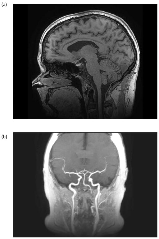
In an assessment of 96 subjects >99% of the images met or exceeded the gradient imaging specification of being able to visualize at least to the C2/C3 junction. The one subject where the C2/C3 junction was not visualized was severely kyphotic, and could not be properly positioned in the radiofrequency head-coil. Figure 8(a) shows a high spatial resolution (0.7-mm isotropic) 3D MP-RAGE sagittal image that illustrates the spatial coverage in a 23-cm FOV with minimal distortion down to the C3/C4 junction. As a result of the shorter RF transmit coil, inflowing blood is less saturated in the C3T. Consequently, the carotid and the middle cerebral arteries are visualized in a maximum intensity projection of the 3D MP-RAGE volume acquired on the compact 3.0T (Figure 8(b)). The carotid bifurcation was visualized in approximately 25% of the subjects studied and constituted an additional unexpected benefit for some patients.
Figure 8.
(a) Sagittal 3D MP-RAGE acquisition with 0.7 × 0.7 × 0.7 mm3 spatial resolution covering the entire brain in 8:25 with the 32-channel brain coil. Other acquisition parameters were: FOV = 22 cm, TE/TR = 3.1/7.3 ms; TI=1000 ms. Image detail of the brain and cerebellum is exquisite. Signal remains uniform and robust down to the level of the C2/C3 cervical interspace. There are only minimal susceptibility artifacts at the interface of the brain and paranasal sinuses (b) Maximum intensity projection of the 3D MP-RAGE acquisition showing high signal within the internal and external carotid arteries, and the proximal vertebral arteries. This bright blood extends more superiorly on the C3T MP-RAGE images, as the IR pulse does not extend into the lower neck and body as it would with conventional whole-body coil excitation.
The short length of the transmit RF coil also results in a smaller exposed body mass to RF, reducing the overall specific absorption rate (SAR) for the C3T scanner compared to whole-body MR scanners. Preliminary measurements indicated that the SAR for the C3T was approximately 20% less than that on whole-body MR scanners [42]. The lower SAR achieved with the C3T scanner has distinct advantages as a higher number of slices per repetition time (TR) can be realized, allowing a substantial reduction in scan time in certain circumstances.
Clinical Studies
All patients tolerated the scans well; there were no reports of discomfort or claustrophobia. For patients undergoing brain exams, only the upper torso above the upper forearm is in the magnet bore, reducing perception of a confined space (Supporting Figure S3). A further 105 patients (59 female, and 56 male) were scanned on other IRB-approved protocols, unrelated to the primary objective of comparing clinical protocols between the C3T scanner and a clinical whole-body 3T MR scanner. As such, over 200 patients and healthy volunteers have been successfully studied with the C3T scanner over a 16-month period, with acquired images of the brain acquired assessed to have good-to-excellent image quality (SNR and sharpness), as observed qualitatively (Figures 4,8, and 9).
Figure 9.
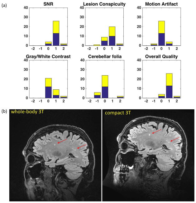
(a) Results of the right-side Wilcoxon Sign-Rank test from the assessment of 3D CUBE T2-weighted FLAIR image quality by 2 blinded neuroradiologists. (b) Comparison images in a patient with mild cognitive impairment showing white-matter lesions (arrows). Improved SNR and lesion conspicuity with the C3T system is evident from the shorter echo-spacing, resulting in reduced T2 blurring of the FSE echo train and overall improvement in image sharpness. The 8-channel brain coil was used in all instances with TR=7600 ms; 256 × 256 acquisition matrix in a 24-cm FOV; 152 1.2-mm partitions (0.94 mm × 0.94mm × 1.2 mm voxels); TE/TI=93.0 ms/2025 ms for the whole-body system, and TE/TI = 91.3 ms/2060 ms for the C3T system; echo-train length (ETL) = 200; in-plane acceleration R=2. The echo-spacing for the whole-body system was 4824 μs, and 3544 μs for the C3T scanner.
Reductions in minimum pulse sequence TE, ESP, pulse sequence repetition time (TR), or and increase number of slices acquired per TR (slice efficiency) were realized while retaining the same clinically relevant diagnostic information in the images. For a two-dimensional fast-recovery FSE/TSE scan with TR=3385 ms, 24-cm FOV, 3-mm thick slices, a 320 × 320 acquisition matrix, and 2 signal averages (NEX), the C3T system was able to complete a 50-slice scan in 3 min 24 s, compared to 5 min 5 s in a whole-body 3T clinical scanner. For a diffusion tensor imaging (DTI) sequence with a b-value of 5,000 s/mm2, 23-cm FOV, 2-mm thick sections, a 116×116 acquisition matrix, and TR=5800 ms, a minimum TE of 67 ms was achieved with a maximum of 72 slices per TR. This compared to a minimum TE of 110 ms and 52 slices per TR achieved with a whole-body 3T scanner, representing a 2.4-fold increase in diffusion image signal-to-noise ratio.
For the 3D-FLAIR comparison study, image SNR, lesion conspicuity, and grey-white matter contrast were rated as better on the C3T system (p-value < 0.01). Images from the C3T system were not significantly different from whole-body 3T images with respect to motion artifacts and conspicuity of the cerebellar folia (Figure 9a). Overall image quality was deemed as better on the C3T system (p-value<0.01). Considering the different aspects of image quality assessment, images from the C3T system was either equivalent to or better than that of whole-body 3T scanners. One reason for the image quality improvement is the reduction in the FSE echo-spacing by more than 1.1 ms or 23% compared to whole-body systems. As such, there is reduced T2 decay and blurring across all echoes in the long (ETL=200) FSE readout window (reduced with C3T system from 971 ms to 709 ms), allowing for shorter TE, improved image sharpness, and lesion conspicuity (Figures 9b). The higher slew rate could conversely be used to reduce overall scan time by keeping the duration of FSE readout window constant, and increasing the echo train length (ETL).
Musculoskeletal imaging with the compact 3.0T scanner also showed promise. The images have good image signal-to-noise ratio and the shorter echo spacing resulted in sharper images compared to whole-body scanners (Supporting Figure S4). In this example, the high slew rate of the C3T scanner reduced the overall data acquisition (ETL x echo spacing) time by 3.4 ms. Even with this small difference in overall data acquisition time, the structures in images acquired using the C3T scanner appeared to be more conspicuous. Further investigation is warranted to explore the reasons behind the observed results. Initial comparison studies have indicated statistically better image quality in the compact 3.0T scanner compared to a clinical whole-body 3.0T scanner [43].
Discussion
Since March 2016, the scanner has been in continuous operation. The asymmetric high-performance gradient that was specifically designed for this magnet platform demonstrated clear advantages, namely the ability to fully utilize a high slew rate (3.5 times that available with whole-body gradients) simultaneously on all three axes with a gradient amplitude of 80 mT/m with little or no PNS [31]. This allowed a substantial reduction in spatial distortion [38], and can improve image blurring, and signal dropouts in EPI, FSE, and also in magnetization-prepared fast gradient echo pulse sequences. The clear reduction in EPI echo spacing provides the flexibility to omit an in-plane parallel imaging acceleration factor of two needed typically for reducing image distortion; resulting in an increase in SNR, the level of increase depending on the change in bandwidth and the receiver coil g-factor. We speculate that at the same TE times, the reduction in signal drop out (Figure S2) is due to the irreversible dephasing from magnetic susceptibility throughout the entire EPI echo train. Reducing the echo spacing reduces the echo train time and may contribute to a reduction in signal drop out. Further investigation of this observation is warranted.
The gradient design successfully addressed the challenges of torque- and force-balancing, as well as controlling eddy currents in an asymmetric design. This was the key technology development to achieve such high performance with a low peak power. Although the asymmetric gradient coil was designed to operate in a smaller bore, lightweight 3T magnet, it is also able to operate as an insert gradient, similar to the asymmetric gradient design of Weiger, et al [7]. Both approaches utilize smaller diameter gradients to achieve high slew rates and high gradient amplitudes with <720 A and <1500 V. Such designs enable both imaging of the brain as well as the extremities (knees, feet, and wrists) with good linearity, force- and torque-balancing. As it is understood and accepted that whole-body gradients have reached a practical limit for power, maximum gradient amplitude, and maximum slew rate, specialized gradient coils, such as that described here and elsewhere [7,22,31], provide a path to achieving higher Gmax and SRmax for studying the human cerebral cortex at the mesoscale. Feinberg, et al, recently suggested that the combination of high Gmax and SRmax (80–160 mT/m and 400–600 T/m/s) is essential to achieving the optimal TE times for fMRI at 7T at spatial resolution better than 0.4-mm [44]. The faster slew rates allow for shorter minimum TE times for high spatial resolution EPI. For fMRI, this means that multi-echo fMRI approaches could be better explored [45], such that a shorter first echo TE time can be achieved as well as an echo acquired at the optimal TE time at 3T (40 ms).
The compact 3.0T platform demonstrated substantial improvements in imaging performance for specialized applications for brain and musculoskeletal (e.g., wrists, knees, feet) exams in a small footprint compared to conventional whole-body clinical MRI systems. The ability to install this compact system on upper floors, or interior rooms where cryo-venting is especially challenging, will improve accessibility to high quality diagnostic MRI studies of the brain, musculoskeletal regions, and also for pediatrics – all in an attractive package for space and installation costs.
Supplementary Material
Supporting Figure S1: Axial, coronal, and sagittal plane images of an American College of Radiology (ACR) large-phantom (J4459, JM Specialty Parts, San Diego, CA, USA) showing (left column) uncorrected images without gradient non-linearity correction (gradwarp) in 29-cm FOV, and (right column) images using 10th order correction. The two-dimensional images are 5-mm thick and the ACR phantom measures 20.4/19.0-cm in diameter and 16.5/14.8-cm in height (outer and inner dimensions, respectively).
Supporting Figure S2: Axial gradient-echo-EPI images at multiple locations in the brain showing (top row) C3T images with a 700 T/m/s slew rate, and (bottom row) images from a whole-body 3T system with 200 T/m/s slew rate. Acquisition parameters were 1.5-mm isotropic resolution, 21.6-cm FOV; TR=1800 ms; TE=40 ms (for both acquisitions). The reduction in signal drop-out with the higher slew rate is clear. Echo spacing reduced from 736 μs to 388 μs.
Supporting Figure 3: A healthy male volunteer (1.87 m tall, 84 kg) positioned for scanning in the 8-channel brain coil. Note that the hands and forearms remain outside the bore.
Supporting Figure S4: Fat suppressed two-dimensional axial fast spin echo (FSE) images of the knee acquired using a 16-channel Flex coil with R=1 (no acceleration). Acquisition parameters were: 16-cm FOV; 384×356 matrix; 3-mm slice thickness; TR=5626 ms. In both cases, 38 slices were acquired in 4:58. Image (a) was acquired using a clinical 3T GE 750 scanner with ESP=10.856 ms and TE=43.4 ms; image (b) which was acquired using the Compact 3T scanner with ESP=10.520 ms and TE=42.1 ms. There is slightly increased conspicuity and visualization of the common peroneal nerve on image (b) allowing identification of individual nerve fascicles (arrow).
Acknowledgments
The authors wish to acknowledge support from the NIH (R01EB010065 and U01EB02445), Cheryl Sabourin for invaluable support throughout this project, and Dan Rettmann for help with the systems operational configuration.
References
- 1.Turner R. Gradient coil design: a review of methods. Magn Reson Imaging. 1993;11:903–920. doi: 10.1016/0730-725x(93)90209-v. [DOI] [PubMed] [Google Scholar]
- 2.Setsompop K, Kimmlingen R, Eberlein E, et al. Pushing the limits of in vivo diffusion MRI for the Human Connectome Project. NeuroImage. 2013;80:220–233. doi: 10.1016/j.neuroimage.2013.05.078. [DOI] [PMC free article] [PubMed] [Google Scholar]
- 3.Reilly JP. Maximum pulsed electromagnetic field limits based on peripheral nerve stimulation: application to IEEE/ANSI C95.1 electromagnetic field standards. IEEE Trans Biomed Eng. 1998;45:137–141. doi: 10.1109/10.650371. [DOI] [PubMed] [Google Scholar]
- 4.Reilly JP. Peripheral nerve stimulation by induced electric currents: exposure to time-varying magnetic fields. Med Biol Eng Comput. 1989;27:101–110. doi: 10.1007/BF02446217. [DOI] [PubMed] [Google Scholar]
- 5.Chronik BA, Rutt BK. A comparison between human magnetostimulation thresholds in whole-body and head/neck gradient coils. Magn Reson Med. 2001;46:386–394. doi: 10.1002/mrm.1202. [DOI] [PubMed] [Google Scholar]
- 6.Zhang B, Yen Y-F, Chronik BA, McKinnon GC, Schaefer DJ, Rutt BK. Peripheral nerve stimulation properties of head and body gradient coils of various sizes. Magn Reson Med. 2003;50:50–58. doi: 10.1002/mrm.10508. [DOI] [PubMed] [Google Scholar]
- 7.Weiger M, Overweg J, Rösler MB, et al. A high-performance gradient insert for rapid and short-T2 imaging at full duty cycle. Magn Reson Med. 2017 doi: 10.1002/mrm.26954. [DOI] [PubMed] [Google Scholar]
- 8.Abduljalil AM, Aletras AH, Robitaille PM. 3D echo planar imaging: application to the human head. Magn Reson Med. 1995;34:144–148. doi: 10.1002/mrm.1910340203. [DOI] [PubMed] [Google Scholar]
- 9.Abduljalil AM, Aletras AH, Robitaille PM. Torque free asymmetric gradient coils for echo planar imaging. Magn Reson Med. 1994;31:450–453. doi: 10.1002/mrm.1910310415. [DOI] [PubMed] [Google Scholar]
- 10.Alsop DC, Connick TJ. Optimization of torque-balanced asymmetric head gradient coils. Magn Reson Med. 1996;35:875–886. doi: 10.1002/mrm.1910350614. [DOI] [PubMed] [Google Scholar]
- 11.Bowtell R, Peters A. Analytic approach to the design of transverse gradient coils with co-axial return paths. Magn Reson Med. 1999;41:600–608. doi: 10.1002/(sici)1522-2594(199903)41:3<600::aid-mrm24>3.0.co;2-e. [DOI] [PubMed] [Google Scholar]
- 12.Chronik BA, Alejski A, Rutt BK. Design and fabrication of a three-axis edge ROU head and neck gradient coil. Magn Reson Med. 2000;44:955–963. doi: 10.1002/1522-2594(200012)44:6<955::aid-mrm18>3.0.co;2-1. [DOI] [PubMed] [Google Scholar]
- 13.Tang F, Liu F, Freschi F, Li Y, Repetto M, Giaccone L, Wang Y, Crozier S. An improved asymmetric gradient coil design for high-resolution MRI head imaging. Phys Med Biol. 2016;61:8875–8889. doi: 10.1088/1361-6560/61/24/8875. [DOI] [PubMed] [Google Scholar]
- 14.Tomasi D, Xavier RF, Foerster B, Panepucci H, Tannús A, Vidoto EL. Asymmetrical gradient coil for head imaging. Magn Reson Med. 2002;48:707–714. doi: 10.1002/mrm.10263. [DOI] [PubMed] [Google Scholar]
- 15.De Wilde J, Price D, Williams J, Delakis I, Renaud C. Siemens Magnetom Allegra 3T MR imaging system: Technical evaluation and user information. 2003:1–64. [Google Scholar]
- 16.Wicklow K, Heid O. Method for the correction of artifacts in magnetic resonance images. 6,515,478. Patent No. 2003
- 17.Meier C, Zwanger M, Feiweier T, Porter D. Concomitant field terms for asymmetric gradient coils: consequences for diffusion, flow, and echo-planar imaging. Magn Reson Med. 2008;60:128–134. doi: 10.1002/mrm.21615. [DOI] [PubMed] [Google Scholar]
- 18.Endt vom A, Kimmlingen R, Riegler J, Eberlein E, Schmitt F. A High-Performance Head Gradient Coil for 7T Systems. Proceedings of the 14th Annual Meeting of the International Society of Magnetic Resonance in Medicine; 2006; p. 1370. [Google Scholar]
- 19.Endt Vom A, Riegler J, Eberlein E, Schmitt F, Dorbert U, Krueger G, Gruetter R. A High-Performance Head Gradient Coil for 7T Systems. Proceedings of the 15th Annual Meeting of ther International Society of Magnetic Resonance in Medicine; 2007; p. 451. [Google Scholar]
- 20.Kickler N, van der Zwaag W, Mekle R, Kober T, Marques JP, Krueger G, Gruetter R. Eddy current effects on a clinical 7T-68 cm bore scanner. Magn Reson Mater Phy. 2010;23:39–43. doi: 10.1007/s10334-009-0192-0. [DOI] [PubMed] [Google Scholar]
- 21.Mathieu JB, Lee SK, Budesheim EG, et al. Preliminary Evaluation of a High Performance Gradient Coil for 3T Head Specialty Scanner. Proceedings of the 21st Annual Meeting of the International Society of Magnetic Resonance in Medicine. 2013;2013:2708. [Google Scholar]
- 22.Mathieu J-B, Lee S-K, Graziani D, et al. Development of a dedicated asymmetric head-only gradient coil for high-performance brain imaging with a high PNS threshold. Proceedings of the 23rd Annual Meeting of the International Society of Magnetic Resonance in Medicine; 2015; p. 1019. [Google Scholar]
- 23.Laskaris ET, Ackermann R, Dorri B, Gross D, Herd K, Minas C. A cryogen-free open superconducting magnet for interventional MRI applications. IEEE Trans Appl Supercond. 1995;5:163–168. doi: 10.1109/77.402515. [DOI] [Google Scholar]
- 24.Schenck JF, Jolesz FA, Roemer PB, Cline HE, Lorensen WE, Kikinis R, Silverman SG, Hardy CJ, Barber WD, Laskaris ET. Superconducting open-configuration MR imaging system for image-guided therapy. Radiology. 1995;195:805–814. doi: 10.1148/radiology.195.3.7754014. [DOI] [PubMed] [Google Scholar]
- 25.Roemer PB. Transverse gradient coils for imaging the head. 5,177,442. Patent No. 1993
- 26.Weavers PT, Campeau N, Shu Y, Tao S, Trzasko JD, Gray EM, Foo TKF, Bernstein MA, Huston J., III Improved T2-weighted 3D FLAIR from a compact, lightweight 3T scanner with high- performance gradients. Proceedings of the 25th Annual Meeting of the International Society of Magnetic Resonance in Medicine; 2017; p. 4747. [Google Scholar]
- 27.Jackson EF, Bronskill MJ, Drost DJ, Och J, Pooley RA. Acceptance testing and quality assurance procedures for magnetic resonance imaging facilities. American Association of Physicists in Medicine; 2010. [Google Scholar]
- 28.Shu Y, Tao S, Vermilyea M, Foo TK, Weavers PT, Trzasko JD, Huston J, III, Bernstein MA. Static magnetic field (B0) gradient evaluation of a compact 3T MR scanner. Proceedings of the 25th Annual Meeting of the International Society of Magnetic Resonance in Medicine; 2017; p. 2649. [Google Scholar]
- 29.Weavers PT, Shu Y, Tao S, Huston J, Lee S-K, Graziani D, Mathieu J-B, Trzasko JD, Foo TKF, Bernstein MA. Technical Note: Compact three-tesla magnetic resonance imager with high-performance gradients passes ACR image quality and acoustic noise tests. Med Phys. 2016;43:1259–1264. doi: 10.1118/1.4941362. [DOI] [PMC free article] [PubMed] [Google Scholar]
- 30.Tao S, Trzasko JD, Gunter JL, Weavers PT, Shu Y, Huston J, Lee SK, Tan ET, Bernstein MA. Gradient nonlinearity calibration and correction for a compact, asymmetric magnetic resonance imaging gradient system. Phys Med Biol. 2017;62:N18–N31. doi: 10.1088/1361-6560/aa524f. [DOI] [PMC free article] [PubMed] [Google Scholar]
- 31.Lee S-K, Mathieu J-B, Graziani D, et al. Peripheral nerve stimulation characteristics of an asymmetric head-only gradient coil compatible with a high-channel-count receiver array. Magn Reson Med. 2015;76:1939–1950. doi: 10.1002/mrm.26044. [DOI] [PMC free article] [PubMed] [Google Scholar]
- 32.Tan ET, Marinelli L, Slavens ZW, King KF, Hardy CJ. Improved correction for gradient nonlinearity effects in diffusion-weighted imaging. J Magn Reson Imaging. 2012;38:448–453. doi: 10.1002/jmri.23942. [DOI] [PubMed] [Google Scholar]
- 33.Rangwala N, Zhou XJ. Reduction of fast spin echo cusp artifact using a slice-tilting gradient. Magn Reson Med. 2010;64:220–228. doi: 10.1002/mrm.22418. [DOI] [PubMed] [Google Scholar]
- 34.Setsompop K, Gagoski BA, Polimeni JR, Witzel T, Wedeen VJ, Wald LL. Blipped-controlled aliasing in parallel imaging for simultaneous multislice echo planar imaging with reduced g-factor penalty. Magn Reson Med. 2012;67:1210–1224. doi: 10.1002/mrm.23097. [DOI] [PMC free article] [PubMed] [Google Scholar]
- 35.Tan ET, Sperl JI, Romero MM, Lee S-K, Bernstein MA, Foo TKF. Diffusion microstructure imaging with high performance head-only gradient: Preliminary results. Proceedings of the 24th Annual Meeting of the International Society of Magnetic Resonance in Medicine; 2016; p. 3091. [Google Scholar]
- 36.Jezzard P, Balaban RS. Correction for geometric distortion in echo planar images from B0 field variations. Magn Reson Med. 1995;34:65–73. doi: 10.1002/mrm.1910340111. [DOI] [PubMed] [Google Scholar]
- 37.Liu G, Ogawa S. EPI image reconstruction with correction of distortion and signal losses. J Magn Reson Imaging. 2006;24:683–689. doi: 10.1002/jmri.20672. [DOI] [PubMed] [Google Scholar]
- 38.Tan ET, Lee S-K, Weavers PT, Graziani D, Piel JE, Shu Y, Huston J, Bernstein MA, Foo TKF. High slew-rate head-only gradient for improving distortion in echo planar imaging: Preliminary experience. J Magn Reson Imaging. 2016;44:653–664. doi: 10.1002/jmri.25210. [DOI] [PMC free article] [PubMed] [Google Scholar]
- 39.Weavers PT, Tao S, Trzasko JD, Frigo LM, Shu Y, Frick MA, Lee S-K, Foo TKF, Bernstein MA. B0 concomitant field compensation for MRI systems employing asymmetric transverse gradient coils. Magn Reson Med. 2017 doi: 10.1002/mrm.26790. doi:10.1002–mrm.26790. [DOI] [PMC free article] [PubMed] [Google Scholar]
- 40.Tao S, Weavers PT, Trzasko JD, Shu Y, Huston J, Lee S-K, Frigo LM, Bernstein MA. Gradient pre-emphasis to counteract first-order concomitant fields on asymmetric MRI gradient systems. Magn Reson Med. 2017;77:2250–2262. doi: 10.1002/mrm.26315. [DOI] [PMC free article] [PubMed] [Google Scholar]
- 41.Tao S, Weavers PT, Trzasko JD, Huston J, Shu Y, Gray EM, Foo TKF, Bernstein MA. The effect of concomitant fields in fast spin echo acquisition on asymmetric MRI gradient systems. Magn Reson Med. 2017 doi: 10.1002/mrm.26789. doi:10.1002–mrm.26789. [DOI] [PMC free article] [PubMed] [Google Scholar]
- 42.Shu Y, Tao S, Yeo DTB, Foo TK, Weavers PT, Trzasko JD, Huston J, III, Bernstein MA. Calorimetric calibration of specific absorption rate (SAR) on a Compact 3T MRI scanner. the Annual Meeting and Exhibition of the American Association of Physicists in Medicine; 2017; MO–L–GePD–I–1. [Google Scholar]
- 43.Weavers PT, Frick MA, Gray EM, et al. Musculoskeletal imaging of the extermities with a compact 3T MRI with high performance gradients. Proceedings of the 25th Annual Meeting of the International Society of Magnetic Resonance in Medicine; 2017; p. 5029. [Google Scholar]
- 44.Feinberg DA, Vu AT, Beckett A. Pushing the limits of ultra-high resolution human brain imaging with SMS-EPI demonstrated for columnar level fMRI. NeuroImage. 2017 doi: 10.1016/j.neuroimage.2017.02.020. [DOI] [PMC free article] [PubMed] [Google Scholar]
- 45.Kundu P, Voon V, Balchandani P, Lombardo MV, Poser BA, Bandettini PA. Multi-echo fMRI: A review of applications in fMRI denoising and analysis of BOLD signals. NeuroImage. 2017;154:59–80. doi: 10.1016/j.neuroimage.2017.03.033. [DOI] [PubMed] [Google Scholar]
Associated Data
This section collects any data citations, data availability statements, or supplementary materials included in this article.
Supplementary Materials
Supporting Figure S1: Axial, coronal, and sagittal plane images of an American College of Radiology (ACR) large-phantom (J4459, JM Specialty Parts, San Diego, CA, USA) showing (left column) uncorrected images without gradient non-linearity correction (gradwarp) in 29-cm FOV, and (right column) images using 10th order correction. The two-dimensional images are 5-mm thick and the ACR phantom measures 20.4/19.0-cm in diameter and 16.5/14.8-cm in height (outer and inner dimensions, respectively).
Supporting Figure S2: Axial gradient-echo-EPI images at multiple locations in the brain showing (top row) C3T images with a 700 T/m/s slew rate, and (bottom row) images from a whole-body 3T system with 200 T/m/s slew rate. Acquisition parameters were 1.5-mm isotropic resolution, 21.6-cm FOV; TR=1800 ms; TE=40 ms (for both acquisitions). The reduction in signal drop-out with the higher slew rate is clear. Echo spacing reduced from 736 μs to 388 μs.
Supporting Figure 3: A healthy male volunteer (1.87 m tall, 84 kg) positioned for scanning in the 8-channel brain coil. Note that the hands and forearms remain outside the bore.
Supporting Figure S4: Fat suppressed two-dimensional axial fast spin echo (FSE) images of the knee acquired using a 16-channel Flex coil with R=1 (no acceleration). Acquisition parameters were: 16-cm FOV; 384×356 matrix; 3-mm slice thickness; TR=5626 ms. In both cases, 38 slices were acquired in 4:58. Image (a) was acquired using a clinical 3T GE 750 scanner with ESP=10.856 ms and TE=43.4 ms; image (b) which was acquired using the Compact 3T scanner with ESP=10.520 ms and TE=42.1 ms. There is slightly increased conspicuity and visualization of the common peroneal nerve on image (b) allowing identification of individual nerve fascicles (arrow).


