Abstract
For brain magnetic resonance (MR) examination, three-dimensional imaging is commonly performed. Radiologists need to know the appropriate imaging angle for viewing. We present six imaging angles for the axial images. Each angle is determined by the reference line. The landmarks on the midsagittal MR image to determine the angle of the reference lines are as follows: the supraorbito-meatal line (the center of the mammillary body and the fastigium of the fourth ventricle), the orbito-meatal (OM) line (the center of the mammillary body and the most posterior point of the cerebellar tentorium), the Talairach anterior commissure (AC)-posterior commissure (PC) line (the superior edge of the AC and the inferior edge of the PC), the Schaltenbrand AC-PC line (the center of the AC and the center of the PC), the subcallosal line (the inferior border of the genu and the inferior border of the splenium of the corpus callosum), Reid’s baseline (the center of the pituitary gland and the most posterior point of the cerebellar tentorium) and the brainstem vertical line (the line perpendicular to the posterior border of the brainstem).
The AC-PC line is most commonly used in MR examination. The OM line is most commonly used in computed tomography examination. The supraorbito-meatal line is recommended for avoiding irradiation to the orbit. In cases of multiple sclerosis, the subcallosal line is recommended in the guidelines. For lesions in the orbital cavity, paranasal cavity or skull base, Reid’s baseline is useful. For cases of brainstem lesions, the brainstem vertical line is useful.
Keywords: Axial brain imaging, supraorbito-meatal line, OM line, AC-PC line, subcallosal line, Reid’s baseline, brainstem vertical line
Introduction
Three-dimensional (3D) imaging has become more widespread for brain magnetic resonance (MR) examination. Radiologists have become able to extract adequate slices from the 3D data to evaluate the structures and diseases of interest. When selecting the slices, knowledge about the most appropriate angle is required.
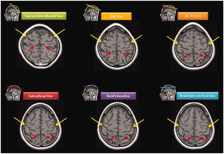
According to the original meaning of the word, the angle of “axial” MR images is vertical to the bed of the equipment. However, with the development of oblique imaging in the late 1980s, “axial” has come to mean a range of angles. At the present time, brain axial images are oblique, and six different angles are used. The angle is determined based on each reference line. In order from acute to obtuse, the reference lines are the supraorbito-meatal line, orbito-meatal (OM) line, anterior commissure (AC)-posterior commissure (PC) line, subcallosal line, Reid’s baseline and the brainstem vertical line (Figure 1).
Figure 1.
The illustration shows the difference of angles of six axial reference lines. In order of the angle from acute to obtuse, the reference lines are: supraorbito-meatal (SM) line, orbito-meatal (OM) line, anterior commissure (AC)-posterior commissure (PC) line, subcallosal (SC) line, Reid’s baseline and brainstem vertical line.
This article is a guide to the six axial angles. We explain the definitions, characteristics, advantages, disadvantages and landmarks needed to determine the angles on the midsagittal image.
Difference of appearance
The images from different angles demonstrate different appearances and relationships of structures. On the images through the orbits, the structures included on the images vary from the spinal cord to the cerebral peduncles (Figure 2). On the images at the parietal region, the locations of the central sulci and pars marginalis move from the anterior to the posterior (Figure 3).
Figure 2.
Six axial images of different angles through the orbits. As the angle is changed, the structures of the posterior fossa range from the spinal cord to the cerebral peduncles.
Figure 3.
Six axial images of different angles at the parietal region. As the angle is changed, the locations of the central sulci (yellow arrows) and pars marginalis (red arrows) gradually move from the anterior to the posterior.
Reference lines
Supraorbito-meatal line
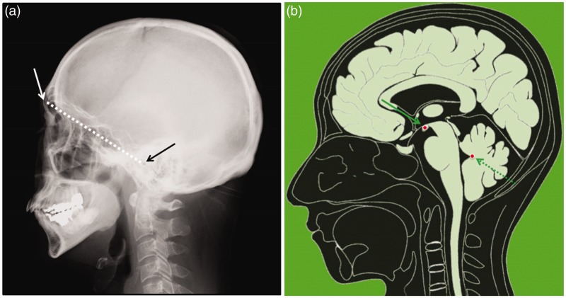
The supraorbito-meatal line passes through the most anterior point of the superior orbital wall and the center of the external auditory meatus (Figure 4).
Figure 4.
(a) The supraorbito-meatal line on a skull X-ray passes through the most anterior point of the superior wall of the orbital cavity (white arrow) and the center of the external auditory meatus (black arrow). (b) The illustration of the midsagittal image shows that the landmarks of the supraorbito-meatal line are the center of the mammillary body (solid arrow) and the fastigium of the fourth ventricle (dotted arrow).
This is the most acute line used on computed tomography (CT). The most inferior slice is set at the superior portion of the orbital cavity. This slice does not include the orbit; therefore, it is useful for avoiding irradiation.1,2 This line has been routinely used in some institutions.3 MR examination does not use X-rays; therefore, irradiation to the orbit is unrelated. Thus, this line is rarely used in MR examination.
The landmarks to determine the angle on the midsagittal MR image are the center of the mammillary body and the fastigium of the fourth ventricle.4
OM line
The OM line passes through the outer canthus and the center of the external auditory meatus (Figure 5).
Figure 5.
(a) The orbito-meatal (OM) line (dotted arrow) is used for positioning of Waters’ view (solid arrow). The angle from the OM line is 45 degrees. (b) The illustration of the midsagittal image shows that the landmarks are the center of the mammillary body (solid arrow) and the most posterior point of the cerebellar tentorium (dotted arrow). (c) On the axial image obtained by using these landmarks, the lens (arrow) and the external auditory meatus (arrowhead) are shown.
This line is frequently used as the positioning line for skull X-ray. It is necessary as the reference line for an anterior-posterior (AP) view, the Waters method (for the maxillary sinus), Rhese method (for the optic canal), Towne method (for the posterior fossa), Stenvers method (for the auditory ossicle) and others. In CT imaging, this line is standard. It is set by tilting the gantry using the guiding light beam that runs through the outer canthus and the center of the external auditory meatus. With a relatively small number of slices, it covers the whole brain. By using this line in MR examination, the same anatomy is obtained as via CT. However, this line is not popular compared to the AC-PC line.
The landmarks to determine the angle on the midsagittal MR image are the center of the mammillary body and the most posterior point of the cerebellar tentorium.4
AC-PC line
The AC-PC line is most commonly used in brain axial imaging. There are several kinds of AC-PC lines.5 Among them, the Talairach AC-PC line and the Schaltenbrand AC-PC line are commonly used. The Talairach AC-PC line passes through the superior edge of the AC and the inferior edge of the PC. The Schaltenbrand AC-PC line passes through the center of the AC and the center of the PC (Figure 6).
Figure 6.
(a) The midsagittal MR image shows the AC (solid arrow) and PC (dotted arrow). (b) Among several kinds of the AC-PC lines, the Talairach AC-PC line and the Schaltenbrand AC-PC line are commonly used especially for stereotaxic surgery. The Talairach AC-PC line passes through the superior edge of the AC and the inferior edge of the PC (solid line). The Schaltenbrand AC-PC line passes through the center of the AC and the center of the PC (dotted line). (c) The illustration of the midsagittal image shows the AC (solid arrow) and PC (dotted arrow). For the Talairach AC-PC line, the landmarks are the superior edge of the AC and the inferior edge of the PC. For the Schaltenbrand AC-PC line, the landmarks are the center of the AC and the center of the PC.
AC: anterior commissure; MR: magnetic resonance; PC: posterior commissure.
In 1988, Talairach and Tournoux published their “Co-planar stereotaxic atlas of the human brain.” They defined the intercommissural basal brain line as passing through the superior edge of the AC and the inferior edge of the PC.6 Since then, the Talairach AC-PC line has been essential for stereotaxic surgery and functional brain studies, and also for the coordinate system. In 1959, Schaltenbrand proposed the line that passes through the center of the AC and the center of the PC.7 The Schaltenbrand AC-PC line is also used because the superior edge of the AC and the inferior edge of the PC are difficult to identify on the midsagittal image.8
For the Talairach AC-PC line, the landmarks to determine the angle on the midsagittal MR image are the superior edge of the AC and the inferior edge of the PC. For the Schaltenbrand AC-PC line, the landmarks are the center of the AC and the center of the PC. Both the AC and PC are small structures; therefore, they are not easily identified on the low-quality localizer image. Sagittal images generally need to be obtained before axial imaging.
Subcallosal line
The subcallosal line passes through the inferior border of the genu and the inferior border of the splenium of the corpus callosum (Figure 7).
Figure 7.
(a) The locations of the rostrum, genu and splenium of the corpus callosum are shown. (b) The illustration of the midsagittal image shows that the landmarks of the subcallosal line are the inferior border of the genu (solid arrow) and the inferior border of the splenium of the corpus callosum (dotted arrow).
This line was developed in the era of MR examination. The corpus callosum is a large structure on the midsagittal image; therefore, it is easy to determine this reference line. This line is recommended in the guidelines for the diagnosis and follow-up of multiple sclerosis.9,10 This line is more obtuse than the AC-PC line. This line is rarely used in CT, so it cannot be compared with CT.
The landmarks to determine the angle on the midsagittal MR image are the inferior border of the genu and the inferior border of the splenium of the corpus callosum.
Reid’s baseline
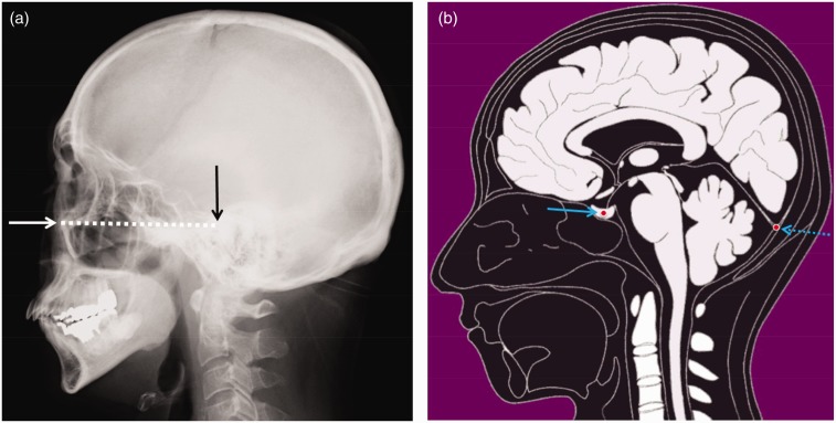
Reid’s baseline passes through the inferior border of the orbital cavity and the superior border of the external auditory meatus (Figure 8).
Figure 8.
(a) Reid’s baseline on a skull X-ray passes through the inferior border of the orbital cavity (white arrow) and the superior border of the external auditory meatus (black arrow). (b) The illustration of the midsagittal images shows that the landmarks of Reid’s baseline are the center of the pituitary gland (solid arrow) and the most posterior point of the cerebellar tentorium (dotted arrow).
This line has been used as the standard horizontal line of the skull when humans stand upright and face forward. The name derives from the Scottish anatomist Robert W. Reid (1851–1939). This line was originally defined as the line drawn from the inferior border of the orbital cavity to the center of the external acoustic meatus. In 1884, it was established at the World Congress on Anthropology in Frankfurt, Germany. Therefore, it is also called the “Frankfurt plane” or “horizontal plane of Germany.” In 1962, the World Federation of Radiology redefined it as the line drawn from the inferior border of the orbital cavity to the superior border of the external auditory meatus. This line has been used for diagnosis of lesions in the orbital cavity, paranasal cavity and skull base.11 Coronal CT scans perpendicular to this line are useful for evaluating the ostiomeatal complex and are essential for endoscopic sinus surgery.12 Comparison with CT is easily performed when CT is obtained with this line.
The landmarks to determine the angle on the midsagittal MR image are the center of the pituitary gland and the most posterior point of the cerebellar tentorium.4
Brainstem vertical line
The brainstem vertical line is perpendicular to the brainstem (Figure 9).
Figure 9.
(a) The illustration of the midsagittal image shows that the landmark of the brainstem vertical line is the perpendicular line (blue dotted line) to the posterior border of the brainstem (red dotted line). (b) The slice parallel to the anterior commissure-posterior commissure line (dotted line) includes both the pons (*) and the medulla oblongata (**). Therefore, the diagnosis about the location of a lesion tends to be misunderstood.
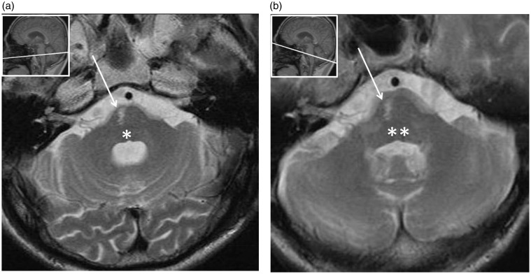
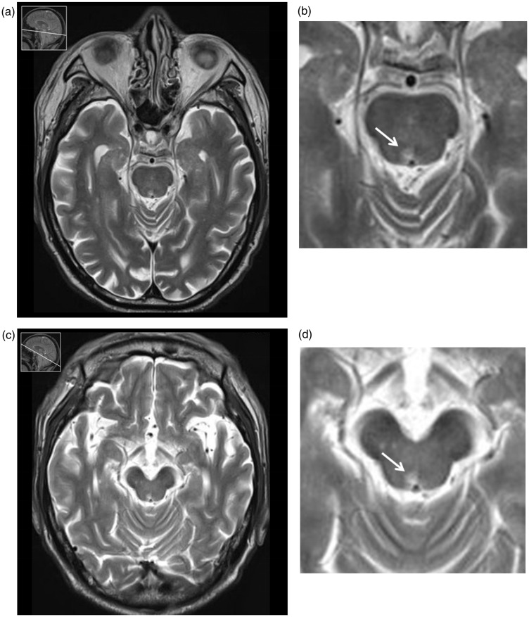
This line was developed in the era of MR examination. This angle is useful for evaluating the brainstem in detail.13 On other axial angles, including AC-PC, the medulla oblongata appears posterior to the pons. Therefore, diagnosis concerning the location of a lesion tends to be misunderstood (Figure 10 and 11). When this line is used, the pons and the medulla oblongata do not appear on the same axial image. This line is not useful for the supratentorial region.
Figure 10.
A 72-year-old male presented with pontine ventral infarction. (a) On the T2-weighted brainstem vertical plane, it is clear that the lesion is at the level of the pons (*). (b) On the T2-weighted anterior commissure-posterior commissure plane, the lesion might be misinterpreted to be at the level of the medulla oblongata (**).
Figure 11.
A 79-year-old male presented with medial longitudinal fasciculus (MLF) syndrome due to upper pontine tegmental infarction. (a) T2-weighted brainstem vertical plane at the level of the upper pons. (b) The lesion is shown at the level of the upper pons; therefore, MLF syndrome can be diagnosed. (c) T2-weighted anterior commissure-posterior commissure plane at the level of the cerebral peduncles. (d) The lesion is shown at the level of the midbrain; therefore, the diagnosis of MLF syndrome might be difficult.
The landmark to determine the angle on the midsagittal MR image is the line perpendicular to the posterior border of the brainstem.
Discussion
Images with various angles can be extracted from brain 3D data. The plane of the angle of the sagittal image is parallel to the interhemispheric fissure. The angle of the coronal image is usually parallel to the bed of the MR equipment or parallel to the brainstem. However, there are six angles for the axial image. This is because axial imaging has a long history since the CT era. The supraorbito-meatal line has been proposed to avoid irradiation to the orbit.1,2 Reid’s baseline has been proposed for orbital and paranasal lesions.11,12
On CT, the OM line is the standard reference line. In emergency cases, CT is often performed due to its short examination time compared to that of MR examination. Also, it is convenient to examine the body and the brain at the same time. When CT demonstrates an abnormality and follow-up MR examination is performed, axial MR images parallel to the OM line enable correlation with CT. In cases that need long-term follow-up and have alternating CT and MR examination, the OM line is recommended for axial MR imaging. For the coordinate system, the AC-PC is a general reference line; however, there have been attempts to use the OM line for it.14
We have presented several landmarks of the midsagittal image. The corpus callosum is a large structure and can be identified even on a low-resolution localizer image; therefore, the subcallosal line can be easily determined. The brainstem is also a large structure on the midsagittal image; therefore, the brainstem vertical line can be easily determined. Although the pituitary gland, mammillary body, fourth ventricle and cerebellar tentorium are not large structures, these landmarks can be identified on the midsagittal image. Therefore, the supraorbito-meatal line, the OM line and Reid’s baseline can be determined relatively easily.
Among the six axial reference lines, the AC-PC line is the most commonly used. This angle has been essential for stereotaxic surgery in particular. Among the several kinds of AC-PC lines, the Talairach AC-PC line and the Schaltenbrand AC-PC line are commonly used. The Talairach AC-PC line passes through the superior edge of the AC and the inferior edge of the PC.6 The Schaltenbrand AC-PC line passes through the center of the AC and the center of the PC.7 However, both the AC and PC are small structures, so these are sometimes unclear on the localizer image. In such cases, sagittal images have to be obtained for clear demonstration of the AC and PC. On 3D MR imaging, such preparation is unnecessary because clear sagittal images can be extracted from the 3D data. Therefore, the AC-PC line can be used more often. As we have demonstrated, each of the six angles has advantages. Radiologists should know their characteristics and select the optimal angle for making a correct diagnosis.
Conflict of interest
The authors declared no potential conflicts of interest with respect to the research, authorship and/or publication of this article.
References
- 1.Lund E, Halaburt H. Irradiation dose to the lens of the eye during CT of the head. Neuroradiology 1982; 22: 181–184. [DOI] [PubMed] [Google Scholar]
- 2.Yeoman LJ, Howarth L, Britten A, et al. Gantry angulation in brain CT: Dosage implications, effect on posterior fossa artifacts, and current international practice. Radiology 1992; 184: 113–116. [DOI] [PubMed] [Google Scholar]
- 3.Smith AN, Shah GA. A survey of routine head CT protocols in Australia. Br J Radiol 1997; 70: 372–374. [DOI] [PubMed] [Google Scholar]
- 4.Otake S, Yamana D, Mizutani H, et al. Reference lines for oblique axial MR imaging of the brain. Radiology 1996; 198: 906–907. [DOI] [PubMed] [Google Scholar]
- 5.Nowinski WL. Modified Talairach landmarks. Acta Neurochir 2001; 143: 1045–1057. [DOI] [PubMed] [Google Scholar]
- 6.Talairach J, Tournoux P. Co-planar stereotaxic atlas of the human brain, New York: Thieme, 1988, pp. 1. [Google Scholar]
- 7.Schaltenbrand G and Wahren W. Atlas for stereotaxy of the human brain. 2nd ed. Stuttgart: Thieme, 2005, pp.50–55.
- 8.Choi SH, Chi JG, Kim YB, et al. Anterior commissure-posterior commissure revisited. Korean J Radiol 2013; 14: 653–661. [DOI] [PMC free article] [PubMed] [Google Scholar]
- 9.Simon JH, Li D, Traboulsee A, et al. Standardized MR imaging protocol for multiple sclerosis: Consortium of MS centers consensus guidelines. AJNR Am J Neuroradiol 2006; 27: 455–461. [PMC free article] [PubMed] [Google Scholar]
- 10.Traboulsee A, Simon JH, Stone L, et al. Revised recommendations of the consortium of MS centers task force for a standardized MRI protocol and clinical guidelines for the diagnosis and follow-up of multiple sclerosis. AJNR Am J Neuroradiol 2016; 37: 394–401. [DOI] [PMC free article] [PubMed] [Google Scholar]
- 11.Honda H, Watanabe K, Kusumoto S, et al. Optimal positioning for CT examinations of the skull base: Experimental and clinical studies. Eur J Radiol 1987; 7: 225–228. [PubMed] [Google Scholar]
- 12.Yousem DM. Imaging of sinonasal inflammatory disease. Radiology 1993; 188: 303–314. [DOI] [PubMed] [Google Scholar]
- 13.Nakagawa H, Iwasaki S, Kichikawa K, et al. Normal myelination of anatomic nerve fiber bundles: MR analysis. AJNR Am J Neuroradiol 1998; 19: 1129–1136. [PMC free article] [PubMed] [Google Scholar]
- 14.Sandor T, Tieman J, Ong HT, et al. Comparison of the precision of two standardized co-ordinate systems for the quantitation of brain anatomy: Preliminary results. Neuroradiology 1994; 36: 499–503. [DOI] [PubMed] [Google Scholar]


