Abstract
Significance
Acquired monocular vision (AMV) is a common visual field loss. Patients report mobility difficulties in walking due to collisions with objects or other pedestrians on the blind side.
Purpose
The visual field of people with AMV extends to over 90° temporally on the side of the seeing eye but is restricted to about 55° nasally. We developed a novel field expansion device, using a multiplexing prism (MxP) that superimposes the see-through and shifted views for true field expansion without apical scotoma). We present various designs of the device that enable individual fitting and improved cosmetics.
Methods
A partial MxP segment is attached (base-in) near to the nose bridge. To avoid total internal reflection due to the high angle of incidence (55°) at nasal field end, we fit the MxP with serrations facing the eye and tilt the prism base toward the nose. The width of the MxP (the apex location) needed to prevent apical scotoma and monocular diplopia is calculated. We also consider the effect of spectacle prescriptions on these settings. The results are verified perimetrically.
Results
We documented the effectivity of various prototype glasses designs with perimetric measurements. With the prototypes, all patients with AMV had field of view expansions up to 90° nasally without any loss of seeing field.
Conclusions
The novel, properly mounted, MxP in glasses have the potential for meaningful field of view expansion up to the size of normal binocular vision in cosmetically acceptable form.
Keywords: field expansion, visual field loss, monocular vision, prism, vision rehabilitation, multiplexing
Acquired monocular vision due to the loss of an eye is frequently caused by injury and is not rare. It has been estimated that 50,000 people lose an eye each year in the United States,1 while the annual incidence of enucleation is 4.3 per 100,000 people.2 About 2% of private ophthalmic patients from total 21,0003 was reported as acquired monocular vision. Complete loss of sight of one eye due to accidents, poisonings, and violence is common,3 disease such as advanced glaucoma, optic neuropathies, proliferative diabetic retinopathy, intraocular tumors, choroidal hemorrhage, endophthalmitis, or chronic uveitis also cause acquired monocular vision.4, 5 We found no estimated frequency of complete loss of vision in one eye without the enucleation of the eye. Acquired monocular vision results in loss of stereoscopic binocular vision, but numerous monocular depth cues may provide adequate depth perception in many situations and compensate for the loss after a period of adaptation.1 On the other hand, the field loss of ~30° (temporal crescent) on the side of the non-seeing eye is persistent. Patients with monocular peripheral field loss with residual central field and a healthy fellow eye also have difficulties in mobility due to the loss of peripheral field (monocular temporal crescent). Note that the blind side of acquired monocular vision in this paper indicates the nasal side of the seeing eye, in a case of one blind eye, it is the side (left or right) of the blind eye.
The visual field of people with acquired monocular vision extends to over 90° temporally with the seeing eye but is restricted to about 55° nasally.6 People with acquired monocular vision have reported various difficulties with mobility.4 Although most jurisdictions do not impose restrictions on driving with monocular vision (except for a period of adaptation), 39% of previous drivers in a study of people with acquired monocular vision4 stated that their driving was negatively affected. When walking, frequently bumping into other people and cutting them off has also been reported.1,4 Crowded environments such as shopping centers, bus terminals, and busy city streets are the most problematic, and patients often have spouses or friends walk on the blind side to prevent collisions, or on their seeing side to maintain continuous visual contact with companions.7 Half of the people with acquired monocular vision in the study of Codey et al.4 reported a negative impact on their ability to pursue various hobbies and play sports.
An acquired monocular vision rehabilitation program was developed at the Buffalo Veterans Affairs Medical Center VISOR clinic in an effort to address the needs of these patients.5, 8 However, there are only a few specific and effective devices and treatment options that can be offered in these programs. Self-help books published by people with acquired monocular vision also describe difficulties experienced due to the field loss.1, 9
People with acquired monocular vision are commonly advised to turn their head toward the blind side while keeping their seeing eye looking straight.4,10,11 This may provide about 8° of visual field expansion (out to about 63°6) by using the part of the visual field blocked by the nose when in the primary position of gaze, where the patient is likely to be looking most of the time when walking.12,13 Turning the head farther cannot provide more field expansion because the retina is not functional on its far temporal side. Furthermore, temporal orbital structures could then block temporal field of view on the seeing side.6,14 In addition, it is very difficult to maintain this posture, which may cause neck pain or eye discomfort.6
People with acquired monocular vision may shift their gaze into the blind side from time to time through head scanning (turning the head while the eyes remain centered in the orbit). During such gaze shifts, the patients can see farther to the blind side by approximately the amount of the gaze shift. However, this gaze shift is merely field substitution with a concurrent loss of the temporal field on the seeing side.14 Since the person with acquired monocular vision will not know when an impeding hazard is approaching, there is no clear indication of when to perform these scans. Such gaze shift is difficult in mobility, as it interferes with foveal monitoring of the path ahead. No significant difference in the number of head movements was found between normal and acquired monocular vision tractor-trailer drivers.15 Note that eye scanning (eye rotation without head rotation) into the blind side results in further loss of nasal field due to the field blocked by the nose and nose bridge.6 The latter effect is due to the location of the center of rotation of the eye, about 10 mm behind the entrance pupil.16 A dramatic approach to address this limitation might be to remove the nose bridge surgically.17 A 15th-century Italian warrior, Duke Federico da Montefeltro, who lost an eye in a battle tried this approach (https://en.wikipedia.org/wiki/Federico_da_Montefeltro) and might have gained a small expansion of the visual field when in the primary position of gaze.
In addition to head turning and eye or gaze scanning, several approaches have been proposed to expand the field-of-view in acquired monocular vision, specifically, using optical devices such as mirrors and prisms. In reviewing these approaches, we distinguish field of view (the portions of the scene that fall on functional retina, whether through an optical device or outside of the device) from the visual field (the functional retinas).18 We also distinguish field expansion from field substitution.19 Certain optical devices bring some of the field of view on the blind side into view, but lose a similar portion of the field of view on the seeing side20 or elsewhere (e.g., at an apical scotoma19). In such cases, even though the patient may see farther into the blind side, the total size of the field of view remains about the same as the size of the visual field without the device, and the effect of the devices is considered field substitution, not field expansion. A field expansion device should provide a meaningfully larger field of view into the blind side compared to the visual field without the device.
Ihrig5, 8 suggested the use of a small mirror (~3 inches in diameter; at arm’s length ≈ 10°) mounted on a walking cane, bicycle handle bar, or on the windshield of a car within the visual field of the seeing eye. With an appropriate tilt of the mirror, a person with acquired monocular vision can see a small portion of the blind side in the reflected scene. A mirror of that sort operates like the rear or side view mirrors in cars, which reflect the rear view rather than a portion of the peripheral side view from the missing temporal crescent. The mirror size would have to be much larger to bring a wider field of view into the blind side, but a larger mirror would also block a larger portion of the scene behind the mirror, thereby substituting part of the field of view on the seeing side with that of the mirror view. The mirror also results in a reversal of objects and direction of motion. The image reversal is not difficult to comprehend in a rear view but may be confusing for a side view.
Prisms have been used for field expansion in various conditions, particularly for homonymous hemianopia19–24 and concentric peripheral field loss.18, 25 The various prism designs for field expansion shift the scene from the blind side (prism base side) to the seeing side, without reversal of the image or direction of motion.
However, the apical scotoma that occurs at the apex of any prism prevents detection of collision or hazards within that region, which limits the utility of prisms as field expansion devices.19 The size of the apical scotoma is the same magnitude as the effective prism power at the apex, which varies with the angle of incidence, and thus the apical scotoma is wider with either a higher prism power or higher angle of incidence.26 The apical scotoma limitation has been overcome in some field expansion designs (for patients with functional vision in both eyes) by fitting the prism only on one eye, which allows the other eye to see the part of the field of view blocked by the prism (i.e., unilateral fitting of a binocular patient).19, 22 This approach, however, is not available for people with acquired monocular vision.
A prism at the high angle of incidence at the far nasal periphery for acquired monocular vision may also be affected by total internal reflection.26 High power prisms are likely to encounter total internal reflection with even small angles of incidence toward the base. Total internal reflection limits the range of field expansion, the benefit of eye scanning, and may completely block the prism shift needed for field expansion.24, 26
We recently introduced a novel optical element, the multiplexing prism (MxP), which eliminates the apical scotoma and thus enables prismatic field expansion (not field substitution) for acquired monocular vision patients.17, 27 The multiplexing prism is a modified Fresnel prism which has alternating small prism and flat segments, providing a shifted view for field expansion and a superimposed see-through view to overcome the apical scotoma. However, total internal reflection remained as a limitation for field expansion at higher eccentricities even with the multiplexing prism (as in Fig. 5 in Peli and Jung17).
In this paper, we present novel designs and implementations to overcome total internal reflection and maximize field expansion for acquired monocular vision using multiplexing prism segments that eliminate the apical scotoma. Our designs further consider and address the expected range of eye scanning during mobility, (Vargas-Martin et al. IOVS 2002;43:ARVO E-abstract 3809)12,13,28 and the impact of spectacle prescriptions on field expansion.
METHODS
We first analyze the requirements for field expansion of acquired monocular vision when the residual emmetropic eye is at the primary position of gaze (Sections 2.1–2.3). In section 2.4, we expand the analyses to consider the impact of eye scanning on the design and use of multiplexing prism -based field expansion. In section 2.5, we incorporate the impact of ametropia spectacle correction on the field and the interactions of these lenses with the multiplexing prism. The field diagrams in the method section are calculated diagrams based on optical analysis to show the theoretical limitation of the device. Measured perimetric results shown in the results section are used to test and verify the theoretical predictions in these diagrams. We call for conducting such verifications to avoid unrealistic and patently wrong results that may be stated without such measurements. All procedures were approved by the Massachusetts Eye and Ear Human Studies Committee in accordance with the Declaration of Helsinki, and all subjects provided informed consent.
Effects of Prism Power and Configuration on Field of View Shift and Total Internal Reflection
For field expansion in acquired monocular vision, the prism should be fitted in a base-in configuration to shift field of view from the nasal blind side to the seeing area. The National Institute for Rehabilitation Engineering (NIRE) developed several designs of prism glasses for acquired monocular vision patients under the name Cros-Vision glasses.29, 30 NIRE proposed the use of low power full-field prisms (3Δ to 8Δ, Type-1 Cros-Vision glasses) for acquired monocular vision field expansion.29, 30 Due to the edge thickness, weight, and poor image quality,31, 32 only low power prisms (<15Δ) have been used in full-field prisms. NIRE implemented a meniscus ophthalmic prism to provide spectacle correction in addition to the prism effect. However, full-field prisms, particularly meniscus ophthalmic prism lenses, cannot provide useful field expansion into the blind side due to the fixation shift induced by the prism as well as limitation from the nose.33 In addition, a full-field prism has an apical scotoma at the temporal edge of the spectacles eyewire.33–35
A partial-field segment of a prism that does not extend to the foveal vision avoids the fixation shift caused by the full-field prisms.33 The mechanical limitations of the ophthalmic prism (edge thickness and weight) can be overcome by using Fresnel prisms. Although the optical quality of the high power Fresnel prism is poorer than that of the corresponding ophthalmic prisms,31,32 a partial-field segment of Fresnel prism located in the nasal periphery may be acceptable, as is the case with peripheral prisms for hemianopia.22,36 The consequences of applying a partial-field segment of base-in, high power Fresnel prism to the nasal edge of the frame must be considered and analyzed in detail, as we do here.
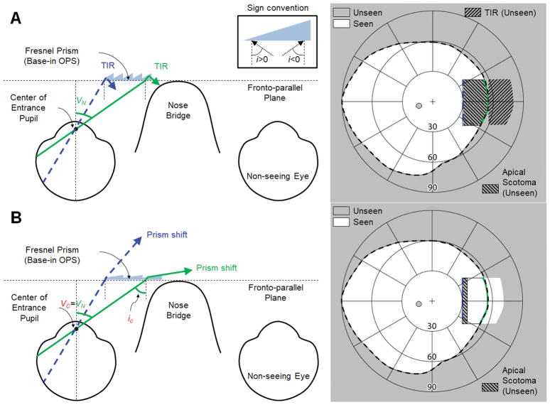
A nasally-fitted, base-in partial segment of high power (57Δ) Fresnel prisms in the outward prism serrations (OPS) configuration26 is shown in Fig. 1A. As the back surface of the prism is parallel to the fronto-parallel plane (with head straight), the angle of incidence is the same as the visual eccentricity. Due to the high angle of incidence toward the base, the rays are reflected inside the prism (total internal reflection) when the incident angle exceeds the critical angle of incidence.26 The field of view through the prism is thus blocked by total internal reflection, and there is no useful shift into the blind side. We use the critical angle of incidence with 50% transmittance (ic, see Appendix, available at [LWW insert link]) in this paper to address meaningful visibility. Therefore, the critical angle of incidence in this paper still results in a visible shifted view with 50% transmittance. In 57Δ outward prism serrations prisms, the nasal field through the prism in Fig. 1A has a higher angle of incidence than iC and is thus blocked by total internal reflection, which results in a net field loss. Note that we only refer to the absolute value of the magnitude of the angle of incidence in the text, and the corresponding sign (see inset in the top of Fig. 1) is only applied in the calculations.
Figure 1.
Partial-field segment of outward prism serrations (OPS) Fresnel prisms (base-in) for left acquired monocular vision. Note that the prisms span the nasal field from 30° to 55° eccentricity (VN). (A) Ray diagram (left) and calculated field diagram (right) with a 57Δ OPS Fresnel prism. There is no prism shift into the blind side due to the total internal reflection (TIR). Note the TIR area in the field diagram marks the expected shifted field if there is no TIR. (B) 7Δ OPS Fresnel prism. This is the maximum prism power possible without TIR (Fig. A1C in Appendix, available at [LWW insert link]). The critical angle of incidence (iC) determines the nasal visual eccentricity where TIR starts (VC). Although the rated prism power as measured at the normal incidence is only 7Δ (8° apex angle in a PMMA prism), the effective prism power increases to ~31Δ (≈ 17° calculated by Eq. A1 in Appendix, available at [LWW insert link]) at the end of the nasal field (VN = 55°), expanding the nasal field of view (FoV) up to 72°. The size of field expansion into the blind side (~17°) is 11° wider than the apical scotoma (~6°), which results in true field expansion. Note the corresponding colors of the rays as marked on the fields on the right.
To avoid the impact of total internal reflection within the seeing field, we could reduce the prism power (smaller apex angle). Since the critical angle of incidence in outward prism serrations prisms is the same as the negative sign of nasal visual eccentricity where total internal reflection starts (VC ≈ -iC), the apex angle would have to be reduced so that the critical angle of incidence is at least as large as the end of the nasal field (VC = VN ≈ 55°), as shown in Fig. 1B. This would achieve true field expansion since the size of the field expansion into the blind side would be wider than the apical scotoma which is also enlarged by the high angle of incidence.
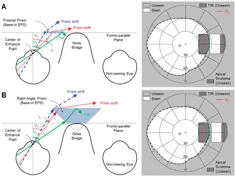
Another way to avoid total internal reflection within the seeing field is to change the prism configuration from outward prism serrations (Fig. 1) to eyeward prism serrations (EPS), Fig. 2, which reduces the angle of incidence by the magnitude of the apex angle (α).17, 26 The nasal visual eccentricity where total internal reflection starts (VC) is defined for the two configurations as follows.
Figure 2.
Partial-field segments of eyeward prism serrations (EPS) fitted base-in for left acquired monocular vision. Note that the prisms span the nasal field from eccentricity 30° to 55° (VN). The critical angle of incidence (iC) determines the nasal visual eccentricity where total internal reflection (TIR) starts (VC). Note the corresponding colors of the rays marked on the fields on the right. (A) 57Δ EPS Fresnel prism. Reduced angle of incidence of the EPS configuration partially avoids TIR, but the field from 44° (VC) to VN is still blocked by TIR. Yet, due to the high effective prism power at VC, up to 82° of the nasal field can be seen (albeit with a minified view). However, the size of the shifted (expanded) field into the blind side is only slightly wider (~4°) than the size of the apical scotoma, resulting in a very small net field expansion while the main effect is field substitution. (B) EPS right angle prism mounted over the nose bridge (Type-2 Cros-Vision30). Despite the higher prism power, TIR starts more centrally (VC ≈ 40°) than in (A) and the expansion of the nasal field of view (FoV) is also limited to 82°. However, with an apical scotoma slightly wider (~2°) than that of the shifted view, the main effect is still field substitution.
| (1) |
For the same power prism, the eyeward prism serrations configuration shifts VC farther nasally by the magnitude of the apex angle compared to the VC in the outward prism serrations configuration.26 In 57Δ prisms (39° apex angle and −5° of ic), for example, the VC is at nasal eccentricities of 5° and 44° for outward prism serrations and eyeward prism serrations, respectively. However, the nasal field beyond 44° in the 57Δ eyeward prism serrations Fresnel prism is still blocked by total internal reflection (Fig. 2A).
The NIRE proposed a related approach, Type-2 Cros-Vision glasses, which used an eyeward prism serrations-like “right angle” prism (45° apex angle) placed over the nose bridge to partially cover the nasal periphery (Fig. 2B).30 Higher prism power (larger apex angle) reduces angles of incidence in the eyeward prism serrations configuration, but the critical angle, iC, is also reduced. In addition, the Type-2 Cross Vision design is cosmetically unappealing and very heavy.30
Tilting the Prism to eliminate Total Internal Reflection Extends the Field of View
To increase the field expansion of the design shown in Fig 2A, we need to move the visual eccentricity where total internal reflection starts (VC) farther nasally so that it begins at or beyond the end of the nasal field (VC ≥ VN). Achieving such a configuration would provide maximum effective prism power at the end of the nasal field, resulting in the widest possible field of view shift into the blind side. Since VC in the eyeward prism serrations prism configuration is determined by the critical angle of incidence (ic) and the apex angle (α in Eq. 1), the angle of incidence should be reduced by the magnitude of VN - VC to eliminate total internal reflection within the seeing nasal field. In addition, the effective prism power is maximized at the critical angle of incidence, thus VC = VN provides maximum field of view shift into the blind side. Both can be achieved by tilting the base of the eyeward prism serrations prism segment toward the nose by the tilt angle (t) determined by Eq. 2.
| (2) |
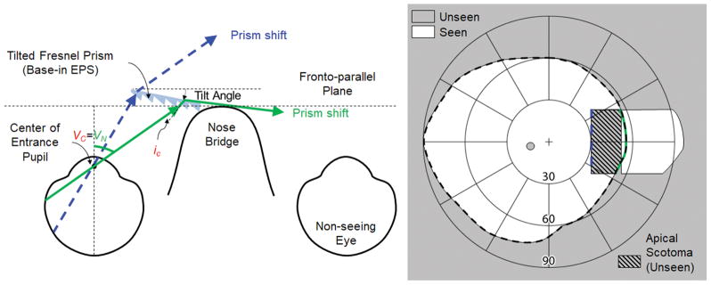
Fig. 3 illustrates the widest prism shift into the blind side without total internal reflection, achieved by a negative face-form tilt37 of the eyeward prism serrations prism segment25. Note, however the large apical scotoma in the near periphery negates much of the benefit of the field expansion.
Figure 3.
Optimized prism field expansion for left acquired monocular vision using a tilted eyeward prism serrations (EPS) Fresnel prism segment to avoid total internal reflection (TIR) within the seeing field. Since the current highest prism power available in Fresnel prisms is 57Δ, an additional 11° tilt of the base of the prism segment toward the eye per Eq. 2 (t =55°-44°=55°-5°-39°) is required to move TIR onset (VC = 44° in Fig. 2A) to the end of the seeing nasal field (55°). This expands the field of view (FoV) into the blind side out to 96°, because the effective deflection power is increased to 87Δ (~41°). With the extended shift of the field larger than the apical scotoma, this configuration results in a small net field expansion.
The tilt of the eyeward prism serrations prism needed to prevent total internal reflection within the seeing nasal field and maximize field expansion varies with prism power (Fig. 4). Higher power prisms require a larger tilt angle, which results in wider field expansion. For safety and cosmetic considerations, relatively lower prism powers that require a smaller tilt angle may be preferred, but with a consquential limitation of the expanded field size. Since the tilt angle to avoid total internal reflection is defined by the difference between VN and VC from Eq. 2, patients with a narrower nasal field (VN) can be fit with a smaller tilt angle. In either case, an optimal tilt can eliminate the impact of total internal reflection, but the apical scotoma continues to limit the effectiveness of field substitution.
Figure 4.
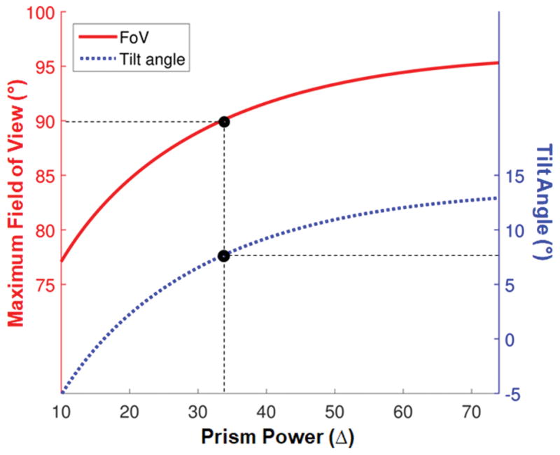
Tilt angle (blue dotted line) required to prevent total internal reflection within the seeing nasal field of 55° and allow for the maximum nasal field of view (FoV) expansion into the blind side (red solid line), as a function of the rated power of eyeward prism serrations (EPS) prisms. For EPS prism configurations, the advantage of the higher power prism with a tilt saturates over 40Δ. Restoring the size of normal visual field (180°) requires a higher than 33Δ prism (with 8° tilt angle) for 90° nasal FoV expansion into the blind side (black marker with dashed lines).
Eliminating the Apical Scotoma Using an Multiplexing Prism
The apical scotoma with conventional Fresnel prisms prevents detection of collisions or hazards in the mid periphery and thus limits the efficacy of the prism field expansion. This can be resolved by replacing the conventional Fresnel prism with our multiplexing prism.17 The multiplexing prism enables true field expansion through the superimposition of the shifted view over the see-through view.17 The use of the multiplexing prism also reduces the impact of spurious reflections in the eyeward prism serrations configuration used here.(see Fig. 5 in Peli and Jung17) The cost of using the multiplexing prism is a 50% reduction of contrast in both the shifted and the see-through views (and, of course, visual confusion). Proper fitting of the tilted eyeward prism serrations multiplexing prism for acquired monocular vision field expansion requires consideration of the effect of horizontal size (width of prism segment) on the apical scotoma, monocular visual confusion, and diplopia between the two views. Similar considerations were applied in the unilateral fitting of Fresnel prisms for homonymous hemianopia.19,26
Double vision (superimposition of two misaligned views), which is commonly experienced binocularly when a prism is placed in front of one eye, is very annoying in central vision, but is tolerable in the peripheral field. With the multiplexing prism design, there is monocular double vision that can include diplopia and visual confusion.38 These two phenomena should be distinguished when considering prism field expansion. Visual confusion (two different objects seen in the same apparent direction) is the underlying principle of prismatic field expansion.19, 38 Diplopia (seeing an object or portion of a scene simultaneously in two different directions) does not contribute to prism field expansion and should be minimized.19,38
In the multiplexing prism, there can be an apical scotoma between the visual eccentricity to the apex, VA, and the apex end of the shifted view. The width of the apical scotoma is equal to the effective prism power at VA (expressed in degrees). To remove the apical scotoma in the multiplexing prism, the width of the see-through view (from VA to VN) should be matched to the width of the apical scotoma. The shifted view from VN is determined by the effective prism power at VN of the tilted eyeward prism serrations v segment. A tilted multiplexing prism segment that extends farther nasally than VC (=VN in this design) is not useful due to total internal reflection, and a segment ending before VN cannot provide the full benefit of the maximum effective prism power. Therefore, only VA (or the width of the prism segment used) can be adjusted to remove the apical scotoma.
Since the two views in an multiplexing prism are angularly separated, we need to consider scotoma or diplopia in three-dimensional space with volume perimetry.39 Previously, volume perimetry was used to consider the volume scotoma (including tunnel scotomas) of binocular central field loss patients, which varies with convergence between the two eyes.40, 41 In the multiplexing prism, a similar volume scotoma can occur between see-through and shifted views, but the angular separation of the two views in the multiplexing prism remains constant with effective prism power (unlike the convergence in binocular central field loss). Therefore, the apical scotoma with the multiplexing prism results in a volume scotoma.
A new concept described here is volume diplopia. In the multiplexing prism, both shifted and see-through views start with angular separation at the base and apex ends. Thus, the three-dimensional area closest to the multiplexing prism segment is always seen twice. However, this area could widen or narrow as a function of distance, depending on the width of the multiplexing prism segments. We call this three-dimensional diplopia “volume diplopia”.
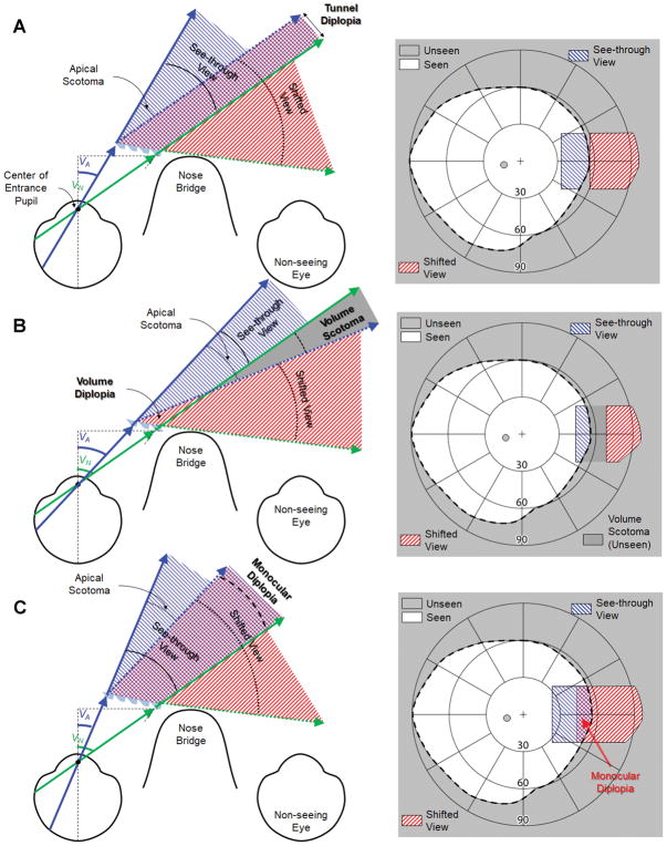
To achieve the optimal width of the tilted eyeward prism serrations multiplexing prism, where neither the apical scotoma19 nor monocular diplopia42 exist, the apical end of the shifted view should be at the same eccentricity as VN (Fig. 5A). VA should fulfill the relationship in Eq. 3 with the effective prism power, d(iA) from Eq. A1 in the Appendix (available at [LWW insert link]), with the angle of incidence at the apex end (iA = t-VA+α from Eq. 2):
| (3) |
Figure 5.
The impact of the multiplexing prism (MxP) segment width (apex location, VA) on the field of view. Assuming that the location of the MxP base position and the tilt angle were optimally determined based on the end of the nasal field (VN) and considered the total internal reflection (Fig. 4). Depending on the location of the MxP apex (VA), the MxP results in a volume scotoma (with a too short segment) or monocular diplopia (with a too long segment) between the see-through view (solid arrows) and the shifted view (dotted arrows). (A) With an optimal width of the MxP segment, the see-through view is exactly the same width as the apical scotoma (the apex end of the shifted view is parallel to the end of the nasal field), and thus there is no apical scotoma. There is a slight tunnel diplopia that diminishes rapidly with distance. (B) With a shorter MxP segment, there is a gap (volume scotoma) between two views (with small volume diplopia closest to the MxP segment). For practical purposes, this volume scotoma effect is not different from a regular apical scotoma. (C) With a longer MxP segment, there is an overlap (monocular diplopia) between the two views. The crosschecked overlapped area is perceived in two different directions. Note the field expansion in the MxP, except where monocular diplopia or volume scotoma is noted, is provided via monocular confusion.
There is a very small linear (a few millimeters) overlap between the two views (Fig. 5A). We call this diplopia “tunnel diplopia” analogous to the tunnel scotoma defined in perimetry.39 The angular span of this overlapping area shrinks rapidly as distance from the eye increases, and the tunnel diplopia that it represents becomes inconsequential.
If the width of the see-through view (the angular width of the multiplexing prism segment) is smaller than that of the apical scotoma (the apex end of the shifted view is at a visual eccentricity < VN), there will be a gap (not a fully eliminated apical scotoma) between the shifted and see-through views (Fig. 5B). In the three-dimensional space closest to the multiplexing prism segment, the scotoma becomes a very narrow volume diplopia (Fig. 5B), but it is inconsequential for hazard detection. These are volume scotomas and diplopia because the width varies angularly with distance. While it is true that this volume scotoma would be in the blind field without the multiplexing prism, it may prevent detection of hazards that could be detected with a properly designed multiplexing prism and thus should be avoided.
On the other hand, if the width of the see-through view is larger than that of the apical scotoma (the apex end of the shifted view is at a visual eccentricity > VN), there is an overlap between two views (resulting in monocular diplopia; Fig. 5C). The monocular diplopia may make the object direction ambiguous and be bothersome for the patient.
The size and location of the apical scotoma varies with the power of the tilted eyeward prism serrations multiplexing prisms. Fig. 6 shows the optimal width of the multiplexing prism, (from VA to VN), for each rated prism power (from Eq. 3) that eliminates the monocular diplopia and apical scotoma.
Figure 6.
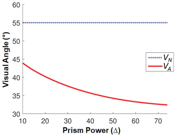
The angular direction of the apex of the multiplexing prism (MxP) segment (VA) that avoids both monocular diplopia and apical scotoma (red solid line). When the base end of see-through view (the end of the nasal field, VN) is fixed at 55° (blue dotted line) and the tilt angle maximizes field of view (FoV) (Fig. 4), VA for higher power MxPs extend more centrally than lower power MxPs. The optimal visual angular width of the MxP as a function of prism power is the distance between the two curves.
With the optimal tilt angle and fit of the multiplexing prism segment determined by the constraints imposed by total internal reflection, monocular diplopia, and apical scotoma, the proposed multiplexing prism glasses for acquired monocular vision should be customized to expand the monocular visual field to cover the nasal blind side, as shown in Fig. 5A. For example, an individual with VN = 55° has an optimal tilt angle of a 57Δ base-in eyeward prism serrations multiplexing prism of 11°(Eq. 2) and VA of 33° in order to satisfy Eq. 3. The see-through view of the multiplexing prism then extends from 33° to 55° (about 12 mm width for a standard back vertex distance of 13 mm19) and the calculated shifted view extends from 55° to 96°, as illustrated with calculated perimetry (Fig. 5A). Using the design considerations of Figs. 3 and 4, there is no total internal reflection, apical scotoma, or diplopia between views when the eye is at the primary position of gaze, where it is expected to be most of the time.
Accounting for Eye Scanning
The design of the multiplexing prism glasses for acquired monocular vision presented above was optimized to maximize the field expansion without monocular diplopia and apical scotoma at the primary position of gaze. This is a reasonable design choice, as the eyes spend most of the time at or near the primary position of gaze when walking.12, 28 Even if patients are trained to scan and subjected to a task that requires scanning, patients tend to revert to primary position of gaze when walking.43 However, the visual field covered by the multiplexing prism segment (VA to VN) varies with eye scanning, which affects the field expansion and may introduce monocular diplopia or an apical scotoma (Fig. 7).
Figure 7.
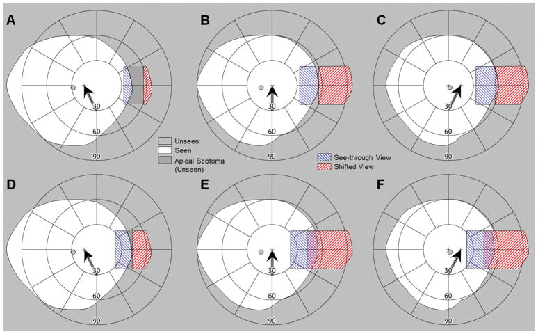
Interaction of eye scanning with the width of the multiplexing prism (MxP) segment. Calculated perimetry diagram in (A–C) no diplopia design and (D–F) no apical scotoma design, for (A&D) 15° eye scanning away from the blind side, (B&E) at primary position of gaze, and (C&F) 15° eye scanning toward the blind side. Head position remains fixed, with the field diagrams centered on the primary position of gaze. The cross marks and the black arrows indicate the fixation target and the direction of the eye scan, respectively; note the corresponding shift of the blind spot. (A–C) When the MxP segment span between eccentricity VA (33°) and VN (55°), there is no monocular diplopia even when the eye scans. However, eye scans away from the blind side (left scanning) result in an apical scotoma that is smaller in width than the magnitude of the eye scans. (D–F) To avoid the apical scotoma caused by eye scans away from the blind side (left scanning), a wider MxP segment (VA = 23°) can be used. Although this eliminates the apical scotoma in (D), it creates monocular diplopia in (E) and (F).
With the size of the tilted eyeward prism serrations multiplexing prism segment optimized for the primary position of gaze in place, eye scanning away from the blind side reduces the visual field covered by the multiplexing prism segment (Fig. 7A). While the apex end of the see-through view (VA) is not changed, the base end of the see-through view is reduced by the eye scanning (smaller than VN). As the nasal edge of the visual field is blocked by the nose as the primary position of gaze becomes usable with eye scanning away from the blind side,6 the amount of reduction in the base end of the see-through view is lower than the amount of the eye scanning. Therefore, the reduced see-through view cannot fully eliminate the apical scotoma. On the other hand, eye scanning toward the blind side does not affect the field expansion (Fig. 7C). The base end of the see-through view is fixed at VN because of the nose. The tilted multiplexing prism segment beyond VN, by design, shows only total internal reflection due to Eq. 2. Therefore, the size of the visual field covered by the multiplexing prism segment and the expanded field are not different from those obtained at the primary position of gaze (Fig. 7B). However, the eye scanning nasally results in a concurrent reduction of the temporal field of view. Note that for simplicity we ignored details of differences between nose bridge, tip and wing and eye movements,6 as these have minimal impact.
To reduce the apical scotoma, wider multiplexing prism segment could be used (Figs. 7D–F). Given that the usual eye scanning range is less than ±15°,12, 13, 28 an multiplexing prism segment that extends ~10° more centrally can prevent the apical scotoma caused by eye scanning away from the blind side (considering a slight nasal visual field that becomes available which was blocked by the nose at the primary position of gaze) (Fig. 7D). However, this would cause monocular diplopia when the eye is at the primary position of gaze (Fig. 7E) and on scanning toward the blind side (Fig. 7F). Note that with this design of the multiplexing prism the impact of the contrast reduction is introduced more centrally at all positions of gaze. Importantly, it gets closer to the fovea on eye scanning toward the blind side (Fig. 7F). With this change, the monocular visual confusion is more central at all positions of gaze. Thus, the main advantage of this design occurs during eye scans toward the seeing side.
Impact of the Prismatic Effects of Spectacle Correction
When the patient uses prescription spectacles to correct for refractive errors, the field expansion prism should be fitted with these lenses. Placing a prism segment behind the lens presents a safety concern, and thus the prism is best fitted in front of the lenses. Spectacle prescriptions have a meaningful prismatic effect, especially at the high eccentricities relevant to the acquired monocular vision case. This effect has to be considered in designing and fitting the multiplexing prism for field expansion of individual patients with acquired monocular vision.
High power prescriptions increase (in myopia, Fig. 8A) or decrease (in hyperopia, Fig. 8B) the extent of the end of the nasal field of view due to the prismatic effect (minification or magnification, respectively). According to Prentice’s rule, the prismatic effect of the eyeglass prescription in degrees (p) is approximately calculated by:
| (4) |
where D is the horizontal power of the spectacle prescription in diopters, and the decentration d in centimeters is a distance from the optical center to the nasal spectacle eye wire, which blocks and defines the end of the nasal field (VN).34, 35 The multiplexing prism fitted in front of the spectacle lenses must be tilted p degrees more for myopia (Fig. 8A) or less for hyperopia (Fig. 8B) to reach the critical angle of incidence at the end of the nasal field (VN + p) corrected by the prescription.
Figure 8.
The impact of spectacle prescription lenses on the multiplexing prism (MxP) field expansion. (A) Effect of myopic correction. The end of the nasal field (solid arrow) is shifted by the prismatic effect (p > 0). To reach the critical angle of incidence at the base end of the corrected nasal field (expanded by the myopic prescription), the MxP segment should be tilted farther than the tilt required without the spectacle correction shown in Fig. 4. The field expansion (dashed arrow) is also wider than the result without correction. (B) Effect of hyperopia prescription. The end of the nasal field is shifted by the prismatic effect centrally (p < 0). The MxP segment should be tilted less, which results in smaller field expansion.
RESULTS
We designed and implemented 4 different types of multiplexing prism glasses for acquired monocular vision field expansion and measured their performance perimetrically each with one patient with acquired monocular vision (total 4 subjects). The multiplexing prism segments were produced (by Chadwick Optical, Souderton, PA) by grinding and polishing flat surfaces onto conventional PMMA Fresnel prism blanks.17 We used multiplexing prisms with 0.5 aperture ratio (the ratio of the area of a prism element to the sum of a prism and a flat element area), same size apertures for the flat and prism elements. The measured visual field without multiplexing prism means the field of view with only prescription glasses. Standard kinetic Goldmann perimetry with V4e stimulus was used. The purpose of the perimetry was only to verify that the theoretical field diagrams based on optical computations were free of errors. The presence of monocular diplopia was determined and marked by asking the subjects to report whenever they saw double stimuli during the perimetry.
Multiplexing Prism Field Expansion Using Wrap-around Glasses
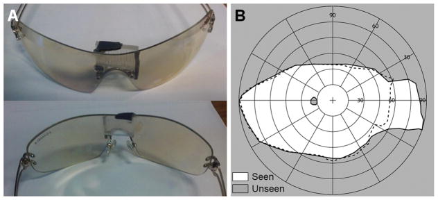
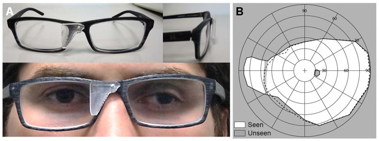
Early prototype multiplexing prism glasses for acquired monocular vision were developed for emmetropic patients. We used wrap-around single lens sunglasses that provided sufficient space behind the lens to fit the tilted eyeward prism serrations multiplexing prism segment near the bridge of the nose (Fig. 9A). The wrap-around glasses offered excellent cosmetics and a wider nasal field (not blocked by a spectacle frame). The tilted 57Δ base-in eyeward prism serrations multiplexing prism segment was held by black plastic mounting supports (Fig. 9A). The prototype multiplexing prism glasses expanded the nasal field of view up to 85° into the blind side without an apical scotoma as shown in Fig. 9B.
Figure 9.
Multiplexing prism (MxP) field expansion glasses for left acquired monocular vision. (A) Front and back views of the 12° tilted 57Δ base-right, eyeward prism serration MxP, for the patient’s 56° nasal field. The prism was attached over the nose bridge inside the wrap-around sunglasses. (B) Goldman perimetry demonstrating field expansion 85° nasally with the MxP without apical scotoma. Dashed lines indicate the visual field measured without the MxP.
Adjustable Multiplexing Prism over Spectacle Correction
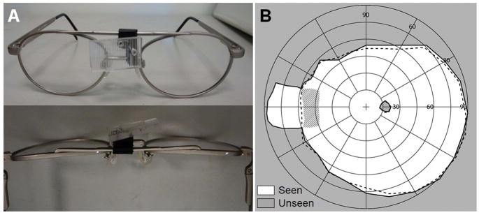
For acquired monocular vision patients who required spectacle correction, we designed a series of different multiplexing prism glasses. We developed prototype glasses with adjustable tilted multiplexing prism supports. The first design modified an adjustable bioptic telescope frame (Ocutech Inc., Chapel Hill, NC), as shown in Fig. 10A. The multiplexing prism mounting support fashioned from the bioptic mounting hardware could slide laterally by releasing a set screw to adjust the apex location (VA) of the multiplexing prism segment to avoid monocular diplopia and apical scotoma.
Figure 10.
Multiplexing prism (MxP) prescription glasses for field expansion of a patient with right acquired monocular vision with sliding MxP segment. (A) Prescription field expansion glasses with a titled MxP segment mounted on a sliding mounting support, shown from the front (top) and from above (bottom). (B) Goldmann field diagram with a tilted 57Δ base-in eyeward prism serration MxP for a 57° corrected nasal field frame (RX −5.00D). The perimetry result shows the field expansion (solid line) to 89° achieved with the MxP glasses, with measured monocular diplopia shown in the hatched area. The dashed line indicates the FoV measured with only the prescription glasses. After sliding the MxP segment nasally to the end of the range, as shown in (A), the monocular diplopia was eliminated with no change in the field expansion.
Fig. 10B shows the field expansion measured with the prototype shown in Fig. 10A for an acquired monocular vision patient who had myopic correction. With the initial position of the multiplexing prism segment, the field of view was expanded to 89° but about 10° of monocular diplopia was found (hatched area in Fig. 10B). The monocular diplopia was fully eliminated by sliding the multiplexing prism nasally, as confirmed with repeated measurements (not shown). The amount of field of view expansion did not change with the lateral shifting of the multiplexing prism.
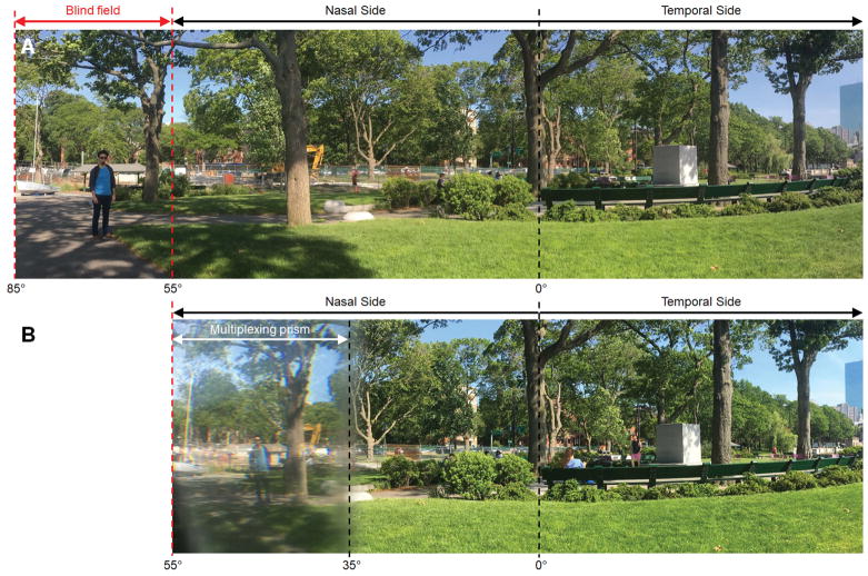
For better cosmetics, we then prototyped fixed multiplexing prism glasses with the segment mounted with a single screw on the nose bridge of plastic frame prescription glasses (Fig. 11A). The prism tilt was tuned using wedge shims between the multiplexing prism and the frame. Fig. 12 shows panoramic scenes captured with and without the multiplexing prism glasses to show the field expansion effect that a user would experience.
Figure 11.
Multiplexing prism (MxP) field expansion glasses for a right acquired monocular vision patient who needed spectacle correction. (A) MxP glasses with the segment fitted on a plastic frame with a narrow nose bridge (16mm). An 11° tilted 57Δ base-in eyeward prism serration MxP was used for the 55° corrected nasal field (measured with −1.25D). The base end of MxP segment was trimmed to fit it to subject’s nose. (B) Goldman field diagram. The dashed line indicates the field of view (FoV) with the prescription spectacles but without the MxP. The FoV was expanded to 84° by the MxP glasses at the primary position of gaze. To reduce the apical scotoma during eye scans away from the blind side (Fig. 13B), we used a slightly larger MxP segment which resulted in a narrow diplopic area at the primary position of gaze (hatched area).
Figure 12.
Panoramic scenes captured (A) without and (B) with multiplexing prism glasses for right acquired monocular vision. The far-left blind field (see a man and a boat between the red dashed lines in A) is visible with the multiplexing prism glasses and is shifted to the seeing nasal field. It is shown through the multiplexing prism as monocular confusion with the see-through view (note the sky around tree crown above the excavator), but not diplopia. Due to the multiplexing prism, the contrast of both parts of the scene is reduced. The camera entrance pupil was located 17 mm from the prism to match the distance between the back surface of the spectacle lens and the entrance pupil of the human eye. The vertical dashed lines indicate horizontal eccentricities, with 0° representing the direction of foveation. The left and right side of the scene are trimmed off.
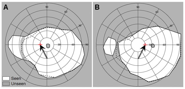
To measure the effect of eye scanning with the multiplexing prism glasses, fixation targets were attached to the perimetry bowl at 15° to the right and left. Fig. 13 shows the field of view with multiplexing prism (solid line) and with only the prescription spectacles (dashed line) with 15° eye turn toward the blind side (Fig. 13A) and toward the seeing side (Fig. 13B).
Figure 13.
The effects of 15° eye shifts toward and away from the blind side with the field expansion glasses of Fig. 11A. The tilted arrows and the red cross marks indicate the fixation of the shifted eye, respectively, which is confirmed by the shift of the mapped physiological blind spot. (A) Goldmann perimetry with gaze shifted 15° (left) toward the blind side. Due to blocking by the nose and the nasal edge of the spectacles eye wire, field expansion to 87° and monocular diplopia (hatched area) are not different from the results at primary position of gaze, but the temporal field is reduced by ~10° due to the gaze shift. (B) Goldmann perimetry with gaze shifted 15° (right) toward the seeing side. This resulted in an apical scotoma, but it was narrower than the size of the gaze shift due to the slightly wider segment used. The field of view is slightly expanded on the temporal right side due to the gaze shift.
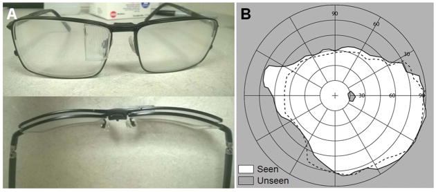
Another option for the multiplexing prism field expansion for acquired monocular vision patients that we explored is the use of a magnetic clip-on multiplexing prism (Fig. 14). The tinted lenses of clip-on sunglasses were replaced with plano lenses. The multiplexing prism was embedded in the lens by cutting an opening on the lens nasal side and gluing the multiplexing prism in place. The subject could use prescription glasses and attach the magnetic clip-on multiplexing prism when needed for mobility. While this was a very convenient format and improved cosmetics, this option limited the tilting angle of the multiplexing prism.
Figure 14.
Magnetic clip-on multiplexing prism (MxP) glasses for field expansion of right acquired monocular vision ametropic patient. (A) Front and top views of the magnetic clip-on MxP mounted on the prescription glasses. Note the natural tilt of the clip-on lens at the position of the MxP. (B) Goldmann perimetry result with and without the magnetic clip-on MxP. The dashed line indicates the visual field without the magnetic clip-on MxP. The MxP clip-on (6° tilted 57Δ base-in EPS MxP) can be effective for users who have narrow nasal field (<50° in this case) as derived from Eq. 2. With the MxP clip-on, the field of view is expanded to about 75°.
DISCUSSION
A base-in eyeward prism serrations multiplexing prism segment fitted nasally with an appropriate tilt of the base side toward the nose provides a true field expansion, rather than field substitution, for people with acquired monocular vision. The use of the multiplexing prism eliminates the apical scotoma and the tilt of the multiplexing prism segment moves the total internal reflection outside the visible range and thus maximizes the field expansion. The proposed methods expand field of view into the blind side at a cost of monocular visual confusion and the consequential contrast reduction. We developed four different prototypes of multiplexing prism glasses and tested that all worked well, but they all have some side effects and limitations to be considered.
The multiplexing prism glasses for acquired monocular vision need to be customized for each patient, considering the parameters that determine VN, such as the back vertex distance, the IPD, the nasal end of eye wire, and the spectacles prescription. Setting and verifying the tilt angle of the multiplexing prism segment from the fronto-parallel plane and locating the multiplexing prism segment at the accurate angular position (VA and VN) are mechanically difficult tasks and prone to measurement errors.
Even if the multiplexing prism on the glasses is manufactured correctly, verification with perimetric measurements is limited by various issues that affect visibility in the far periphery of the shifted view (prismatic distortion and reduced contrast and transmittance).17, 26 Our measurement results with various implementations of multiplexing prism glasses demonstrated field expansion of about 30°, which is about 11° smaller than the expected expansion (41°). The reduced field expansion may have resulted from fabrication errors, especially in implementing the tilt and positioning of the multiplexing prism segment. The field expansion at 90° or more may have been blocked by the frame and lens for the blind eye.
The reduced visibility around the base end may be another cause of the reduced measured field expansion. As shown in Fig. 15, various measures of visibility in the (proximal) apex end and the (distal) base end of the shifted view differ markedly as a result of the different angles of incidence at different visual eccentricities. The effects of magnification factor,26 transmittance, and contrast17 are all worse at the base end of the shifted view than at the apex end. Possible hazards in farther positions appear smaller, dimmer, and at lower contrast. Although we set the critical angle of incidence as the angle of incidence resulting in 50% transmittance in a conventional prism, the multiplexing prism with 0.5 aperture ratio results in an additional 50% reduction of the transmittance.17 As a result, the transmittance of the shifted view at its base end is 25%, while at the apex end of the shifted view has about 45% transmittance. Therefore, the visibility in the farther periphery is worse than the mid-periphery in the multiplexing prism glasses for acquired monocular vision, which is further affected by lower visual sensitivity of peripheral vision.44 The variation of most measures as a function of prism power is small (Fig. 15), with modest variation of magnification (compression) factor at the middle prism powers (10Δ to 30Δ).
Figure 15.
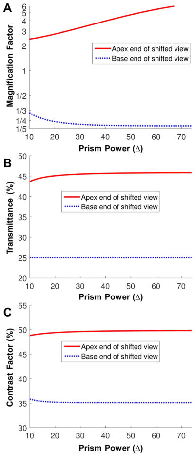
Factors affecting visibility with the tilted MxP at the apex end and the base end of the shifted views as a function of prism rated power. Since the base end of the shifted view is near the critical angle of incidence, the farthest expanded field has the highest compression (minification), lowest transmittance, and lowest contrast. (A) Magnification factor (in log scale). Note that the reciprocal of magnification factor is compression factor. While the base end of the shifted view is compressed (magnification factor < 1), the apex end of the shifted view is actually magnified. (B) Transmittance. Transmittance of the shifted view in an MxP with 1:1 aperture ratio is about 25% at the base end of the shifted view, but it is about 45% at the apex end of the shifted view. (C) Contrast factor.17 Due to the reduced transmittance in the shifted view, the contrast is reduced more at the base end of the shifted view (~35% of the original contrast) than the apex end of the shifted view (~50% of the original contrast).
Using a wider aperture for the prism elements in the multiplexing prism (aperture ratio > 0.5) may increase the visibility in the far periphery, but it would also cause relatively better visibility of the shifted view versus the see-through view at all eccentricities. Alternately, one can develop an multiplexing prism with a different aperture ratio at each eccentricity for uniform contrast, as shown in Fig. 16. An multiplexing prism of that sort could be manufactured in a molding process but not in the grinding of conventional Fresnel prisms we currently use.
Figure 16.
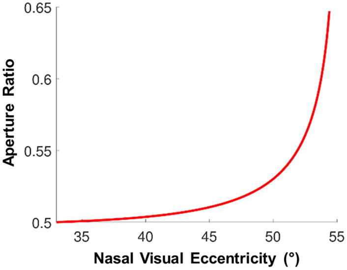
The aperture ratio of 57Δ multiplexing prism (MxP) at each eccentricity required for uniform 50% contrast. If the aperture ratio were constant across the MxP, as eccentricities approach the base (nasal) end contrast of the shifted view would be greatly reduced relative to the see-through view. Increasing the aperture ratio toward the base end, as shown, can maintain a constant contrast ratio at all visual eccentricities.
Frame selection is an important consideration. The nasal field of acquired monocular vision patients is often blocked by the edge of the spectacles eyewire.34, 35 In our perimetry, the end of the nasal field was reduced by 3°–8° by frames. The wrap-around single lens glasses did not block any nasal field, but provided no option for refractive correction, in addition to posing a risk of eye injury from the prism. Since the highest effective prism power is fixed at the critical angle of incidence, a patient with a wider nasal field can see farther into the blind side with the proposed glasses. Therefore, a thinner frame (possibly semi-rimless) with narrower bridge size would be better if there is a way to attach the tilted multiplexing prism segment. We continue to pursue such approaches.
The best way to address the monocular diplopia and apical scotoma during eye scanning remains an open question. Though acquired monocular vision patients are at the primary position of gaze most of the time, the apical scotoma or diplopia may increase the risk of collisions. When we customized the multiplexing prism glasses for one acquired monocular vision patient, we considered this trade-off between monocular diplopia when at the primary position of gaze versus the apical scotoma when eye scanning toward the blind side. The monocular diplopia was not easily noticeable at the far peripheral location in the multiplexed scene and is far less bothersome than central binocular diplopia. On the other hand, the apical scotoma is located around 45° where the risk of the collision with other pedestrians is the highest.45 Therefore, we chose to leave some peripheral diplopia when at the primary position of gaze and reduced the span of the apical scotoma on eye scans toward the multiplexing prism. Although the proposed design involved fairly small tilted multiplexing prism segments, cosmetics remain an issue. The clip-on design could be a partial solution, but there is a limitation on the amount of tilt in this design. A lower power multiplexing prism which requires less tilt (7° tilt angle for 30Δ multiplexing prism) would result in 5° smaller field expansion than a 57Δ multiplexing prism with 11° tilt.
The proposed device is the only true field expansion device for patients with acquired monocular vision as far as we know. All previous devices for acquired monocular vision provide field substitution at best, losing seeing field due to the apical scotoma (or other blocking). Since the multiplexing prism glasses provides a wider field expansion than other devices, the contrast and monocular visual confusion are trade-offs. In future work, we will measure the performance of detection tasks, such as in a driving or walking simulator25, 46, 47 or a mobility course48–50, with the multiplexing prism glasses and compare them to other devices.
Acknowledgments
This work was supported in part by NIH grants R01EY023385 (EP) and P30EY003790 and by Alice Adler Fellowship from Harvard Medical School (JHJ). Dr. Peli has a patent for the Multiplexing Prism and its applications, assigned to the Schepens Eye Research Institute. We thank Chadwick Optical for helping with the manufacturing of multiplexing prisms and attaching them to spectacle frames.
APPENDIX A
The effective prism power (deflection angle from the angle of incidence, d) derived with a refractive index of the prism (n = 1.49 for PMMA) and the apex angle (α) varies with angle of incidence (i) as followed.A1
| (A1) |
The critical angle of incidence (iC,0%) with 0% transmittance is derived with a refractive index of the prism (n = 1.49 for PMMA in this paper) and the apex angle (α) as follow. 1
| (A2) |
Note that we define the angle of incidence directed towards the base, the nasal field, as negativeA1–3 following the sign convention in the inset of Fig. 1A. To address meaningful visibility, we define and use the critical angle of incidence with 50% transmittance (ic) in this paper. This is similar to the definition of the field of view through low vision telescopes.
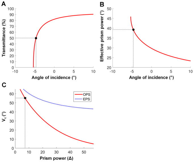
First, we calculate transmittance of the prism in each angle of incidence using Fresnel reflection (Fig. A1A).A4 The angle of incidence resulted in 50% transmittance is calculated which is quite close to the critical angle of incidence with 0% in high power prism. With the calculated ic, the deflection power can be calculated by Eq. A1.
Figure A1.
Critical angle of incidence with 50% transmittance. Note negative sign in angle of incidence is toward the base side. (A) Transmittance and (B) effective prism power vary with angle of incidence in 57Δ prisms. Total internal reflection starts at −5.3° angle of incidence with 0% transmittance and maximizes the effective prism power. However, the transmittance is below 50% with angles of incidence higher than 4.7° toward the base side, which cannot be used for the field expansion due to the low visibility of the shifted view. Therefore, we set the critical angle of incidence for field expansion to −4.7°. At this angle of incidence, the effective prism power is 39° (≈81Δ). (C) Critical angle of incidence with 50% transmittance in various prism powers of OPS and EPS prisms. Dashed line indicates the maximum prism power of OPS prisms without TIR at 55° nasal field (Fig. 1B).
REFERENCES
- A1.Jung JH, Peli E. Impact of High Power and Angle of Incidence on Prism Corrections for Visual Field Loss. Opt Eng. 2014;53:P133. doi: 10.1117/1.OE.53.6.061707. [DOI] [PMC free article] [PubMed] [Google Scholar]
- A2.Peli E, Bowers AR, Keeney K, et al. High-power Prismatic Devices for Oblique Peripheral Prisms. Optom Vis Sci. 2016;93:521–33. doi: 10.1097/OPX.0000000000000820. [DOI] [PMC free article] [PubMed] [Google Scholar]
- A3.Peli E, Jung JH. Multiplexing Prisms for Field Expansion. Optom Vis Sci. 2017;94:817–29. doi: 10.1097/OPX.0000000000001102. [DOI] [PMC free article] [PubMed] [Google Scholar]
- A4.Saleh BEA, Teich MC. Polarization and crystal optics. In: Goodman JW, editor. Fundamentals of Photonics. New York: Wiley; 1991. pp. 192–237. [Google Scholar]
Footnotes
APPENDIX
Critical angle of incidence with 50% transmittance and its effective prism power in various prism powers are analyzed in Appendix A, available at [LWW insert link].
References
- 1.Brady FB. A Singular View: The Art of Seeing with One Eye. 5. Annapolis, MD: Frank B. Brady; 1994. [Google Scholar]
- 2.Erie JC, Nevitt MP, Hodge D, et al. Incidence of Enucleation in a Defined Population. Am J Ophthalmol. 1992;113:138–44. doi: 10.1016/s0002-9394(14)71525-9. [DOI] [PubMed] [Google Scholar]
- 3.Slusher MM, Keeney AH. Monocular Blindness. Sight Saving Rev. 1965;35:207–12. [PubMed] [Google Scholar]
- 4.Coday MP, Warner MA, Jahrling KV, et al. Acquired Monocular Vision: Functional Consequences from the Patient’s Perspective. Ophthal Plast Reconstr Surg. 2002;18:56–63. doi: 10.1097/00002341-200201000-00009. [DOI] [PubMed] [Google Scholar]
- 5.Ihrig C. Vision Rehabilitation Team Management of Acquired Monocular Vision. Optom Vis Sci. 2013;90:e89–e94. doi: 10.1097/OPX.0b013e3182820d74. [DOI] [PubMed] [Google Scholar]
- 6.Good GW, Fogt N, Daum KM, et al. Dynamic Visual Fields of One-eyed Observers. Optometry. 2005;76:285–92. doi: 10.1016/s1529-1839(05)70311-0. [DOI] [PubMed] [Google Scholar]
- 7.Buys N, Lopez J. Experience of Monocular Vision in Australia. J Vis Impair Blind. 2004;98:1–28. [Google Scholar]
- 8.Ihrig C, Schaefer DP. Acquired Monocular Vision Rehabilitation Program. J Rehabil Res Dev. 2007;44:593–8. doi: 10.1682/jrrd.2006.06.0071. [DOI] [PubMed] [Google Scholar]
- 9.Slonim CB, Martino AM. Eye Was There: A Patient’s Guide to Coping with the Loss of an Eye. New York: AuthorHouse; 2011. [Google Scholar]
- 10.Goltz HC, Steinbach MJ, Gallie BL. Head Turn in 1-eyed and Normally Sighted Individuals during Monocular Viewing. Arch Ophthalmol. 1997;115:748–50. doi: 10.1001/archopht.1997.01100150750010. [DOI] [PubMed] [Google Scholar]
- 11.Marotta JJ, Perrot TS, Nicolle D, et al. Adapting to Monocular Vision: Grasping with One Eye. Exp Brain Res. 1995;104:107–14. doi: 10.1007/BF00229860. [DOI] [PubMed] [Google Scholar]
- 12.Bahill AT, Adler D, Stark L. Most Naturally Occurring Human Saccades Have Magnitudes of 15 Degrees or Less. Investigative ophthalmology. 1975;14:468–9. [PubMed] [Google Scholar]
- 13.Luo G, Vargas-Martin F, Peli E. The Role of Peripheral Vision in Saccade Planning: Learning from People with Tunnel Vision. J Vis. 2008;8:1–8. doi: 10.1167/8.14.25. [DOI] [PMC free article] [PubMed] [Google Scholar]
- 14.Kite CR, King JN. A Survey of the Factors Limiting the Visual Fields of Motor Vehicle Drivers in Relation to Minimum Visual Field and Visibility Standards. Br J Physiol Opt. 1961;18:85–107. [PubMed] [Google Scholar]
- 15.McKnight AJ, Shinar D, Hilburn B. The Visual and Driving Performance of Monocular and Binocular Heavy-duty Truck Drivers. Accid Anal Prev. 1991;23:225–37. doi: 10.1016/0001-4575(91)90002-m. [DOI] [PubMed] [Google Scholar]
- 16.Gross H, Blechinger F, Achtner B. Human eye. In: Gross H, editor. Handbook of Optical Systems, vol. 4: Survey of Optical Instruments. Weinheim, Germany: Wiley-VCH Verlag GmBH & Co. KGaA; 2008. pp. 1–45. [Google Scholar]
- 17.Peli E, Jung JH. Multiplexing Prisms for Field Expansion. Optom Vis Sci. 2017;94:817–29. doi: 10.1097/OPX.0000000000001102. [DOI] [PMC free article] [PubMed] [Google Scholar]
- 18.Apfelbaum H, Peli E. Tunnel Vision Prismatic Field Expansion: Challenges and Requirements. Transl Vis Sci Technol. 2015;4(8):1–13. doi: 10.1167/tvst.4.6.8. [DOI] [PMC free article] [PubMed] [Google Scholar]
- 19.Apfelbaum HL, Ross NC, Bowers AB, et al. Considering Apical Scotomas, Confusion, and Diplopia when Prescribing Prisms for Homonymous Hemianopia. Transl Vis Sci Technol. 2013;2(2):1–18. doi: 10.1167/tvst.2.4.2. [DOI] [PMC free article] [PubMed] [Google Scholar]
- 20.Cohen JM. An Overview of Enhancement Techniques for Peripheral Field Loss. J Am Optom Assoc. 1993;64:60–70. [PubMed] [Google Scholar]
- 21.Gottlieb DD. Method of Using a Prism in Lens for the Treatment of Visual Field Loss. 4,779,972 A. US Patent. 1988 Oct 25;
- 22.Peli E. Field Expansion for Homonymous Hemianopia by Optically-Induced Peripheral Exotropia. Optom Vis Sci. 2000;77:453–64. doi: 10.1097/00006324-200009000-00006. [DOI] [PubMed] [Google Scholar]
- 23.Bowers A, Keeney K, Peli E. Randomized Crossover Clinical Trial of Real and Sham Peripheral Prism Glasses for Hemianopia. JAMA Ophthalmol. 2014;132:214–22. doi: 10.1001/jamaophthalmol.2013.5636. [DOI] [PMC free article] [PubMed] [Google Scholar]
- 24.Peli E, Bowers AR, Keeney K, et al. High-Power Prismatic Devices for Oblique Peripheral Prisms. Optom Vis Sci. 2016;93:521–33. doi: 10.1097/OPX.0000000000000820. [DOI] [PMC free article] [PubMed] [Google Scholar]
- 25.Qiu C, Jung JH, Tuccar-Burak M, et al. Measuring the Effects of Prisms on Pedestrian Collision Detection with Peripheral Field Loss. Transl Vis Sci Technol. 2018 doi: 10.1167/tvst.7.5.1. in press. [DOI] [PMC free article] [PubMed] [Google Scholar]
- 26.Jung JH, Peli E. Impact of High Power and Angle of Incidence on Prism Corrections for Visual Field Loss. Opt Eng. 2014;53:P133. doi: 10.1117/1.OE.53.6.061707. [DOI] [PMC free article] [PubMed] [Google Scholar]
- 27.Peli E. Vision Modification Based on a Multiplexing Prism. PCT/US2014/017351. US Patent Application. 2014 Aug 28;
- 28.Vargas-Martin F, Peli E. Eye Movements of Patients with Tunnel Vision while Walking. Invest Ophthalmol Vis Sci. 2006;47:5295–302. doi: 10.1167/iovs.05-1043. [DOI] [PMC free article] [PubMed] [Google Scholar]
- 29.The National Institute for Rehabilitation Engineering. [Accessed: January 30, 2018];Cros-vision Glasses for People Sighted in One Eye. http://www.schepens.harvard.edu/images/stories/nire/nire_cros_vision_glasses.pdf.
- 30.The National Institute for Rehabilitation Engineering. [Accessed: Accessed: January 30, 2018];Vision Aids for People Sighted in One Eye. http://www.schepens.harvard.edu/images/stories/nire/one_eye.pdf.
- 31.Katz M. Visual Acuity through Fresnel, Refractive, and Hybrid Diffractive/Refractive Prisms. Optometry. 2004;75:503–8. doi: 10.1016/s1529-1839(04)70175-x. [DOI] [PubMed] [Google Scholar]
- 32.Katz M. Contrast Sensitivity through Hybrid Diffractive, Fresnel, and Refractive Prisms. Optometry. 2004;75:509–16. doi: 10.1016/s1529-1839(04)70176-1. [DOI] [PubMed] [Google Scholar]
- 33.Jung JH, Peli E. No Useful Field Expansion with Full-Field Prisms. Optom Vis Sci. 2018;95 doi: 10.1097/OPX.0000000000001271. XXX–XX. [DOI] [PMC free article] [PubMed] [Google Scholar]
- 34.Dille JR, Marano JA. The Effects of Spectacle Frames on Field of Vision. Aviat Space Environ Med. 1984;55:957–9. [PubMed] [Google Scholar]
- 35.Steel SE, Mackie SW, Walsh G. Visual Field Defects due to Spectacle Frames: Their Prediction and Relationship to UK Driving Standards. Ophthalmic Physiol Opt. 1996;16:95–100. [PubMed] [Google Scholar]
- 36.Bowers AR, Keeney K, Peli E. Community-Based Trial of a Peripheral Prism Visual Field Expansion Device for Hemianopia. Arch Ophthalmol. 2008;126:657–64. doi: 10.1001/archopht.126.5.657. [DOI] [PMC free article] [PubMed] [Google Scholar]
- 37.Fry GA. Face-form Frames. J Am Optom Assoc. 1978;49:31–8. [PubMed] [Google Scholar]
- 38.Peli E. The Roles and Effects of Diplopia and Visual Confusion in the Treatment of Visual Field Loss. Proc North American Neuro-Ophthalmology Society 43rd Annual Meeting; Washington, DC. 2017; pp. 469–79. [Google Scholar]
- 39.Satgunam P, Apfelbaum HL, Peli E. Volume Perimetry: Measurement in Depth of Visual Field Loss. Optom Vis Sci. 2012;89:E1265–E75. doi: 10.1097/OPX.0b013e3182678df8. [DOI] [PMC free article] [PubMed] [Google Scholar]
- 40.Arditi A. The Adaptive Significance of the Location of the Optic Disk. Perception. 1987;16:649–54. doi: 10.1068/p160649. [DOI] [PubMed] [Google Scholar]
- 41.Arditi A. The Volume Visual Field: A Basis for Functional Perimetry. Clin Vis Sci. 1988;3:173–83. [Google Scholar]
- 42.Fincham EF. Monocular Diplopia. Br J Ophthalmol. 1963;47:705–12. doi: 10.1136/bjo.47.12.705. [DOI] [PMC free article] [PubMed] [Google Scholar]
- 43.Iorizzo DB, Riley ME, Hayhoe M, et al. Differential Impact of Partial Cortical Blindness on Gaze Strategies when Sitting and Walking - An Immersive Virtual Reality Study. Vision Res. 2011;51:1173–84. doi: 10.1016/j.visres.2011.03.006. [DOI] [PMC free article] [PubMed] [Google Scholar]
- 44.Strasburger H, Rentschler I, Jüttner M. Peripheral Vision and Pattern Recognition: A Review. J Vis. 2011;11:1–82. doi: 10.1167/11.5.13. [DOI] [PMC free article] [PubMed] [Google Scholar]
- 45.Peli E, Apfelbaum H, Berson EL, et al. The Risk of Pedestrian Collisions with Peripheral Visual Field Loss. J Vis. 2016;16:1–15. doi: 10.1167/16.15.5. [DOI] [PMC free article] [PubMed] [Google Scholar]
- 46.Bowers AR, Mandel AJ, Goldstein RB, et al. Driving with Hemianopia: I. Detection Performance in a Driving Simulator. Invest Ophthalmol Vis Sci. 2009;50:5137–47. doi: 10.1167/iovs.09-3799. [DOI] [PMC free article] [PubMed] [Google Scholar]
- 47.Houston KE, Peli E, Goldstein RB, et al. Driving with Hemianopia VI: Peripheral Prisms and Perceptual-motor Training Improve Blind-side Detection in a Driving Simulator. Transl Vis Sci Technol. 2018:7. doi: 10.1167/tvst.7.1.5. [DOI] [PMC free article] [PubMed] [Google Scholar]
- 48.Pundlik S, Tomasi M, GL Evaluation of a Portable Collision Warning Device for Patients with Peripheral Vision Loss in an Obstacle Course. Invest Ophthalmol Vis Sci. 2015;56:2571–9. doi: 10.1167/iovs.14-15935. [DOI] [PubMed] [Google Scholar]
- 49.Bowers AR, Luo G, Rensing NM, et al. Evaluation of a Prototype Minified Augmented-view Device for Patients with Impaired Night Vision. Ophthalmic Physiol Opt. 2004;24:296–312. doi: 10.1111/j.1475-1313.2004.00228.x. [DOI] [PubMed] [Google Scholar]
- 50.Peli E, Luo G, Bowers A, et al. Applications of Augmented Vision Head-mounted Systems in Vision Rehabilitation. J Soc Inf Disp. 2007;15:1037–45. doi: 10.1889/1.2825088. [DOI] [PMC free article] [PubMed] [Google Scholar]


