Abstract
Study Design:
Biomechanical finite element model analysis.
Objectives:
Spinal fractures related to ankylosing spondylitis (AS) are often treated by long posterior stabilization. The objective of this study is to develop a finite element model (FEM) for spinal fractures related to AS and to establish a biomechanical foundation for long posterior stabilization of cervicothoracic fractures related to AS.
Methods:
An existing FEM (consisting of 2 separately developed models) including the cervical and thoracic spine were adapted to the conditions of AS (all discs fused, C0-C1 and C1-C2 mobile). A fracture at the level C6-C7 was simulated. Besides a normal spine (no AS, no fracture) and the uninstrumented fractured spine 4 different posterior transpedicular instrumentations were tested. Three loads (1.5g, 3.0g, 4.5g) were applied according to a specific load curve.
Results:
All posterior stabilization methods could normalize the axial stability at the fracture site as measured with gap distance. The maximum stress at the cranial instrumentation end (C3-C4) was slightly greater if every level was instrumented, than in the skipped level model. The skipped level instrumentation achieved similar rotatory stability as the long multilevel instrumentation.
Conclusions:
Skipping instrumentation levels without giving up instrumentation length reduced stresses in the ossified tissue within the range of the instrumentation and did not decrease the stability in a FEM of a cervicothoracic fracture related to AS. Considering the risks associated with every additional screw placed, the skipped level instrumentation has advantages regarding patient safety.
Keywords: spinal fractures, ankylosing spondylitis, finite element model, spinal instrumentation, biomechanics
Introduction
Ankylosing spondylitis (AS) is a rheumatic disease with a prevalence of 2.4 per 1000 in Europe.1 It primarily affects the joints of the axial skeleton with inflammation, and later ossification and ankylosis. End stage of the natural history of the disease is a completely ankylosed vertebral column—the bamboo spine.
Because of the overall stiffness of the ankylosed spine, the long lever arms can cause highly unstable fractures even in minor trauma.2 Thus, the spinal fracture risk of patients with AS is dramatically increased, and associated with greater mortality.3,4 Common complications are spinal cord compression, pneumonia, kyphosis, and nonunion.5 Along with the developments in spinal instrumentation techniques there is a trend toward surgical treatment.6 This often involves long posterior constructs to neutralize the long lever arms cranially and caudally of the fracture.7 Unfortunately, surgical treatment is associated with complications on its own.8 It is therefore remarkable that the biomechanics of posterior instrumentation constructs for spinal fractures related to AS have not been investigated yet.
This study was designed to develop a finite element model of the ankylosed spine and to provide data that can help the clinician and researcher to answer whether minimal implant density in the long instrumentation of spinal fractures related to AS worsens construct stability.
Methods
The Finite Element Human Model
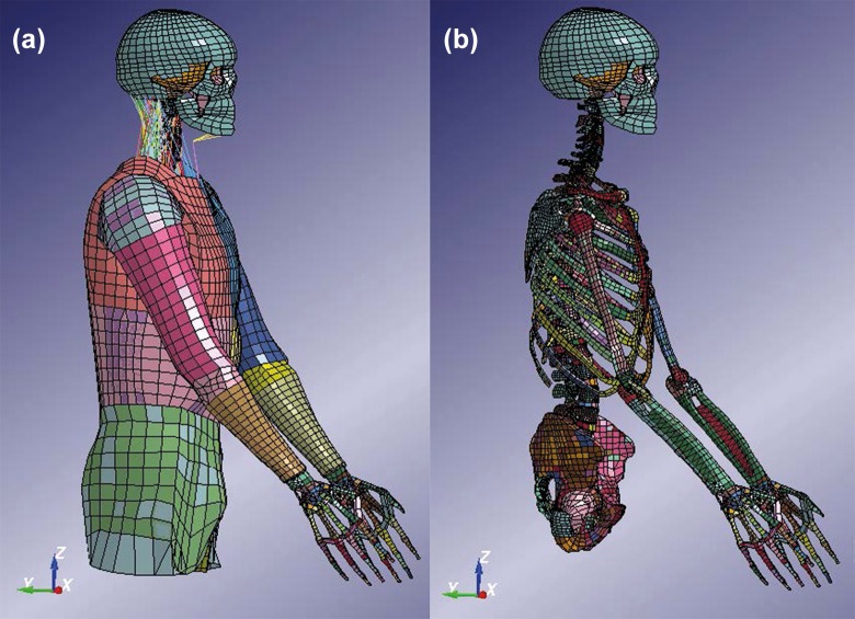
In this study, the combined KTH and THUMS (Total Human Model for Safety) model was used (Figure 1). The head and neck model developed by KTH was used.9 The head and neck model includes the head, vertebrae, ligaments, muscles, and intervertebral discs. The THUMS10 pedestrian model version 1.4 is attached to the KTH neck, where a new disc was modeled at C7-T1 (Figure 2). Only the limbs and the trunk from the first thoracic vertebrae were used for the THUMS model. This combined model has previously been used in study with focus on traffic safety (Figure 3).11 The neck model has been compared to experiments at functional unit levels (both upper and lower vertebrae levels) for different loading mechanisms (flexion, extension, compression, lateral bending, and torsion).9 The head–cervical spine complex has also been compared to experiments in dynamic compression with isolated head-spine complex without muscles.12 Furthermore, it has also been validated for head relative T1 motion in dynamic inertial loading against volunteer sled experiments, including muscle activation in flexion, lateral bending13 and extensions.14
Figure 1.
Full finite element model used for the simulations in this study with (a) and without (b) outer soft tissue parts and muscles. Color coding was used to distinguish the different parts of the model.
Figure 2.
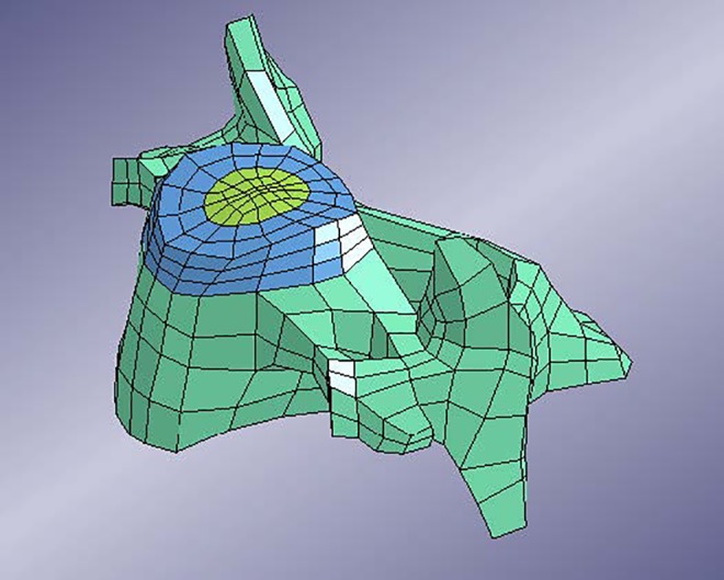
C3 vertebra as it connects to the superior disc.
Figure 3.
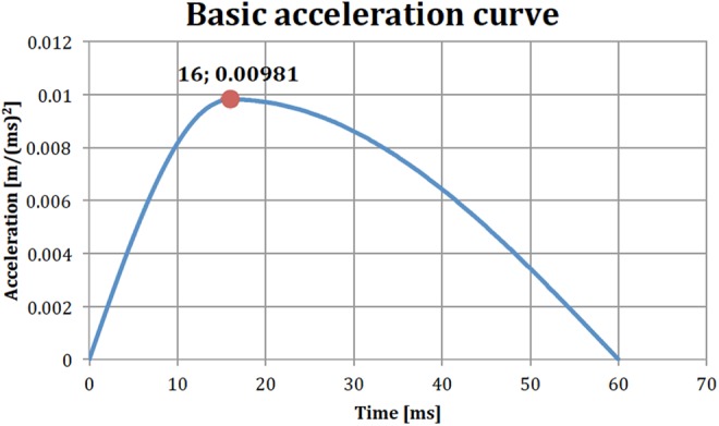
Basic acceleration curve to be multiplied with suitable load factor (acceleration in meters per squared milliseconds).
Software and Hardware
The adaptations of the model to the conditions of AS was performed on LS-PrePost version 3.2 (Livermore, CA, USA) on a Windows 7 system, while the running of the simulations was performed on a Linux machine running CentOS 6.5, using LS-DYNA version R5.1.2 (Livermore, CA, USA).
AS-Spine Adaptation
The spine in late stage AS has following specific features: (1) all discs and all facet joints are fused,15 (2) osteoporosis of the vertebral bodies,16 (3) C0-C1 and C1-C2 are often still mobile,17 (4) thorax and costovertebral ligaments provide passive stability,18 (5) muscles provide active stability,19 and (6) kyphotic deformity of the cervicothoracic region.20
In the model that was used as a foundation for this study, the discs were originally created with rings of shell elements inside solid elements.12 The solid elements represented the bulk material of the annulus fibrosus and the nucleus pulposus. The shell elements represented the fibrous structure of intervertebral discs.
In this study, AS was modeled by giving the outermost ring of shell elements bone tissue properties (see Table 1 for material properties and thickness), while the inner rings were left unchanged. This simulated the disc in ankylosing spondylitis, where the annulus fibrosus is ossified and the central nucleous fibrosus is fibrotically remodeled but still highly mobile.15 In the case of the thoracic and lumbar spines, a new layer of shell elements had to be created at the outer edge of the discs to take into account the ossification.
Table 1.
Disc Ankylosing Spondylitis Ossification Properties.
| Young’s modulus | 10 GPa |
| Poisson’s ratio | 0.2 |
| Density | 5.0 g/cm3 |
| Ossification thickness | 1.0 mm |
The joints between the head and C1 as well as C1 and C2 are not connected with an intervertebral disc. These joints (C0-C1, C1-C2) were left untouched and not considered ossified.
In this version of the model, the vertebrae were considered rigid. Figure 4 shows the intervertebral disc and its different parts: Nucleus pulposus, bulk material of annulus fibrosus, internal fibrous rings of annulus fibrosus and the outer ring (dark blue) that was used for the ossification in the case of AS.
Figure 4.
Intervertebral disc of the model. (a) Nucleus pulposus and bulk material for the annulus fibrosus. (b) Fibrous rings inside of the annulus fibrosus. Blue ring indicates ossified part in the case of ankylosing spondylitis (AS).
Fracture Modeling
The most common level for spinal fractures related to AS is at C6-C7.5,8,21 Therefore, a fracture at C6-C7 was introduced. This was achieved by removing the shell elements representing the ossification at the chosen disc level. This meant that at the C6-C7 disc level there were no remaining elements of the ossification and the vertebrae (C6 and C7) were simply connected by the remaining intervertebral disc elements. It is assumed that a spinal fracture related to AS may bear some load without severe dislocation, which may be true in axial compression loading.
Instrumentation Modeling
The type of instrumentation that was chosen for this study was a system of posteriorly inserted screws connected with rods. In the model, the individual screws and rods were simplified as circular cross-section beam elements. Because beam elements were used, threading of the screws, as well as any detailed screw-rod connection had to be omitted from this model. The screws were modeled with an elastic material model (see Table 2).
Table 2.
Posterior Implant Properties.
| Young’s modulus | 110 GPa |
| Poisson’s ratio | 0.32 |
| Density | 4.4 g/cm3 |
| Screw cross-section diameter | 3.5 mm |
| Rod cross-section diameter | 3.5 mm |
| Total screw length | 35 mm |
| Average distance from screw exit point to rod fixation | 7.0 mm |
Figure 5 shows the idea of connecting 2 sample vertebrae with the beam implant.
Figure 5.
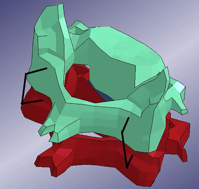
Finite element model of two cervical vertebrae with short segment posterior pedicle screw implant, posterior view.
In the model, a screw consisted of a beam element that passed through the pedicle and the vertebral body. The anterior end of the beam was constrained to a node on the anterior surface of the vertebra. The beam was further constrained to a node on the posterior surface of the vertebra, at its exit point. Thus, each beam representing a screw was constrained to 2 points in the vertebra. The posterior end of the screw was then constrained to the rod. No rotations were allowed at the beams’ ends. Note the 2 screws for each vertebra.
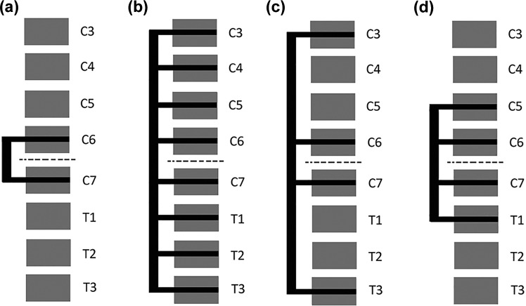
Figure 6 shows a lateral schematic view of the different instrumentation configurations that were chosen for investigation. The first variation, Figure 6a is denoted C6C7. It uses as few vertebral levels as possible, as well as the shortest possible rods. The next variation, Figure 6b, stabilizes C3 to T3, which is the longest instrumentation that was investigated. This is denoted C3toT3. The alternative in Figure 6c has a lesser screw density, while maintaining the same range of the fixation but skipping levels in between. This variation is denoted C3C6C7T3. The last variation (Figure 6d), is denoted C5toT1 and involving vertebrae C5-T1 with screws at every level.
Figure 6.
Schematic lateral views of the different implant configurations. dotted line indicates fractured disc level.
Stability Testing
The chosen loading case for the model was inspired by a mechanical sled acceleration study.22 In that study, healthy subjects where strapped onto a sled to which an acceleration was applied in the sagittal plane. The study aimed at measuring muscle activation. The applied acceleration was described as lasting from 0 to 60 ms with a peak of 1.55g at 16 ms. This data was used to create loading conditions for the model. In the model, the acceleration was applied to the outer surface of the torso and arms, in the anterior direction. The torso was also constrained to allow movement only in the anterior-posterior direction. This was intended to constrain the model as if it was indeed strapped onto the sled in the original study.22 The intention was to create an extension-like movement of the head and cervical spine, since this is considered a common mechanism for injury in AS patients.
The simulations were performed with three different applied accelerations with 3 different peak accelerations: 1.5g, 3.0g, and 4.5g. The shape of the acceleration curve remained the same in the 2 cases with higher acceleration but the acceleration was scaled relative to the original acceleration with a peak of 1.5g. Figure 3 shows the basic shape of the load curve with a peak acceleration of 1.0g at 16 ms. The results were analyzed for the first 300 ms.
Simulations
Table 3 shows the 7 model variations that were used. Each of the 7 models was run for the 3 different loads 1.5g, 3.0g, and 4.5g resulting in a total of 21 simulations.
Table 3.
List of Simulations.
| Model | Figure | Comment |
|---|---|---|
| Normal model | — | The original model, representing a healthy patient with no AS. |
| AS, no fracture | — | Model with elements representing the ossification of parts of the intervertebral discs. This model represents the nonfractured AS patient. |
| AS, fracture (at C6C7 disc level) | — | Model with removed elements in the disc ossification at the C6C7 disc level, representing a fracture. |
| AS, fracture, C6C7 implant | Figure 6a | |
| AS, fracture, C3toT3 implant | Figure 6b | |
| AS, fracture, C3C6C7T3 implant | Figure 6c | |
| AS, fracture, C5toT1 implant | Figure 6d |
Abbreviation: AS, ankylosing spondylitis.
Output Variables
The evaluation of the different implants configurations 4 different outputs were chosen: rigid body rotations of the vertebrae, vertebral gap distance at fracture site, translation of fracture, and stress in the discs ossified parts.
Rigid Body Rotations of the Vertebrae
Since the load is applied in the sagittal plane (anterior-posterior direction,) the rotation of the vertebrae in the sagittal plane was chosen to get an overview of the movements of each individual vertebra. The motion was measured relative to T4, the first vertebra that was not involved in the different implant systems.
Vertebral Gap Distance at Fracture Site
Determining the anterior gap between 2 vertebrae at the fracture site the rigidity of the fracture instrumentation was estimated (Figure 7a). More accurately, the gap distance in the results was defined as the deviation from the original distance between the vertebrae. Therefore, a vertebral gap distance that equaled zero represented the original distance. The gap distance was determined by measuring the distance between a node on the superior part and a node on the inferior part of the disc.
Figure 7.
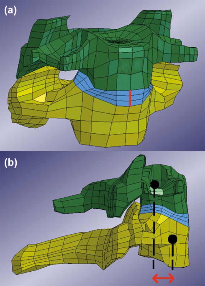
(a) Anterior view of the C6 and C7 vertebrae with disc and the original gap distance marked with thick (red) line. Note that the line represents a gap distance that was set to zero in the results. (b) Lateral view of C6 and C7 vertebra. Arrow (red) indicates measured horizontal translation. Dots should be considered to be in the center of the vertebrae respectively.
Both the gap distance in the anterior as well as the posterior part of the disc were calculated. However, the distance at the anterior part was chosen as the primary concern since it is furthest away from the instrumentation. (The original distance was measured to 5.63 mm in the model.)
Translation of Fracture
Translational mobility of a fractured vertebra in relation to a superior or inferior vertebra is considered a risk factor for spinal cord injury and neurological impairment. Therefore, the shear distance of the C6 and C7 vertebra relative each other—the translation of the vertebrae superior and inferior to the fractured disc—was determined (Figure 7b).
Stress and Stress Shielding in the Discs
The maximum principal stress in the ossified part of the discs were obtained for each disc ossification, respectively, allowing us to measure stresses depending on the different instrumentation configurations.
Results
Spinal Kinematics
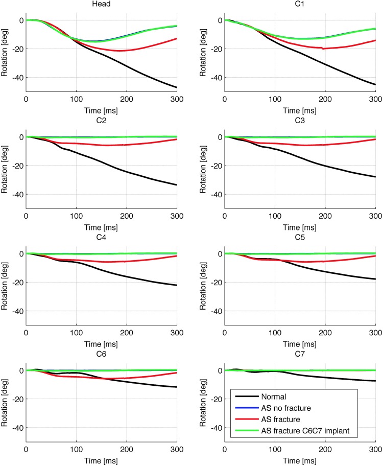
Figure 8 shows the rotations in the sagittal plane of the cranium and C1 to C7 vertebrae for the load 1.5g relative the T4 vertebra. In Figure 8, negative value for rotation corresponded to posterior rotation of the vertebra around its own center of gravity. In other words, the negative value means that the rotation of a given vertebra caused global extension in the spine. The results for the implant configurations other than the C6C7 implant were not included, since they were very similar. Note that the curves representing the nonfracture AS model and the C6C7 implanted model were largely overlapping. Figure 8 demonstrates the typical mobile areas in the case of this fractured AS model: Movement occurred in the head-C1 joint, the C1-C2 joint (which both were left mobile) and at the C6C7 level (where the fracture was located).
Figure 8.
Sagittal plane rotations of head and C1 to C7 vertebrae around their respective centers of gravity for load 1.5g relative to T4. Note that the curve for the implanted model (green) overlaps the “AS No Fracture” curve. AS, ankylosing spondylitis.
Vertebral Gap at Fracture Site
Table 4 shows the maximum vertebral gap at the fracture site occurring during the simulation time. It is shown for all 3 loads and included model variations. Increasing load clearly increased the gap regardless of model variation. Note that there was relatively little difference between the different instrumentations. Also note that the implants allowed some movement, compared to the nonfractured AS model.
Table 4.
Maximum Vertebral Gap Distance (mm) at C6-C7 Depending on Ankylosis, Fracture, Implant, and Acceleration.
| No AS No Fracture | AS No Fracture | AS Fracture | AS Fracture C6C7 Implant | AS Fracture C3C6C7T3 Implant | AS Fracture C3toT3 Implant | AS Fracture C5toT1 Implant | |
|---|---|---|---|---|---|---|---|
| 1.5g | 1.52 | 0.02 | 1.50 | 0.15 | 0.14 | 0.13 | 0.13 |
| 3.0g | 2.99 | 0.05 | 3.35 | 0.59 | 0.55 | 0.51 | 0.52 |
| 4.5g | 4.57 | 0.08 | 3.90 | 1.13 | 1.04 | 1.00 | 0.98 |
Abbreviation: AS, ankylosing spondylitis.
Translation in Fracture
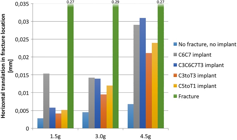
Figure 9 shows the peak value for the horizontal translation at the fracture site, in the transverse plane, for the superior vertebra in relation to the inferior. The translation is shown for all 3 loads and selected model variations. Translation increased with load. The implant that most restricted translation is the C3toT3 instrumentation. Note that for the load 1.5g, the C6C7 implant allowed markedly more movement than the other configurations.
Figure 9.
Maximum horizontal translation in fracture. Ankylosing spondylitis (AS) conditions in all cases.
Maximum Stresses in the Disc Ossifications
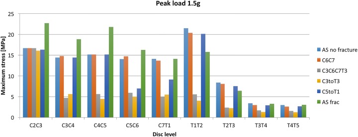
Figure 10 demonstrates the stresses over the investigated spinal segments, indicating the peak value that occurred in the ossified part of the discs during the simulation. The C6C7 disc level was not included since the ossified part was removed to simulate the fracture at that level.
Figure 10.
Peak value of first principal stress in the ossification at different disc levels for load 1.5g.
Consider first the pillar representing the C5toT1 implant: Note that for the C5C6 and C7T1 disc levels, the stresses were reduced compared with the adjacent C4C5 and T1T2 disc levels. The C5C6 and C7T1 levels were inside the range of that specific implant.
A similar stress shielding also occurred for the 2 longer implants (C3toT3 and C3C6C7T3); both ending at C3. The implant shields the disc ossifications that are within the range of the implant. Note also that the stresses for the C2C3 disc levels for these implants are at the same level as the nonfractured AS model. Furthermore, the stresses in the ankylosed discs of the thoracic spine (T2T3, T3T4, T4T5) were notably lower in general than they were in the cervical spine (Figure 10). However, the largest stress overall appeared in the T1T2 level, which is the first disc in the thoracic spine.
Discussion
This study provides a biomechanical model supporting the current surgical practice of long posterior stabilization or spinal fractures related to AS. Major findings with regard to posterior cervicothoracic instrumentation were (1) reduction of fracture gap movements with increasing length of the construct, (2) no significant reduction of construct stability if levels were skipped in the instrumentation, and (3) in general, reduced stress in the ossifications within the reach of the instrumentation regardless of its length or whether levels were skipped or not.
Construct Length for Posterior Spinal Instrumentation
The optimal method of stabilization of spinal fractures related to AS is a matter of debate. Most authors agree on surgical treatment with long constructs,6,8 even though nonsurgical treatment has been proposed by some authors as possible alternative.23 Opinions diverge on the necessity of additional anterior fixation to stabilize the anterior column.
Since no authors have investigated spinal fixation of AS related fractures in a biomechanical model, the findings of this study are the best available evidence for stabilization. Prior to generalization, our findings must be validated in clinically relevant settings. This will be matter of further research.
Skipped Level Instrumentation
The concept of skipped levels has been previously applied in spinal deformity surgery and in long bone fracture fixation. Increased implant density was associated with proximal junctional kyphosis in adult deformity surgery.24 Besides screw malplacement issues, the extra costs of unnecessary screws could increase cost-effectiveness of spinal instrumentation.25 The presented model was not sufficient to determine a significant difference in the stress on adjacent segments, but indicated no increased fracture displacement risk with fewer screws.
Limitations of This Study
One major limitation of this study is the simplification of the spine in AS.26 Typical features as kyphosis and regional osteoporosis are highly individual and therefore difficult to include in this simplified model. In order to have a more realistic model, CT scans of patients with AS could be converted into finite element models, which then include patient-specific deformity and osteoporosis. Cadaveric CT-based finite element models have recently been developed for the lumbar spine,27 but their application in patients is ethically questionable with regard to the relatively high radiation exposure of computed tomography.28
Furthermore, validation of the finite element model is complicated by the fact that until now no established cadaveric models of the ankylosed spine exist.29 Thus, this model is based on empirical assumptions, which are logically deducted from current knowledge but not biomechanically validated.
Beyond that, the single unidirectional impulse model of our study is insufficient to test stability of posterior instrumentation for realistic conditions, where multicyclic loads may lead to implant failure.30
The screw-bone interface used in this study has no sufficient resolution for pull-out analysis of instrumentation. To simulate screw pull-out, this must be modeled in a simulated osteoporotic vertebra with a high-resolution model of an implant model in place. Similar designs have been successfully performed in previous studies.31
The material properties of the elements representing the ossified parts of the discs were given linearly elastic and isotropic properties. In reality, bone is more complex and has anisotropic and time-dependent properties.32 However, viscoelasticity was not considered in this study. If the time-dependent properties stress-relaxation, creep, strain-rate sensitivity, and hysteresis were to be introduced, then the results would depend more on the chosen load scenario.
Conclusions
This study tested a modified previously validated finite element model of the cervical and thoracic spine to simulate a spinal fracture related to ankylosing spondylitis. The suggested finite element model for the ankylosed spine should be validated, and will be subject of future research. We consider these results a starting point of further finite element modeling to investigate the effect of implants on spinal fracture stabilization related to AS.
Footnotes
Declaration of Conflicting Interests: The author(s) declared the following potential conflicts of interest with respect to the research, authorship, and/or publication of this article: YR and CO received grants for lectures for Medtronic and DePuy Synthes. YR is chairperson for the AOSpine Nordic Region. YR and CO are board members of the Cervical Spine Research Society–Europe. VLA, PH, and MF have no conflicts of interest.
Funding: The author(s) received no financial support for the research, authorship, and/or publication of this article.
ORCID iD: Yohan Robinson  http://orcid.org/0000-0002-2724-6372
References
- 1. Dean LE, Jones GT, MacDonald AG, Downham C, Sturrock RD, Macfarlane GJ. Global prevalence of ankylosing spondylitis. Rheumatology (Oxford). 2014;53:650–657. doi:10.1093/rheumatology/ket387. [DOI] [PubMed] [Google Scholar]
- 2. Rustagi T, Drazin D, Oner C, et al. Fractures in spinal ankylosing disorders: a narrative review of disease and injury types, treatment techniques, and outcomes. J Orthop Trauma. 2017;31(suppl 4):S57–S74. doi:10.1097/bot.0000000000000953. [DOI] [PubMed] [Google Scholar]
- 3. Weiss RJ, Wick MC, Ackermann PW, Montgomery SM. Increased fracture risk in patients with rheumatic disorders and other inflammatory diseases—a case-control study with 53,108 patients with fracture. J Rheumatol. 2010;37:2247–2250. doi:10.3899/jrheum.100363. [DOI] [PubMed] [Google Scholar]
- 4. Westerveld LA, Verlaan JJ, Oner FC. Spinal fractures in patients with ankylosing spinal disorders: a systematic review of the literature on treatment, neurological status and complications. Eur Spine J. 2009;18:145–156. doi:10.1007/s00586-008-0764-0. [DOI] [PMC free article] [PubMed] [Google Scholar]
- 5. Caron T, Bransford R, Nguyen Q, Agel J, Chapman J, Bellabarba C. Spine fractures in patients with ankylosing spinal disorders. Spine (Phila Pa 1976). 2010;35:E458–E464. doi:10.1097/BRS.0b013e3181cc764f. [DOI] [PubMed] [Google Scholar]
- 6. Robinson Y, Willander J, Olerud C. Surgical stabilisation improves survival of spinal fractures related to ankylosing spondylitis. Spine (Phila Pa 1976). 2015;40:1697–17026. doi:10.1097/BRS.0000000000001115. [DOI] [PMC free article] [PubMed] [Google Scholar]
- 7. Hartmann S, Tschugg A, Wipplinger C, Thomé C. Analysis of the literature on cervical spine fractures in ankylosing spinal disorders. Global Spine J. 2017;7:469–481. doi:10.1177/2192568217700108. [DOI] [PMC free article] [PubMed] [Google Scholar]
- 8. Robinson Y, Robinson AL, Olerud C. Complications and survival after long posterior instrumentation of cervical and cervicothoracic fractures related to ankylosing spondylitis or diffuse idiopathic skeletal hyperostosis. Spine (Phila Pa 1976). 2015;40:E227–E233. doi:10.1097/BRS.0000000000000726. [DOI] [PubMed] [Google Scholar]
- 9. Brolin K, Halldin P. Development of a finite element model of the upper cervical spine and a parameter study of ligament characteristics. Spine (Phila Pa 1976). 2004;29:376–385. [DOI] [PubMed] [Google Scholar]
- 10. Iwamoto M, Nakahira Y. Development and validation of the Total HUman Model for Safety (THUMS) version 5 containing multiple 1D muscles for estimating occupant motions with muscle activation during side impacts. Stapp Car Crash J. 2015;59:53–90. [DOI] [PubMed] [Google Scholar]
- 11. Fahlstedt M, Halldin P, Alvarez VS, Svein K. Influence of the body and neck on head kinematics and brain injury risk in bicycle accident situations. Paper presented at: 2016 International Research Council on the Biomechanics of Injury Conference; September 14–16, 2016; Malaga, Spain. [Google Scholar]
- 12. Halldin P, Brolin K, Kleiven S, von Holst H, Jakobsson L, Palmertz C. Investigations of conditions that affect neck compression-flexion injuries using numerical techniques. Stapp Car Crash J. 2000;44:127–138. [DOI] [PubMed] [Google Scholar]
- 13. Hedenstierna S, Halldin P. How does a three-dimensional continuum muscle model affect the kinematics and muscle strains of a finite element neck model compared to a discrete muscle model in rear-end, frontal, and lateral impacts. Spine (Phila Pa 1976). 2008;33:E236–E245. doi:10.1097/BRS.0b013e31816b8812. [DOI] [PubMed] [Google Scholar]
- 14. Hedenstierna S. 3D Finite Element Modeling of Cervical Musculature and Its Effect on Neck Injury Prevention [dissertation]. Huddinge, Sweden: KTH School of Technology and Health; 2008. [Google Scholar]
- 15. Cruickshank B. Pathology of ankylosing spondylitis. Clin Orthop Relat Res. 1971;74:43–58. [PubMed] [Google Scholar]
- 16. Vosse D, de Vlam K. Osteoporosis in rheumatoid arthritis and ankylosing spondylitis. Clin Exp Rheumatol. 2009;27(4 suppl 55):S62–S77. [PubMed] [Google Scholar]
- 17. Slobodin G, Shpigelman A, Dawood H, et al. Craniocervical junction involvement in ankylosing spondylitis. Eur Spine J. 2015;24:2986–2990. doi:10.1007/s00586-015-3994-y. [DOI] [PubMed] [Google Scholar]
- 18. Sis HL, Mannen EM, Wong BM, et al. Effect of follower load on motion and stiffness of the human thoracic spine with intact rib cage. J Biomech. 2016;49:3252–3259. [DOI] [PMC free article] [PubMed] [Google Scholar]
- 19. Masi AT, Walsh EG. Ankylosing spondylitis: integrated clinical and physiological perspectives. Clin Exp Rheumatol. 2003;21:1–8. [PubMed] [Google Scholar]
- 20. Liu H, Qian BP, Qiu Y, et al. Vertebral body or intervertebral disc wedging: which contributes more to thoracolumbar kyphosis in ankylosing spondylitis patients? A retrospective study. Medicine (Baltimore). 2016;95:e4855 doi:10.1097/md.0000000000004855. [DOI] [PMC free article] [PubMed] [Google Scholar]
- 21. Cornefjord M, Alemany M, Olerud C. Posterior fixation of subaxial cervical spine fractures in patients with ankylosing spondylitis. Eur Spine J. 2005;14:401–418. doi:10.1007/s00586-004-0733-1. [DOI] [PMC free article] [PubMed] [Google Scholar]
- 22. Siegmund GP, Blouin JS, Brault JR, Hedenstierna S, Inglis JT. Electromyography of superficial and deep neck muscles during isometric, voluntary, and reflex contractions. J Biomech Eng. 2007;129:66–77. [DOI] [PubMed] [Google Scholar]
- 23. Altun I, Yuksel KZ. Ankylosing spondylitis: patterns of spinal injury and treatment outcomes. Asian Spine J. 2016;10:655–662. [DOI] [PMC free article] [PubMed] [Google Scholar]
- 24. McClendon J, Jr, Smith TR, Sugrue PA, Thompson SE, O’Shaughnessy BA, Koski TR. Spinal implant density and postoperative lumbar lordosis as predictors for the development of proximal junctional kyphosis in adult spinal deformity. World Neurosurg. 2016;95:419–424. doi:10.1016/j.wneu.2016.08.008. [DOI] [PubMed] [Google Scholar]
- 25. Larson AN, Polly DW, Jr, Ackerman SJ, et al. What would be the annual cost savings if fewer screws were used in adolescent idiopathic scoliosis treatment in the US? J Neurosurg Spine. 2016;24:116–123. doi:10.3171/2015.4.spine131119. [DOI] [PubMed] [Google Scholar]
- 26. Viceconti M, Olsen S, Nolte LP, Burton K. Extracting clinically relevant data from finite element simulations. Clin Biomech (Bristol, Avon). 2005;20:451–454. doi:10.1016/j.clinbiomech.2005.01.010. [DOI] [PubMed] [Google Scholar]
- 27. Campbell JQ, Coombs DJ, Rao M, Rullkoetter PJ, Petrella AJ. Automated finite element meshing of the lumbar spine: verification and validation with 18 specimen-specific models. J Biomech. 2016;49:2669–2676. doi:10.1016/j.jbiomech.2016.05.025. [DOI] [PubMed] [Google Scholar]
- 28. Richards PJ, George J, Metelko M, Brown M. Spine computed tomography doses and cancer induction. Spine (Phila Pa 1976). 2010;35:430–433. doi:10.1097/BRS.0b013e3181cdde47. [DOI] [PubMed] [Google Scholar]
- 29. Jones AC, Wilcox RK. Finite element analysis of the spine: towards a framework of verification, validation and sensitivity analysis. Med Eng Phys. 2008;30:1287–1304. doi:10.1016/j.medengphy.2008.09.006. [DOI] [PubMed] [Google Scholar]
- 30. Edwards WT. Biomechanics of posterior lumbar fixation. Analysis of testing methodologies. Spine (Phila Pa 1976). 1991;16:1224–1232. [DOI] [PubMed] [Google Scholar]
- 31. Chatzistergos PE, Magnissalis EA, Kourkoulis SK. A parametric study of cylindrical pedicle screw design implications on the pullout performance using an experimentally validated finite-element model. Med Eng Phys. 2010;32:145–154. doi:10.1016/j.medengphy.2009.11.003. [DOI] [PubMed] [Google Scholar]
- 32. Pal S. Mechanical properties of biological materials In: Design of Artificial Human Joints & Organs. New York, NY: Springer; 2014:23–40. [Google Scholar]


