Abstract
Perpendicular magnetic materials with low damping constant and high thermal stability have great potential for realizing high-density, non-volatile, and low-power consumption spintronic devices, which can sustain operation reliability for high processing temperatures. In this work, we study the Gilbert damping constant (α) of perpendicularly magnetized W/CoFeB/MgO films with a high perpendicular magnetic anisotropy (PMA) and superb thermal stability. The α of these PMA films annealed at different temperatures (Tann) is determined via an all-optical Time-Resolved Magneto-Optical Kerr Effect method. We find that α of these W/CoFeB/MgO PMA films decreases with increasing Tann, reaches a minimum of α = 0.015 at Tann = 350 °C, and then increases to 0.020 after post-annealing at 400 °C. The minimum α observed at 350 °C is rationalized by two competing effects as Tann becomes higher: the enhanced crystallization of CoFeB and dead-layer growth occurring at the two interfaces of the CoFeB layer. We further demonstrate that α of the 400 °C-annealed W/CoFeB/MgO film is comparable to that of a reference Ta/CoFeB/MgO PMA film annealed at 300 °C, justifying the enhanced thermal stability of the W-seeded CoFeB films.
Introduction
Since the first demonstration of perpendicular magnetic tunnel junctions with perpendicular magnetic anisotropy (PMA) Ta/CoFeB/MgO stacks1, interfacial PMA materials have been extensively studied as promising candidates for ultra-high-density and low-power consumption spintronic devices, including spin-transfer-torque magnetic random access memory (STT-MRAM)2,3, electrical-field induced magnetization switching4–6, and spin-orbit torque (SOT) devices7–9. An interfacial PMA stack typically consists of a thin ferromagnetic layer (e.g., CoFeB) sandwiched between a heavy metal layer (e.g., Ta) and an oxide layer (e.g., MgO). The heavy metal layer interface with the ferromagnetic layer is responsible for the spin Hall effect, which is favorable for SOT and skyrmion devices10,11. The critical switching current (Jc0) should be minimized to decrease the power consumption of perpendicular STT-MRAM and SOT devices. Reducing Jc0 requires the exploration of new materials with low Gilbert damping constant (α) and large spin Hall angle (θSHE). Meanwhile, a large effective anisotropy (Keff) is also favorable to maintain thermal stability12,13.
In addition, spintronic devices need to sustain operation reliability for processing temperatures as high as 400 °C for their integration with existing CMOS fabrication technologies, providing the standard back-end-of-line process compatibility14. Based on this requirement, the magnetic properties of a PMA material should be thermally stable at annealing temperatures (Tann) up to 400 °C. Unfortunately, Ta/CoFeB/MgO PMA films commonly used in spintronic devices cannot survive with Tann higher than 350 °C, due to Ta diffusion or CoFeB oxidation at the interfaces15–17. The diffusion of Ta atoms can act as scattering sites to increase the spin-flip probability18 and lead to a higher Gilbert Damping constant (α), a measure of the energy dissipation from the magnetic precession into phonons or magnons19.
Modifying the composition of thin-film stacks can prevent heavy metal diffusion, which is beneficial to both lowering α and improving thermal stability20. Along this line, new interfacial PMA stacks have been developed, such as Mo/CoFeB/MgO, to circumvent the limitation on device processing temperatures21,22. While Mo/CoFeB/MgO films can indeed exhibit PMA at temperatures higher than 400 °C, they cannot be used for SOT devices due to the weak spin Hall effect of the Mo layer21,22. Recently, W/CoFeB/MgO PMA thin films have been proposed because of their PMA property at high post-annealing temperature23, and the large (negative) spin Hall angle of the W layer (θSHE ≈ −0.30)24, which is twice that of a Ta layer (θSHE ≈ −0.12 ~ −0.15)9,25. While there have been a few scattered studies demonstrating the promise of fabricating SOT devices using the W/CoFeB/MgO stacks, special attention has been given to their PMA properties and functionalities as SOT devices26,27, or the damping of in-plane W/CoFeB stacks28. A systematic investigation is lacking on the effect of Tann on α of W/CoFeB/MgO PMA thin films with perpendicular anisotropy, as well as the physical mechanisms that alter α after post-annealing.
Methods
Sample preparation and magnetic characterization
In this work, we grow a series of W(7)/Co20Fe60B20(1.2)/MgO(2)/Ta(3) thin films on Si/SiO2(300) substrates (thickness in nanometers) with a magnetron sputtering system (<5 × 10⁻⁸ Torr). These films are post-annealed at varying temperatures (Tann = 250–350 °C for 1 hour, 400 °C for 30 minutes) within a high-vacuum furnace (<1 × 10⁻⁶ Torr). After post-annealing, the magnetic properties and damping constants of these films are systematically investigated as a function of Tann. For comparison, a reference sample of Ta(7)/Co20Fe60B20(1.2)/MgO(2)/Ta(3) is also prepared to examine the effect of seeding layer to the damping constant of these PMA films. The effective saturation magnetization (Ms) and anisotropy of these films are measured with the Vibrating Sample Magnetometer (VSM) module of a Physical Property Measurement System (Quantum Design, DynaCool).
TR-MOKE measurements and data reduction
The magnetization dynamics of these PMA thin films are determined using the all-optical Time-Resolved Magneto-Optical Kerr Effect (TR-MOKE) method29–34. This pump-probe method utilizes ultra-short laser pulses to thermally demagnetize the sample and probe the resulting Kerr rotation angle (θK). In the polar-MOKE configuration, θK is proportional to the change of the out-of-plane component of magnetization35. Details of the TR-MOKE setup are provided in Section S2 of the SI.
The TR-MOKE signal is fitted to the equation
where A, B, and C are the offset, amplitude, and exponential decaying constant of the thermal background, respectively. D denotes the amplitude of oscillations, f is the resonance frequency, φ is a phase shift (related to the demagnetization process), and τ is the relaxation time of magnetization precession. Directly from TR-MOKE measurements, an effective damping constant (αeff) can be extracted based on the relationship αeff = 1/(2πfτ). However, αeff is not an intrinsic material property; rather, it depends on measurement conditions, such as the applied field direction (θH), the magnitude of the applied field (Hext), and inhomogeneities of the sample (e.g. local variation in the magnetic properties of the sample)36,37.
To obtain the Gilbert damping constant, the inhomogeneous contribution needs to be removed from αeff, such that the remaining value of damping is an intrinsic material property and independent of the measurement conditions. To determine the inhomogeneous broadening in the sample, the effective anisotropy field () needs to be pre-determined from either (1) the magnetic hysteresis loops; or (2) the fitting results of f vs. Hext obtained from TR-MOKE. The resonance frequency, f, can be related to Hext through the Smit-Suhl approach by identifying the second derivatives of the total magnetic free energy, which combines a Zeeman energy, an anisotropy energy, and a demagnetization energy38–40. For a perpendicularly magnetized thin film, f is defined by Eqs 1–440.
| 1 |
| 2 |
| 3 |
| 4 |
This set of equations permits calculation of f with the material gyromagnetic ratio (γ), Hext, θH, Hk,eff, and the angle between the equilibrium magnetization direction and the surface normal (θ, determined by Eq. 4). The measured values of f as a function of Hext can be fitted to Eq. 1 by treating γ and Hk,eff as fitting parameters. To minimize the fitting errors resulting from the inhomogeneous broadening effect that is pronounced at the low fields, we use measured frequencies at high fields (Hext > 10 kOe) to determine Hk,eff.
With a known value of Hk,eff, the Gilbert damping constant of the sample can be determined through a fitting of the inverse relaxation time (1/τ) to Eq. 5. The two terms of Eq. 5 take into account, respectively, contributions from the intrinsic Gilbert damping of the materials (first term) and inhomogeneous broadening (second term)36:
| 5 |
where H1 and H2 are related to the curvature of the magnetic free energy surface as defined by Eqs 2 and 340,41. The second term on the right side of Eq. 5 captures the inhomogeneous effect by attributing it to a spatial variation in the magnetic properties (ΔHk,eff), analogous to the linewidth broadening effect in Ferromagnetic Resonance measurements42. The magnitude of dω/dHk,eff can be calculated once the relationship of ω vs. Hext is determined with a numerical method. Both α and ΔHk,eff (the inhomogeneous term related to the amount of spatial variation in Hk,eff) are determined via the fitting of the measured 1/τ based on Eq. 5. In this way, we can uniquely extract the field-independent α, as an intrinsic material property, from the effective damping (αeff), which is directly obtained from TR-MOKE and dependent on Hext.
It should be noted here that the inhomogeneous broadening of the magnetization precession is presumably due to the multi-domain structure of the materials, which becomes negligible in the high-field regime (Hext Hk,eff) as the magnetization direction of multiple magnetic domains becomes uniform. This is also reflected by the fact that the derivative in the second term of Eq. 5 approaches zero for the high-field regime43.
Results and Discussion
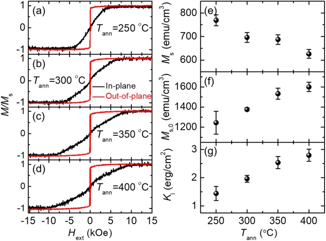
Figure 1 plots the magnetic hysteresis loops and associated magnetic properties extracted from VSM measurements. With the increase of Tann, Ms for the W/CoFeB/MgO films decreases from ~780 to ~630 emu cm−3 (Fig. 1e). The PMA in the W/CoFeB/MgO films is dominated by the interface anisotropy (Ki), which increases from 1.4 to 2.8 erg cm−2 (excluding the dead-layer thickness effect) with Tann up to 400 °C (Fig. 1g). If the film thicknesses are corrected by subtracting the dead layer, Ki will change from 1.3 to 1.6 erg cm−2 as Tann increases from 250 to 400 °C, which agrees better with literature values44. Details about the determination of Ki including the dead-layer effect are provided in Section S1 of the Supplementary Information (SI).
Figure 1.
Room temperature magnetic hysteresis loops of W/CoFeB/MgO PMA thin films post-annealed at (a) 250 °C, (b) 300 °C, (c) 350 °C, and (d) 400 °C. Black and red curves denote external magnetic field (Hext) applied along and perpendicular to the film plane, respectively. (e–g) Plots of the effective saturation magnetization (Ms), the intrinsic saturation magnetization (i.e., excluding the effect of the dead layer, Ms,0), and the interfacial anisotropy (Ki) as functions of Tann.
We attribute the decrease of Ms at high Tann to the growth of a dead layer at the CoFeB interfaces, which becomes prominent at higher Tann. To quantitatively determine the thickness of the dead layer as Tann increases, we prepare four sets of PMA stacks of W(7)/CoFeB(t)/MgO(2)/Ta(3). One set contains five stacks with varying thicknesses for the CoFeB layer (t = 1.2, 1.5, 1.8, 2.2, and 2.5 nm) and is post-annealed at a fixed Tann. Four Tann of 250, 300, 350, and 400 °C are used for four sets of the PMA stacks, respectively. The annealing conditions are the same as those for the W(7)/CoFeB(1.2)/MgO(2)/Ta(3) samples discussed previously. We measure the magnetic hysteresis loops of these samples using VSM and plot their saturation magnetization area product (MS × t) as a function of film thickness (t) in Fig. 2. Linear extrapolation of the MS × t data provides the dead-layer thickness, at which the magnetization reduces to zero as illustrated by the x-axis intercept in Fig. 2. The slope of the linear fit also provides intrinsic saturation magnetization (Ms,0), which corresponds to the saturation magnetization after the removal of the dead-layer effect. The values of Ms0 (Fig. 1f) show an increasing trend with Tann from ~1300 to ~1600 emu cm−3, which agrees well with previous measurement results for W/CoFeB/MgO films44.
Figure 2.
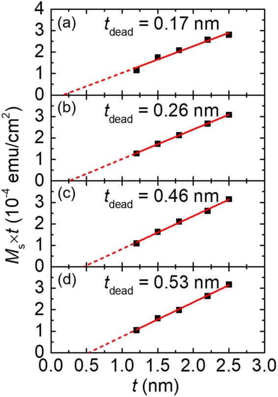
The dead-layer extraction results. (a–d) represent the series of samples annealed at 250, 300, 350, and 400 οC respectively. The tdead value is the extrapolated x-axis intercept from the linear fitting of the thickness-dependent saturation magnetization area product (Ms × t).
Figure 3a depicts the schematic of polar TR-MOKE experiments with the definition of several parameters and angles that are important for the data reduction (Section 2.2). Figure 3b plots the TR-MOKE signals (symbols) and the model fitting of θK (black lines) as functions of time delay for the 400 °C W/CoFeB/MgO sample at an external field angle of θH = 76°. To determine the values of Hk,eff and α, the TR-MOKE measurements are conducted at varying Hext from 2 to 20 kOe. Both the f and τ of the measured oscillations, resulting from the magnetization precession, depend greatly on Hext as predicted by Eqs 1 and 5.
Figure 3.
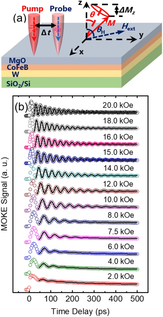
(a) Definition of the parameters and angles used in TR-MOKE experiments. The red circle indicates the magnetization precession. θ is the equilibrium direction of the magnetization. θK is measured by the probe beam at a given time delay (Δt). (b) The TR-MOKE data (open symbols) and model fitting of θK (black curves) for the 400 °C sample at 76°, for varying Hext from 2.0 to 20 kOe.
By repeating this measurement at varying θH, we can show that α is an intrinsic material property, independent of θH. Figure 4a plots the resonance frequencies derived from TR-MOKE and model fittings for the 400 °C sample at two field directions (θH = 76° and 89°). For the data acquired at θH = 89°, a minimum f occurs at Hext ≈ Hk,eff. This corresponds to the smallest amplitude of magnetization precession, when the equilibrium direction of the magnetization is aligned with the applied field direction at the magnitude of Hk,eff40. The dip at this local minimum diminishes when θH decreases, as reflected by the comparison between the red (θH = 89°) and blue (θH = 76°) lines in Fig. 4a. With the Hk,eff extracted from the fitting of frequency data with θH = 89°, we generate the plot of theoretically predicted f vs. Hext (θH = 76° theory, blue line in Fig. 4a), which agrees well with experimental data (open squares in Fig. 4a).
Figure 4.
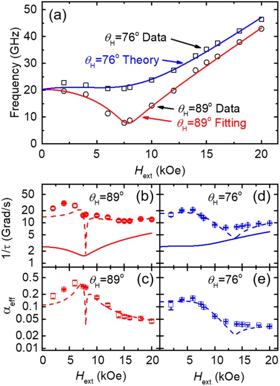
(a) Measured f vs. Hext results for the 400 οC sample at θH = 89° (open circles) and θH = 76° (open squares) and corresponding modeling at θH = 89° (red line) and θH = 76° (blue line). (b) The measured inverse of relaxation time (1/τ) at θH = 89° (open symbols) and the fitting of 1/τ based on Eq. 5 (dotted line). For reference, the first term of 1/τ in Eq. 5 is also plotted (solid line), which accounts for the contribution from the Gilbert damping only. (c) αeff as a function of Hext for θH = 89° (red circles). The dotted line shows the predicted αeff using the α extracted from the fitting of 1/τ. (d,e) depict similar plots of 1/τ and αeff for θH = 76°.
The inverse relaxation time (1/τ) should also have a minimum value near Hk,eff for θH = 89° if the damping was purely from Gilbert damping (as shown by the solid lines in Fig. 4b,d); however, the measured data do not follow this trend. Adding the inhomogeneous term (dotted lines in Fig. 4b,d) more accurately describes the field dependence of the measured 1/τ (open symbols in Fig. 4b,d) It should be noted that the dip of the predicted 1/τ occurs when the frequency derivative term in Eq. 5 approaches zero; however, this is not captured by the measurement. Figure 4c,e depict the field-dependent effective damping (αeff) calculated using the Gilbert damping (α) extracted from fitting the measured 1/τ.
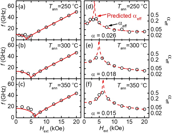
With the knowledge that the value of α extracted with this method is the intrinsic material property, we repeat this data reduction technique for the annealed W/CoFeB/MgO samples discussed in Fig. 1. The symbols in Fig. 5 represent the resonance frequencies and damping constants (both effective damping and Gilbert damping) for all samples measured at θH ≈ 90°. The fittings for the resonance frequency based on Eq. 1 (red lines) are also shown to demonstrate the good agreement between our TR-MOKE measurement and theoretical prediction. The uncertainties of f, τ, and Hk,eff are calculated from the least-squares fitting uncertainty and the uncertainty of measuring Hext with the Hall sensor.
Figure 5.
Results for f (a–c) and αeff (d–f), on a log scale, for individual samples (excluding the 400 °C sample, which is discussed in Fig. 4). The fitting for f is shown as a solid red line. The dashed line in (d–f) indicates the predicted αeff from the values of α extracted from fitting 1/τ. All three samples are measured at θH = 90°.
The summary of the anisotropy and damping measured via TR-MOKE is shown in Fig. 6. Figure 6a plots Hk,eff obtained from VSM (black open circles) and TR-MOKE (blue open squares), both of which exhibit a monotonic increasing trend as Tann becomes higher. Discrepancies in Hk,eff from these two methods can be attributed to the difference in the size of the probing region, which is highly localized in TR-MOKE but sample-averaged in VSM. Since Hk,eff determined from TR-MOKE is obtained from fitting the measured frequency for a localized region, we expect these values more consistently describe the magnetization precession than those obtained from VSM. The increase in Hk,eff with Tann has previously be partially attributed to the crystallization of the CoFeB layer37. For temperatures higher than 350 °C, this increasing trend of Hk,eff begins to lessen, presumably due to the diffusion of W atoms into the CoFeB layer, which is more pronounced at higher Tann. The W diffusion process is also responsible for the decrease in Ms of the CoFeB layer as Tann increases (Fig. 1e). Subsequently, the decrease in Ms leads to a further-reduced demagnetizing energy and thus a larger Hk,eff.
Figure 6.
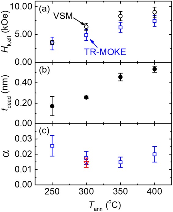
Summary of the magnetic properties of W-seeded CoFeB as a function of Tann. (a) The dependence of Hk,eff on Tann obtained from both the VSM (black open circles) and TR-MOKE fitting (blue open squares). (b) The dependence of dead-layer thickness on Tann. Error bars are from standard error from a linear fit. (c) Damping constants as a function of Tann. The minimum damping constant of α = 0.015 occurs at 350 °C. The values for the all samples are obtained from measurements at θH ≈ 90°. For comparison, α of the reference Ta/CoFeB/MgO PMA sample annealed at 300 °C is also shown as a red triangle in Fig. 6c.
Similar observation of Ms has been reported in literature for Ta/CoFeB/MgO PMA structures and attributed to the growth of a dead layer at the heavy metal/CoFeB interface1. Figure 6b summarizes tdead as a function of Tann with tdead increasing from 0.17 to 0.53 nm as Tann changes from 250 to 400 οC, as discussed in Section II.
Figure 6c depicts the dependence of α on Tann, which first decreases with Tann, reaches a minimum of 0.015 at 350 °C, and then increases as Tann rises to 400 °C. Similar trends have been observed for Ta/CoFeB/MgO previously (minimum α at Tann = 300 °C)37. We speculate that this dependence of damping on Tann is due to two competing effects: (1) the increase in crystallization in the CoFeB layer with Tann which reduces the damping, and (2) the growth of a dead layer, which results from the diffusion of W and B atoms and is prominent at higher Tann.
As the amorphous as-deposited CoFeB film begins to form ordered phases at elevated temperatures, the number of scattering sites in the film tend to decrease45,46. The increase in crystallinity of the W/CoFeB/MgO film with Tann is demonstrated by the XRD analysis detailed in Section S5 of the SI. At Tann = 400 °C, the dead-layer formation leads to a larger damping presumably due to an increase in scattering sites (diffused W atoms) that contribute to spin-flip events, as described by the Elliot-Yafet relaxation mechanisms18. Additionally, W atoms can increase the spin-orbit coupling and thus the damping as the inter-diffusion increases with Tann47. The observation that our W-seeded samples still sustain excellent PMA properties at Tann = 400 °C confirms their enhanced thermal stability, compared with Ta/CoFeB/MgO stacks which fail at Tann = 350 °C or higher.
While the damping constants are comparable for the W/CoFeB/MgO and Ta/CoFeB/MgO films annealed at 300 °C, our work focuses on the enhanced thermal stability of W-seeded CoFeB PMA films that can maintain a relatively low damping constant (0.020 at 400 °C). Such an advantage enables W-seeded CoFeB layers to be viable and promising alternatives to Ta/CoFeB/MgO, which is currently widely used in spintronic devices.
Conclusion
In summary, we deposit a series of W-seeded CoFeB PMA films with varying annealing temperatures up to 400 °C and conduct ultrafast all-optical TR-MOKE measurements to study their magnetization precession dynamics. The Gilbert damping, as an intrinsic material property, is proven to be independent of measurement conditions, such as the amplitudes and directions of the applied field. The damping constant varies with Tann, first decreasing and then increasing, leading to a minimum of α = 0.015 for the sample annealed at 350 °C. Due to the dead-layer growth, the damping constant slightly increases to α = 0.020 at Tann = 400 °C, which demonstrates the improved enhanced thermal stability of W/CoFeB/MgO over the Ta/CoFeB/MgO structures. This strongly suggests the great potential of W/CoFeB/MgO PMA systems for future spintronic device integration that requires materials to sustain a processing temperature as high as 400 °C.
Electronic supplementary material
Acknowledgements
This work is supported by C-SPIN (award #: 2013-MA-2381), one of six centers of STARnet, a Semiconductor Research Corporation program, sponsored by MARCO and DARPA. X.H. thanks Niron Magnetics, Inc. for financial support. The sample structural characterizations (XRD and XRR) were performed at the University of Minnesota Characterization Facility (CharFac), which received capital equipment funding from the University of Minnesota MRSEC under NSF Award DMR-1420013. The authors would like to thank Prof. Paul Crowell and Dr. Changjiang Liu for valuable discussions.
Author Contributions
D.Z. and D.L. conceived the idea and designed the measurements, under the supervision of X.W. and J.W., D.Z. synthesized the CoFeB samples and conducted VSM measurements. X.H. performed all the XRD and XRR characterizations. D.L. carried out the TR-MOKE measurements and led the manuscript writing with a portion of the materials provided by D.Z., J.Z., D.L. and D.Z. contributed to analyzing the data and revising the manuscript. All authors have reviewed and discussed the results and conclusions of this work.
Competing Interests
The authors declare no competing interests.
Footnotes
Publisher's note: Springer Nature remains neutral with regard to jurisdictional claims in published maps and institutional affiliations.
Dustin M. Lattery and Delin Zhang contributed equally.
Contributor Information
Jian-Ping Wang, Email: jpwang@umn.edu.
Xiaojia Wang, Email: wang4940@umn.edu.
Electronic supplementary material
Supplementary information accompanies this paper at 10.1038/s41598-018-31642-9.
References
- 1.Ikeda S, et al. A perpendicular-anisotropy CoFeB-MgO magnetic tunnel junction. Nat. Mater. 2010;9:721–724. doi: 10.1038/nmat2804. [DOI] [PubMed] [Google Scholar]
- 2.Sato H, et al. Properties of magnetic tunnel junctions with a MgO/CoFeB/Ta/CoFeB/MgO recording structure down to junction diameter of 11 nm. Appl. Phys. Lett. 2014;105:062403. doi: 10.1063/1.4892924. [DOI] [Google Scholar]
- 3.Sun JZ, et al. Spin-torque switching efficiency in CoFeB-MgO based tunnel junctions. Phys. Rev. B. 2013;88:104426. doi: 10.1103/PhysRevB.88.104426. [DOI] [Google Scholar]
- 4.Zhu J, et al. Voltage-induced ferromagnetic resonance in magnetic tunnel junctions. Phys. Rev. Lett. 2012;108:197203. doi: 10.1103/PhysRevLett.108.197203. [DOI] [PubMed] [Google Scholar]
- 5.Wang WG, Li MG, Hageman S, Chien CL. Electric-field-assisted switching in magnetic tunnel junctions. Nat. Mater. 2012;11:64–68. doi: 10.1038/nmat3171. [DOI] [PubMed] [Google Scholar]
- 6.Kanai S, et al. Electric field-induced magnetization reversal in a perpendicular-anisotropy CoFeB-MgO magnetic tunnel junction. Appl. Phys. Lett. 2012;101:122403. doi: 10.1063/1.4753816. [DOI] [Google Scholar]
- 7.Yu GQ, et al. Switching of perpendicular magnetization by spin-orbit torques in the absence of external magnetic fields. Nat. Nanotechnol. 2014;9:548–554. doi: 10.1038/nnano.2014.94. [DOI] [PubMed] [Google Scholar]
- 8.Bhowmik D, You L, Salahuddin S. Spin Hall effect clocking of nanomagnetic logic without a magnetic field. Nat. Nanotechnol. 2014;9:59–63. doi: 10.1038/nnano.2013.241. [DOI] [PubMed] [Google Scholar]
- 9.Liu LQ, et al. Spin-torque switching with the giant spin Hall effect of tantalum. Science. 2012;336:555–558. doi: 10.1126/science.1218197. [DOI] [PubMed] [Google Scholar]
- 10.Jiang WJ, et al. Blowing magnetic skyrmion bubbles. Science. 2015;349:283–286. doi: 10.1126/science.aaa1442. [DOI] [PubMed] [Google Scholar]
- 11.Yu G, et al. Room-temperature skyrmion shift device for memory application. Nano Lett. 2017;17:261–268. doi: 10.1021/acs.nanolett.6b04010. [DOI] [PubMed] [Google Scholar]
- 12.Diao ZT, et al. Spin-transfer torque switching in magnetic tunnel junctions and spin-transfer torque random access memory. J. Phys.: Condens. Mat. 2007;19:165209. [Google Scholar]
- 13.Manipatruni S, Nikonov DE, Young IA. Energy-delay performance of giant spin Hall effect switching for dense magnetic memory. Appl. Phys. Express. 2014;7:103001. doi: 10.7567/APEX.7.103001. [DOI] [Google Scholar]
- 14.Annunziata AJ, et al. Materials investigation for thermally-assisted magnetic random access memory robust against 400 °C temperatures. J. Appl. Phys. 2015;117:17B739. doi: 10.1063/1.4917066. [DOI] [Google Scholar]
- 15.Miyakawa N, Worledge DC, Kita K. Impact of Ta diffusion on the perpendicular magnetic anisotropy of Ta/CoFeB/MgO. IEEE Magn. Lett. 2013;4:1000104. doi: 10.1109/LMAG.2013.2240266. [DOI] [Google Scholar]
- 16.Yang S, et al. Thermally stable perpendicular magnetic anisotropy features of Ta/TaOx/Ta/CoFeB/MgO/W stacks via TaOx underlayer insertion. J. Appl. Phys. 2014;116:113902. doi: 10.1063/1.4895709. [DOI] [Google Scholar]
- 17.Gan HD, et al. Origin of the collapse of tunnel magnetoresistance at high annealing temperature in CoFeB/MgO perpendicular magnetic tunnel junctions. Appl. Phys. Lett. 2011;99:252507. doi: 10.1063/1.3671669. [DOI] [Google Scholar]
- 18.Elliott RJ. Theory of the effect of spin-orbit coupling on magnetic resonance in some semiconductors. Phys. Rev. 1954;96:266–279. doi: 10.1103/PhysRev.96.266. [DOI] [Google Scholar]
- 19.Suhl H. Theory of the magnetic damping constant. IEEE Trans. Magn. 1998;34:1834–1838. doi: 10.1109/20.706720. [DOI] [Google Scholar]
- 20.Ikeda S, et al. Tunnel magnetoresistance of 604% at 300 K by suppression of Ta diffusion in CoFeB∕MgO∕CoFeB pseudo-spin-valves annealed at high temperature. Appl. Phys. Lett. 2008;93:082508. doi: 10.1063/1.2976435. [DOI] [Google Scholar]
- 21.Liu T, Zhang Y, Cai JW, Pan HY. Thermally robust Mo/CoFeB/MgO trilayers with strong perpendicular magnetic anisotropy. Sci. Rep. 2014;4:5895. doi: 10.1038/srep05895. [DOI] [PMC free article] [PubMed] [Google Scholar]
- 22.Almasi H, et al. Enhanced tunneling magnetoresistance and perpendicular magnetic anisotropy in Mo/CoFeB/MgO magnetic tunnel junctions. Appl. Phys. Lett. 2015;106:182406. doi: 10.1063/1.4919873. [DOI] [Google Scholar]
- 23.Cho S, Baek S-HC, Lee K-D, Jo Y, Park B-G. Large spin Hall magnetoresistance and its correlation to the spin-orbit torque in W/CoFeB/MgO structures. Sci. Rep. 2015;5:14668. doi: 10.1038/srep14668. [DOI] [PMC free article] [PubMed] [Google Scholar]
- 24.Pai CF, et al. Spin transfer torque devices utilizing the giant spin Hall effect of tungsten. Appl. Phys. Lett. 2012;101:122404. doi: 10.1063/1.4753947. [DOI] [Google Scholar]
- 25.Liu J, Ohkubo T, Mitani S, Hono K, Hayashi M. Correlation between the spin Hall angle and the structural phases of early 5d transition metals. Appl. Phys. Lett. 2015;107:232408. doi: 10.1063/1.4937452. [DOI] [Google Scholar]
- 26.He C, et al. Spin-torque ferromagnetic resonance measurements utilizing spin Hall magnetoresistance in W/Co40Fe40B20/MgO structures. Appl. Phys. Lett. 2016;109:202404. doi: 10.1063/1.4967843. [DOI] [Google Scholar]
- 27.Skowroński W, et al. Underlayer material influence on electric-field controlled perpendicular magnetic anisotropy in CoFeB/MgO magnetic tunnel junctions. Phys. Rev. B. 2015;91:184410. doi: 10.1103/PhysRevB.91.184410. [DOI] [Google Scholar]
- 28.Chatterjee J, et al. Enhanced annealing stability and perpendicular magnetic anisotropy in perpendicular magnetic tunnel junctions using W layer. Appl. Phys. Lett. 2017;110:202401. doi: 10.1063/1.4983159. [DOI] [Google Scholar]
- 29.van Kampen M, et al. All-optical probe of coherent spin waves. Phys. Rev. Lett. 2002;88:227201. doi: 10.1103/PhysRevLett.88.227201. [DOI] [PubMed] [Google Scholar]
- 30.Mizukami S, et al. Laser-induced fast magnetization precession and Gilbert damping for CoCrPt alloy thin films with perpendicular magnetic anisotropy. Appl. Phys. Express. 2010;3:123001. doi: 10.1143/APEX.3.123001. [DOI] [Google Scholar]
- 31.Mizukami S, et al. Long-lived ultrafast spin precession in manganese alloys films with a large perpendicular magnetic anisotropy. Phys. Rev. Lett. 2011;106:117201. doi: 10.1103/PhysRevLett.106.117201. [DOI] [PubMed] [Google Scholar]
- 32.Iihama S, et al. Observation of precessional magnetization dynamics in L10-FePt thin films with different L10 order parameter values. Jpn. J. Appl. Phys. 2013;52:073002. doi: 10.7567/JJAP.52.073002. [DOI] [Google Scholar]
- 33.Zhu J, Wu X, Lattery DM, Zheng W, Wang X. The ultrafast laser pump-probe technique for thermal characterization of materials with micro/nanostructures. Nanosc. Microsc. Therm. 2017;21:177–198. doi: 10.1080/15567265.2017.1313343. [DOI] [Google Scholar]
- 34.Takahashi YK, et al. Increased magnetic damping in ultrathin films of Co2FeAl with perpendicular anisotropy. Appl. Phys. Lett. 2017;110:252409. doi: 10.1063/1.4989379. [DOI] [Google Scholar]
- 35.You CY, Shin SC. Generalized analytic formulae for magneto-optical Kerr effects. J. Appl. Phys. 1998;84:541–546. doi: 10.1063/1.368058. [DOI] [Google Scholar]
- 36.Krivosik P, Mo N, Kalarickal S, Patton CE. Hamiltonian formalism for two magnon scattering microwave relaxation: Theory and applications. J. Appl. Phys. 2007;101:083901. doi: 10.1063/1.2717084. [DOI] [Google Scholar]
- 37.Iihama S, et al. Gilbert damping constants of Ta/CoFeB/MgO(Ta) thin films measured by optical detection of precessional magnetization dynamics. Phys. Rev. B. 2014;89:174416. doi: 10.1103/PhysRevB.89.174416. [DOI] [Google Scholar]
- 38.Kittel C. On the theory of ferromagnetic resonance absorption. Phys. Rev. 1948;73:155–161. doi: 10.1103/PhysRev.73.155. [DOI] [Google Scholar]
- 39.Ma L, et al. Tunable magnetization dynamics in disordered FePdPt ternary alloys: Effects of spin orbit coupling. J. Appl. Phys. 2014;116:113908. doi: 10.1063/1.4895480. [DOI] [Google Scholar]
- 40.Mizukami S. Fast magnetization precession and damping for magnetic films with high perpendicular magnetic anisotropy. J. Magn. Soc. Jpn. 2015;39:1–7. doi: 10.3379/msjmag.1412R001. [DOI] [Google Scholar]
- 41.Suhl H. Ferromagnetic resonance in nickel ferrite between one and two kilomegacycles. Phys. Rev. 1955;97:555–557. doi: 10.1103/PhysRev.97.555.2. [DOI] [Google Scholar]
- 42.Wang DS, et al. High thermal stability and low Gilbert damping constant of CoFeB/MgO bilayer with perpendicular magnetic anisotropy by Al capping and rapid thermal annealing. Appl. Phys. Lett. 2014;104:142402. doi: 10.1063/1.4870770. [DOI] [Google Scholar]
- 43.Capua A, Yang SH, Phung T, Parkin SSP. Determination of intrinsic damping of perpendicularly magnetized ultrathin films from time-resolved precessional magnetization measurements. Phys. Rev. B. 2015;92:9. doi: 10.1103/PhysRevB.92.224402. [DOI] [Google Scholar]
- 44.An G-G, et al. Highly stable perpendicular magnetic anisotropies of CoFeB/MgO frames employing W buffer and capping layers. Acta Mater. 2015;87:259–265. doi: 10.1016/j.actamat.2015.01.022. [DOI] [Google Scholar]
- 45.Yilgin R, Oogane M, Yakata S, Ando Y, Miyazaki T. Intrinsic Gilbert damping constant in Co2MnAl Heusler alloy films. IEEE Trans. Magn. 2005;41:2799–2801. doi: 10.1109/TMAG.2005.854832. [DOI] [Google Scholar]
- 46.Iihama S, et al. Low precessional damping observed for L10-ordered FePd epitaxial thin films with large perpendicular magnetic anisotropy. Appl. Phys. Lett. 2014;105:142403. doi: 10.1063/1.4897547. [DOI] [Google Scholar]
- 47.Skowroński W, et al. Temperature dependence of spin-orbit torques in W/CoFeB bilayers. Appl. Phys. Lett. 2016;109:062407. doi: 10.1063/1.4960793. [DOI] [Google Scholar]
Associated Data
This section collects any data citations, data availability statements, or supplementary materials included in this article.


