Abstract

The development of well-adhering, easily producible photonic reflective coatings is still a challenge. Here, an easy-to-produce, industrial viable process is reported that uses a primer layer of the so-called type II photoinitiator to obtain an excellent adhesion between a plastic substrate and one-dimensional (1D) photonic liquid crystalline coatings. Furthermore, a good alignment of the reactive cholesteric liquid crystal mixture is obtained using a bar-coating process, without alignment layers or surfactants. After photopolymerization, cross-hatch tape tests show a good adhesion of the photonic coating having a reflection band of 50% transmission with almost no scattering. Additionally, we demonstrate the ability to create well-adhering ∼100% reflective coatings by coating double layers and the ability to create single-layered cholesteric broadband reflectors using solely a reactivity gradient created by the primer layer. Our new interfacial method gives new opportunities to use reflecting 1D photonic coatings in industrial processes and applications and allows the bonding of almost any polymer to a plastic substrate.
Keywords: liquid crystals, polycarbonate, alignment, adhesion, photonic reflective coatings
Introduction
For many applications, reflectance of specific wavelengths is highly desired to create additional functionalities to materials.1−5 Using one-dimensional (1D) photonic crystals, a selective wavelength region proportional to the periodic modulation of alternating refractive indices is reflected as iridescent colors, as is shown in nature by, for example, the Morpho butterflies and Scarabaeidae beetles.6 These natural photonic structures have inspired scientists to fabricate artificial photonic materials for applications such as in sensors,2 security labels,7 displays,8,9 and rewritable papers.10,11 The 1D photonic crystals can also be useful for applications in buildings or car windows to cool down the interiors because of the reflectance of heat generated by infrared (IR) solar radiation, while maintaining transparency in the visible range.3,12
A highly suitable method to mimic this photonic reflection observed in nature is by using cholesteric liquid crystals (Ch-LCs). Because of the helical twist in the molecular structure and the resulting periodic refractive index variation, the Ch-LC coatings can act as Bragg reflectors.13 These coatings can be prepared by photopolymerization of a reactive acrylate mesogenic Ch-LC mixture containing a type I photoinitiator such as Irgacure. The alignment of the Ch-LC coatings is of high importance for the ability to properly reflect light of a specific wavelength range. Currently, most Ch-LC films are fabricated sandwiched between glass plates14−16 or as adhesive foils, as produced by 3M and BASF. However, to be able to apply the desired properties to the existing exteriors without delamination issues, coatings are far more favorable in industry. Therefore, an increasing interest is observed with regard to the coated cholesteric reflectors.17−19 For this, glass substrates are covered with thin alignment layers to ensure planar (parallel to the substrate) alignment of the reactive liquid crystals, leaving several noncovalently bound interfaces susceptible for delamination. Also, surfactants are often added to maintain a proper alignment near the air interface. Besides, optical transparent plastics are used increasingly in industry as a replacement for glass. Weight reduction, toughness, flexibility, heat resistance, and high impact strength make, for example, polycarbonate (PC) a desirable material for application in windows and roofings in cars, buildings, and constructions.20 Several methods have been developed that enable the functionalization of PC. These methods, however, often require expensive, specialized equipment21−23 or create toxic side products.24−26 Moreover, most methods are based on chain-scissoring of the PC backbones at the surface.27−30 Therefore, short degraded polymer chains are formed, which form a weak link between the substrate and the coating.28−30 Coatability of aligned reactive mesogenic liquid crystalline phases with excellent adhesion and industrial feasible processes to plastic surfaces appears to be absent in the literature. Currently, the fabrication of such materials requires multiple processing steps is rarely tested. For applications, the number of processing steps needs to be reduced enormously, and adhesion needs to be dramatically increased.
In this report, a transparent primer was deposited on the PC substrate, on which Ch-LC was coated and cured. The primer contains the type II photoinitiator benzophenone (BP) that initiates polymerization via intermolecular hydrogen abstraction, creating a radical in their near surrounding without breaking the C–C bonds of the backbone.31 The covalent bond formed ensures an excellent adhesion at the interface between the substrate and the coating.32 The homogeneity and penetration depths of the photoinitiator during the pretreatment step are investigated in more detail. Next to the increased adhesive properties, an excellent alignment of the LC molecules in the polymer network is obtained with an industrial feasible approach, using no alignment layers. It is also shown that this method can be repeated for the adherence of double-layered coatings to obtain near-100% cholesteric reflective layers and to prepare broadband reflective coatings, minimizing the successive coating layers without adding additional UV absorbers.3,14,33
Experimental Section
Materials
PC was kindly provided by SABIC; DB335 and DB162 were received from Philips Research Laboratory. The photoinitiator BP was purchased from Sigma-Aldrich; the liquid crystals RM23, RM105, RM82, RM257, and RM96 from Merck; the chiral dopant LC756 from BASF; and ethanol from Biosolve.
BP Treatment
A 10 wt % (unless stated otherwise) of BP was dissolved in ethanol. The substrate was heated to 40 °C; an approximately 30 cm2 PC was wetted by 0.25 mL BP solution, and the solvent was allowed to evaporate for 15–20 min.
Coating Procedure
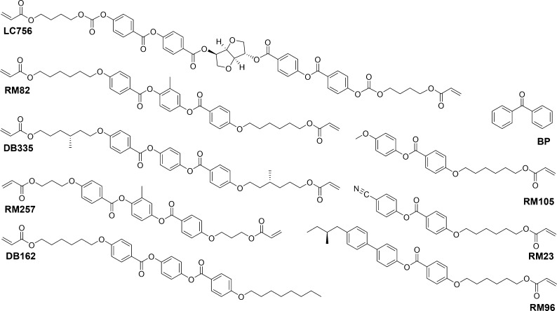
The treated PC substrates were coated with Ch-LC mixtures (Figure 1) at 40 °C using a gap applicator with a 30 μm gap height. The coatings were subsequently photopolymerized through the substrate in a nitrogen atmosphere at room temperature (RT) using UV light (at an intensity of 30 mW/cm2 in the range 320–390 nm). The formulations of the coatings were as follows
Figure 1.
Molecular structures of the chemicals used.
Mixture I: LC756 (3.7 wt %)/RM82 (20 wt %)/RM105 (43 wt %)/RM23 (31.3 wt %)/BP (2 wt %).
Left-handed mixture II: DB162 (40 wt %)/DB335 (28 wt %)/RM105 (31 wt %)/BP (1 wt %).
Right-handed mixture III: RM257 (36 wt %)/RM96 (35 wt %)/RM105 (28 wt %)/BP (1 wt %).
Mixture IV: LC756 (2.5 wt %)/RM82 (20 wt %)/RM105 (45 wt %)/RM23 (32.5 wt %).
Double-Layered Coating Procedure
The left-handed mixture II was coated on a treated PC substrate at 70 °C using a gap applicator with a 30 μm gap height. The coating was subsequently photopolymerized through the substrate in a nitrogen atmosphere at approximately 70 °C using UV light (at an intensity of 30 mW/cm2 in the range 320–390 nm). The coating was treated with BP as described above. Subsequently, the right-handed mixture III was coated on top at RT, using again the gap applicator with 30 μm gap height and cured at RT, similar to the first coating layer.
Cross-hatch Tape Test
By using a razor blade, a cross-hatch pattern was formed on which a Tesa 4651 tape was applied and pressed firmly. The tape was removed quickly using a little extra force. The remaining coating on the substrate was judged according to the ISO 2409 standards, scaling the adhesion from GT0 to GT5, in which GT0 indicates excellent adhesion and GT5 complete delamination.
Characterization
Dispersive Raman analysis was performed on the cryo-cut cross sections of the pretreated PC substrates with a Bruker SENTERRA dispersive Raman microscope, using a 532 nm laser (20 and 10 Mw) and a 100× objective. Attenuated total reflection Fourier transform infrared (ATR–FTIR) mapping was performed on a PerkinElmer Spotlight 400 FTIR-imaging system with a germanium ATR crystal. A 200 × 200 μm2 area was measured by individual points with a 1.5 μm distance and a 3 μm spatial resolution. Optical microscopy (OM) imaging was carried out with an Olympus BX60 or Keyence VHX 5000 microscope. The images were viewed using UV illumination to localize BP. UV–vis spectroscopy was performed on a PerkinElmer LAMBDA 750 spectrometer equipped with a 150 mm integrating sphere. The transmission electron microscopy (TEM) images of the ultratomed (at −120 °C) cross sections of PC substrates coated with Ch-LCs were observed using a FEI Tecnai T12 microscope, with an operating voltage of 100 kV. For atomic force microscopy (AFM) analysis, the PC substrates coated with LCN were cut to size, held between holders, and microtomed at RT, and the cross sections were characterized with a Bruker Dimension FastScan microscope, using a quantitative nanoscale mechanical (QNM) mode, at 1 and 0.5 Hz, RT.
Results and Discussion
Fabrication of the Ch-LC Coating on PC
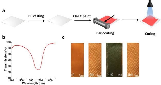
The Ch-LC mixtures initially used (Figure 1) were developed to obtain a reflectance peak in the visible light regime and a processing temperature near RT. A paint was created with the reflection band centered around 660 nm to visualize the alignment capabilities. The PC was pretreated with a BP layer to improve adhesion (see Experimental Section) and coated with the Ch-LC mixture I, using an easy-to-process bar-coating approach without additional alignment layers. The coating was followed by curing by illumination through the substrate with UV light (30 mW/cm2 in the range of 320–390 nm) at 40 °C for 5 min (Figure 2a).
Figure 2.
(a) Method of preparation and coating of Ch-LC paints using an easy-to-process bar-coating technique. (b) Transmission spectrum of the Ch-LC coating after the curing process using mixture I. (c) Cross-hatch tape test procedure: (i) Ch-LC coating of mixture I on pretreated PC. (ii) Cross-hatch pattern prior to the tape test. (iii) Ch-LC coating covered with a Tesa 4651 tape. (iv) Adhered coating after the rapid removal of the tape showing excellent adhesion (GT0).
The transmission spectrum of an orange-colored Ch-LC coating (Figure 2b,c(i)) showed a Ch-LC reflection band until 50% transmission with almost no scattering, which indicates that the preparation method used results in a planar alignment of the liquid crystals.
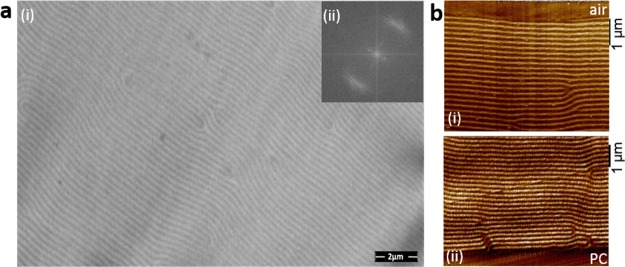
The photonic coatings were further analyzed by TEM. As shown in the TEM image (Figure 3a), visualizing the cholesteric lines, the majority of the cholesteric lines are parallel to each other, meaning that the LCs share a common director. Also, in the two-dimensional (2D) fast Fourier transformed image, a regular spacing of 0.21 μm was observed with a strong directional order, which is in agreement with the reflection band centered at 660 nm, measured with UV–vis spectroscopy (Figure 2b). To investigate the alignment at the substrate and surface interfaces, QNM-AFM measurements were performed on the cross section of the liquid crystalline films near those interfaces, visualizing again the cholesteric lines (Figure 3b). Also here, the aligned Ch-LC phases were observed with only minor defect, for which no alignment layers or surfactants were needed. Using this Ch-LC mixture and the bar-coating technique, shear is solely enough to ensure a proper planar alignment caused by the higher viscosity of paint because of the lack of solvents during application. Most likely, because of the drag forces between the substrate and the viscous LC mixture, the molecules aligned along a common director, resulting in a well-formed cholesteric reflection band (Figure 2b).
Figure 3.
(a) (i) TEM image of the cholesteric liquid crystalline film after photopolymerization in the cholesteric phase. (ii) 2D fast Fourier transformed TEM image. (b) QNM-AFM adhesion image of a cross section of the (i) coating–air interface and (ii) coating–substrate interface of mixture I coated on pretreated PC after photopolymerization in the cholesteric phase.
Adhesion
To analyze the adhesion of the Ch-LC coating on PC, the cross-hatch tape test was performed on the coatings. The reference samples using no primer layer show severe delamination (GT5) when using either Irgacure or BP as the photoinitiator in the LC mixture (Figure S1, Scheme S1). Only when a pretreatment of the substrate with 10 wt % BP in ethanol solution was performed to increase the radical concentration at the PC–coating interface did the adhesion tremendously improve from GT5 to GT0 (Figure 2c).
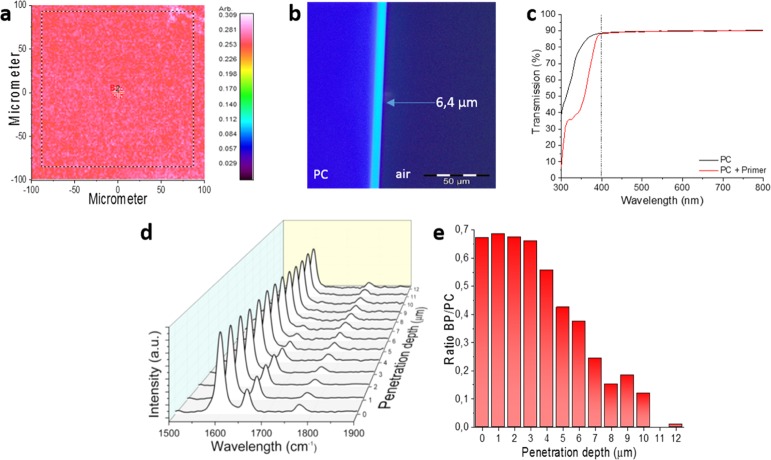
To shed more light on the adhesion of the coating to the PC substrate, several characterization techniques were employed. First, ATR–FTIR mapping of the surface was performed, showing a homogeneous distribution of both BP and PC at the surface, with a relative standard deviation of 4.5% (Figures 4a and S2). To gain more insight into the uniformity and thickness of the BP layer formed, OM using UV illumination was used to characterize the cross section of the PC substrates. Because of the increase in the absorption of UV light of BP with respect to PC, higher concentrations of BP will appear lighter in the OM images (Figures 4b and S3). A uniform layer thickness of 6.4 μm was evidenced. Note that this thickness is calculated based on the visual evaluation of the brightest parts of the OM image, which might differ from the exact layer thickness. As shown in Figure 4c, the optical transparency of the substrate with regard to the visible light region is not influenced by the pretreatment, which is a clue that BP has penetrated into the PC instead of being crystallized at the surface. This penetration is enabled because of the partial swelling of PC in ethanol. To confirm this, cross sections of the treated PC were made and analyzed by Raman spectroscopy. The phenyl ring stretch of the PC at 1600 cm–1 and the C=O bond of BP at 1660 cm–1 were followed along the cross section of the PC with a 1 μm spacing between each measurement. The ratios between the peak areas of the bonds mentioned show that in the BP-rich areas, PC peaks are always present, showing indeed the penetration of BP into the PC substrate (Figures 4d,e and S4). The penetration depth and local concentration of BP are dependent on the initial concentration of BP in the coated solution, which is described in more detail in the Supporting Information.
Figure 4.
(a) Ratio of BP/PC based on the C=O bonds at 1610 cm–1 (BP) and 1780 cm–1 (PC) using ATR–FTIR mapping of the surface of the PC coated with the primer. (b) UV-OM image of the cross sections of PC coated with the primer layer. (c) UV–vis spectra of pure PC and the PC coated with the primer layer. (d) Raman spectra along the cross section of PC with the primer layer. (e) Ratio between the peak areas of BP (1640–1680 cm–1) and PC (1560–1640 cm–1).
Broadband Reflectors and Multiple Layers
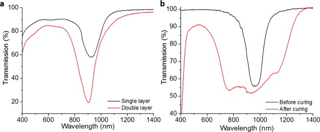
As Ch-LCs reflect only one handedness of the circular polarized light, two coating layers with opposite handedness were coated on top of each other to be able to reach near-100% reflection of a certain wavelength. Because the Ch-LC mixtures possess many CH2 moieties, these networks are susceptible for hydrogen abstraction as well. Therefore, the first coating layer can serve as a substrate for the second Ch-LC layer. Using the same approach as before, the first coating layer was treated with the BP solution and subsequently coated with the Ch-LC mixture with opposite handedness (Figure S5). Mixtures II and III were prepared with the reflection bands centered near 900 nm, which would be suitable for IR reflective coatings (Figure 5a). The mixtures are based on the mixtures previously used to make near-100% reflective Ch-LC films in cells.14 However, a high brittleness was observed in the coatings using these Ch-LC mixtures, causing the LC to partially break during the cross-hatch tape test, resulting in an overall GT3 classification. Nevertheless, the second coating is well-adhered (GT0) to the first coating layer (Figure S6). Optimizing the Ch-LC mixtures will lead to increased mechanical properties.
Figure 5.
Transmission spectra of the (a) Ch-LC coating containing either a single layer using mixture II or a double layer containing both left- and right-handed Ch-LC mixtures II and III and (b) mixture IV coated on pretreated PC before and after photopolymerization in the cholesteric phase.
We also explored if the diffusion of BP can be employed for the formation of broadband reflective coatings. Because of the pretreatment of the substrate with BP, a concentration difference of the photoinitiator is obtained. Using the diffusion of BP into the coating while curing, a difference in the reaction rate of acrylic polymerization is present throughout the thickness of the coating. In a similar way as with the light intensity gradient, this causes the more reactive species to diffuse to the substrate and the less reactive species to deplete to the air–interface, creating a pitch gradient. To enlarge the concentration difference of BP in the coating, the photoinitiator was removed from the coating mixture, leaving only an initial BP concentration at the substrate–coating interface (mixture IV). To obtain a broadband infrared reflection, mixture II was coated on a pretreated PC substrate using a BP-in-ethanol concentration of 0.5 wt %. The coating was illuminated through the substrate with UV light (intensity of 3 mW/cm2 in the range of 320–390 nm) at 40 °C for 20 min, and the sample was post-cured by a high-intensity UV exposure (30 mW/cm2 in the range of 320–390 nm) at 40 °C for 5 min. Using this approach, a well-aligned single-layer broadband coating was formed, without adding any additional UV absorbers (Figure 5b). A 375 nm increase in the bandwidth is reached during polymerization, resulting in a 500 nm broad reflection band. Because of a small decrease in the chiral dopant concentration in mixture IV with respect to mixture I, the area of reflected wavelengths is shifted towards 700−1200 nm. This corresponds to the high-intensity IR region of the solar spectrum, which covers the most energetic wavelengths responsible for the heating of the environment, making this broadband suitable for transparent heat-reflecting coatings.
Conclusions
In conclusion, we presented a potentially relevant industrial process to coat aligned acrylic liquid crystalline monomers to a plastic surface with excellent adhesion. Because of the penetration of BP in the substrate, the acrylic liquid crystalline monomers were grafted from the surface into the network, resulting in a covalently bound coating. Furthermore, no common alignment layers or surfactants were used in this application process to ensure the alignment of the liquid crystals. Nevertheless, a good cholesteric alignment was achieved using shear, resulting in reflective functional coatings. Furthermore, the photoinitiator concentration difference created when removing the photoinitiator from the mixture can be used to create well-defined single-layer cholesteric broadband reflective coatings, which may be suitable for smart window applications. This process could be repeated for multiple layers, as long as the substrate surface has protons available for hydrogen abstraction. Furthermore, the BP ethanol solution can also be printed on the substrate to prepare patterned structural color coatings, and an excellent adhesion of the LC mixture is obtained at the printed area (Movie S1). Our interfacial process provides new opportunities for the application of photonic materials on plastic substrates and is applicable for covalent bonding of other polymers to plastic substrates.
Acknowledgments
The authors thank Julia Verdult-van Aert, Toob Meerman, Lanti Yang, Robin Girod, Ruud van der Heijden, and Mathieu Catusse for their help regarding the analyses.
Glossary
Abbreviations
- PC
polycarbonate
- BP
benzophenone
- Ch-LC
cholesteric liquid crystal
- ATR–FTIR
attenuated total reflection Fourier transform infrared
- OM
optical microscopy
- TEM
transmission electron microscopy
- QNM-AFM
quantitative nanoscale mechanical atomic force microscopy
- RT
room temperature
Supporting Information Available
The Supporting Information is available free of charge on the ACS Publications website at DOI: 10.1021/acsami.8b11583.
Author Contributions
The manuscript was written through contributions of all authors. All authors have given approval to the final version of the manuscript.
This work was financially supported by Saudi Basic Industries Corporation (SABIC).
The authors declare no competing financial interest.
Supplementary Material
References
- Li Q.Intelligent Stimuli Responsive Materials: From Well-Defined Nanostructures to Applications; John Wiley & Sons: Hoboken, NJ, 2013. [Google Scholar]
- Mulder D. J.; Schenning A. P. H. J.; Bastiaansen C. W. M. Chiral-Nematic Liquid Crystals as One Dimensional Photonic Materials in Optical Sensors. J. Mater. Chem. C 2014, 2, 6695–6705. 10.1039/c4tc00785a. [DOI] [Google Scholar]
- Khandelwal H.; Schenning A. P. H. J.; Debije M. G. Infrared Regulating Smart Window Based on Organic Materials. Adv. Energy Mater. 2017, 7, 1602209. 10.1002/aenm.201602209. [DOI] [Google Scholar]
- White T. J.; McConney M. E.; Bunning T. J. Dynamic Color in Stimuli-Responsive Cholesteric Liquid Crystals. J. Mater. Chem. 2010, 20, 9832–9847. 10.1039/c0jm00843e. [DOI] [Google Scholar]
- Lu J.; Gu W.; Wei J.; Zhang W.; Zhang Z.; Yu Y.; Zhou N.; Zhu X. Novel Planar Chiral Dopants with High Helical Twisting Power and Structure-Dependent Functions. J. Mater. Chem. C 2016, 4, 9576–9580. 10.1039/c6tc02557a. [DOI] [Google Scholar]
- Xu J.; Guo Z. Biomimetic Photonic Materials with Tunable Structural Colors. J. Colloid Interface Sci. 2013, 406, 1–17. 10.1016/j.jcis.2013.05.028. [DOI] [PubMed] [Google Scholar]
- Moirangthem M.; Schenning A. P. H. J. Full Color Camouflage in a Printable Photonic Blue-Colored Polymer. ACS Appl. Mater. Interfaces 2018, 10, 4168–4172. 10.1021/acsami.7b17892. [DOI] [PMC free article] [PubMed] [Google Scholar]
- Arsenault A. C.; Puzzo D. P.; Manners I.; Ozin G. A. Photonic-Crystal Full-Colour Displays. Nat. Photonics 2007, 1, 468–472. 10.1038/nphoton.2007.140. [DOI] [Google Scholar]
- Hu W.; Zhao H.; Song L.; Yang Z.; Cao H.; Cheng Z.; Liu Q.; Yang H. Electrically Controllable Selective Reflection of Chiral Nematic Liquid Crystal/Chiral Ionic Liquid Composites. Adv. Mater. 2010, 22, 468–472. 10.1002/adma.200902213. [DOI] [PubMed] [Google Scholar]
- Ge J.; Goebl J.; He L.; Lu Z.; Yin Y. Rewritable Photonic Paper with Hygroscopic Salt Solution as Ink. Adv. Mater. 2009, 21, 4259–4264. 10.1002/adma.200901562. [DOI] [Google Scholar]
- Fang Y.; Ni Y.; Leo S.-Y.; Wang B.; Basile V.; Taylor C.; Jiang P. Direct Writing of Three-Dimensional Macroporous Photonic Crystals on Pressure-Responsive Shape Memory Polymers. ACS Appl. Mater. Interfaces 2015, 7, 23650–23659. 10.1021/acsami.5b07220. [DOI] [PubMed] [Google Scholar]
- Zhang L.; Wang M.; Wang L.; Yang D.-k.; Yu H.; Yang H. Polymeric Infrared Reflective Thin Films with Ultra- Broad Bandwidth. Liq. Cryst. 2016, 43, 750–757. 10.1080/02678292.2016.1142013. [DOI] [Google Scholar]
- Stumpel J. E.; Broer D. J.; Schenning A. P. H. J. Stimuli-Responsive Photonic Polymer Coatings. Chem. Commun. 2014, 50, 15839–15848. 10.1039/c4cc05072j. [DOI] [PubMed] [Google Scholar]
- Khandelwal H.; Loonen R. C. G. M.; Hensen J. L. M.; Schenning A. P. H. J.; Debije M. G. Application of Broadband Infrared Reflector Based on Cholesteric Liquid Crystal Polymer Bilayer Film to Windows and Its Impact on Reducing the Energy Consumption in Buildings. J. Mater. Chem. A 2014, 2, 14622–14627. 10.1039/c4ta03047h. [DOI] [Google Scholar]
- Khandelwal H.; Timmermans G. H.; Debije M. G.; Schenning A. P. H. J. Dual Electrically and Thermally Responsive Broadband Reflectors Based on Polymer Network Stabilized Chiral Nematic Liquid Crystals: The Role of Crosslink Density. Chem. Commun. 2016, 52, 10109–10112. 10.1039/c6cc04721a. [DOI] [PubMed] [Google Scholar]
- Wang L.; Bisoyi H. K.; Zheng Z.; Gutierrez-Cuevas K. G.; Singh G.; Kumar S.; Bunning T. J.; Li Q. Stimuli-Directed Self-Organized Chiral Superstructures for Adaptive Windows Enabled by Mesogen-Functionalized Graphene. Mater. Today 2017, 20, 230–237. 10.1016/j.mattod.2017.04.028. [DOI] [Google Scholar]
- Kragt A. J. J.; Broer D. J.; Schenning A. P. H. J. Easily Processable and Programmable Responsive Semi-Interpenetrating Liquid Crystalline Polymer Network Coatings with Changing Reflectivities and Surface Topographies. Adv. Funct. Mater. 2018, 28, 1704756. 10.1002/adfm.201704756. [DOI] [Google Scholar]
- Zhang W.; Kragt S.; Schenning A. P. H. J.; de Haan L. T.; Zhou G. Easily Processable Temperature-Responsive Infrared-Reflective Polymer Coatings. ACS Omega 2017, 2, 3475–3482. 10.1021/acsomega.7b00454. [DOI] [PMC free article] [PubMed] [Google Scholar]
- Liu D.; Bastiaansen C. W. M.; den Toonder J. M. J.; Broer D. J. Photo-Switchable Surface Topologies in Chiral Nematic Coatings. Angew. Chem., Int. Ed. 2012, 51, 892–896. 10.1002/anie.201105101. [DOI] [PubMed] [Google Scholar]
- Katsamberis D.; Browall K.; Iacovangelo C.; Neumann M.; Morgner H. Highly Durable Coatings for Automotive Polycarbonate Glazing. Prog. Org. Coat. 1998, 34, 130–134. 10.1016/s0300-9440(98)00002-2. [DOI] [Google Scholar]
- Chang S. J.; Kuo S. M.; Lan J. W.; Wang Y. J. Amination of Polycarbonate Surface and Its Application for Cell Attachment. Artif. Cell Blood Substit. Biotechnol. 1999, 27, 229–244. 10.3109/10731199909117696. [DOI] [PubMed] [Google Scholar]
- Bora U.; Sharma P.; Kumar S.; Kannan K.; Nahar P. Photochemical Activation of a Polycarbonate Surface for Covalent Immobilization of a Protein Ligand. Talanta 2006, 70, 624–629. 10.1016/j.talanta.2006.01.021. [DOI] [PubMed] [Google Scholar]
- Baumann L.; Schöller K.; de Courten D.; Marti D.; Frenz M.; Wolf M.; Rossi R. M.; Scherer L. J. Development of Light-Responsive Porous Polycarbonate Membranes for Controlled Caffeine Delivery. RSC Adv. 2013, 3, 23317–23326. 10.1039/c3ra44399j. [DOI] [Google Scholar]
- Klausner M.; Manning M. P.; Baddour R. F.. Surface Modification of Polymeric Materials; Springer, 1990. [Google Scholar]
- Bañuls M.-J.; García-Piñón F.; Puchades R.; Maquieira Á. Chemical Derivatization of Compact Disc Polycarbonate Surfaces for SNPs Detection. Bioconjugate Chem. 2008, 19, 665–672. 10.1021/bc7003457. [DOI] [PubMed] [Google Scholar]
- Tamarit-López J.; Morais S.; Bañuls M.-J.; Puchades R.; Maquieira Á. Development of Hapten-Linked Microimmunoassays on Polycarbonate Discs. Anal. Chem. 2010, 82, 1954–1963. 10.1021/ac902706t. [DOI] [PubMed] [Google Scholar]
- VanDelinder V.; Wheeler D. R.; Small L. J.; Brumbach M. T.; Spoerke E. D.; Henderson I.; Bachand G. D. Simple, Benign, Aqueous-Based Amination of Polycarbonate Surfaces. ACS Appl. Mater. Interfaces 2015, 7, 5643–5649. 10.1021/am508797h. [DOI] [PubMed] [Google Scholar]
- Muir B. W.; Thissen H.; Simon G. P.; Murphy P. J.; Griesser H. J. Factors Affecting the Adhesion of Microwave Plasma Deposited Siloxane Films on Polycarbonate. Thin Solid Films 2006, 500, 34–40. 10.1016/j.tsf.2005.10.060. [DOI] [Google Scholar]
- Lub J.; Vanvroonhoven F.; Vanleyen D.; Benninghoven A. Static Secondary Ion Mass Spectrometry Analysis of Polycarbonate Surfaces. Effect of Structure and of Surface Modification on the Spectra. Polymer 1988, 29, 998–1003. 10.1016/0032-3861(88)90006-7. [DOI] [Google Scholar]
- van der Wel H.; van Vroonhoven F. C. B. M.; Lub J. Surface Modification of Polycarbonate by U.v. Light as Studied by TOF-SIMS. Polymer 1993, 34, 2065–2071. 10.1016/0032-3861(93)90732-p. [DOI] [Google Scholar]
- Allen N. S. Photoinitiators for UV and Visible Curing of Coatings: Mechanisms and Properties. J. Photochem. Photobiol., A 1996, 100, 101–107. 10.1016/s1010-6030(96)04426-7. [DOI] [Google Scholar]
- Deng J.-P.; Yang W.-T.; Rånby B. Surface photografting polymerization of vinyl acetate (VAc), maleic anhydride (MAH), and their charge transfer complex (CTC). III. VAc(3). J. Appl. Polym. Sci. 2001, 80, 1426–1433. 10.1002/app.1232. [DOI] [Google Scholar]
- Broer D. J.; Mol G. N.; van Haaren J. A. M. M.; Lub J. Photo-Induced Diffusion in Polymerizing Chiral-Nematic Media. Adv. Mater. 1999, 11, 573–578. . [DOI] [Google Scholar]
Associated Data
This section collects any data citations, data availability statements, or supplementary materials included in this article.


