Abstract
Motivation
Protein pocket information is invaluable for drug target identification, agonist design, virtual screening and receptor-ligand binding analysis. A recent study indicates that about half holoproteins can simultaneously bind multiple interacting ligands in a large pocket containing structured sub-pockets. Although this hierarchical pocket and sub-pocket structure has a significant impact to multi-ligand synergistic interactions in the protein binding site, there is no method available for this analysis. This work introduces a computational tool based on differential geometry, algebraic topology and physics-based simulation to address this pressing issue.
Results
We propose to detect protein pockets by evolving the convex hull surface inwards until it touches the protein surface everywhere. The governing partial differential equations (PDEs) include the mean curvature flow combined with the eikonal equation commonly used in the fast marching algorithm in the Eulerian representation. The surface evolution induced Morse function and Reeb graph are utilized to characterize the hierarchical pocket and sub-pocket structure in controllable detail. The proposed method is validated on PDBbind refined sets of 4414 protein-ligand complexes. Extensive numerical tests indicate that the proposed method not only provides a unique description of pocket-sub-pocket relations, but also offers efficient estimations of pocket surface area, pocket volume and pocket depth.
Availability and implementation
Source code available at https://github.com/rdzhao/ProteinPocketDetection. Webserver available at http://weilab.math.msu.edu/PPD/.
1 Introduction
The detection of pockets on protein surfaces is a pre-requisite to various tasks in computational molecular biophysics and bioinformatics, such as the determination of the binding site when one attempts to dock a ligand to a protein target and the study of protein functional surfaces. Automatic procedures for potential pocket predictions have been evolving along with the advance in computational capability. Many methods have been designed for protein pocket determination and they can be classified as geometry-based, energy-based, sequence-based, or hybrid (Schmidtke et al., 2011). We review several common categories of these geometry-based methods, namely, probe based methods, grid based methods, Voronoi diagram based methods and marching surface methods that are relevant to our approach.
Based on the idea of rolling a probe to construct solvent excluded surfaces, many probe-based methods have been introduced to detect protein pockets. The pockets are captured by different behaviors with different probe radii. One type of such methods samples protein surfaces using many small probes, and then determines pockets according to surface depressions (Brady and Stouten, 2000; Del Carpio et al., 1993; Ruppert et al., 1997). Another type of such methods uses a large probe radius to create an envelope surface surrounding a protein surface, and then detect the hollow regions between the envelope and the protein surface(Masuya and Doi, 1995; Nayal and Honig, 2006; Yu et al., 2010). There are also methods using combinations of both types of probes (Kawabata and Go, 2007).
The grid based methods, pioneered by Levitt and Banaszak (1992), place a protein inside a regular grid and then scan the grid in a specific order to mark grid points as inside pockets if certain criteria are satisfied (Hendlich et al., 1997; Venkatachalam et al., 2003; Weisel et al., 2007). For instance, grid points can be labeled as not belonging to pockets either by a cube eraser Venkatachalam et al. (2003) or by a probe eraser Weisel et al. (2007). Kufareva et al. (2011) developed a grid potential to assist pocket extraction in grids. It is not only a geometry-based method but also an energy-based one.
Voronoi based methods, introduced by Liang et al. (1998), have been proposed to compare the differences between alpha shapes and the Delaunay triangulation (dual structure to Voronoi diagram) to find pockets, which are represented by the tetrahedra in Delaunay tessellation but not in alpha shapes. A new shape descriptor was later introduced to improve the overall efficiency of this approach (Xie and Bourne, 2007). Voronoi diagram was also used to detect depression regions Kim et al. (2008).
Marching surface methods, proposed by Kleywegt and Jones (1994), detect pockets as isolated cavities formed by offsetting a protein surface along outward normals at a uniform speed. Bock et al. (2007) proposed to trace points on surface along outward normal direction to check whether it has additional intersections with the protein surface, based on which protein surface regions are labeled as pocket or non-pocket.
There are multi-functional tools such as Castp: 3.0 (Dundas et al., 2006) and FPocket (Le Guilloux et al., 2009) that additionally compute physicochemical properties and meta tools such as MetaPocket (Huang, 2009) that combine multiple approaches on top of the geometry. Owing to the advances in protein structural determination, databases about protein pockets and functional surfaces have been established, such as SitesBase database (Gold and Jackson, 2006). Structural databases of protein-ligand complexes (Wang et al., 2004) can also be used to validate pocket detecting tools. Based on large annotated databases and efficient algorithms, web servers, such as PocketQuery (Koes and Camacho, 2012) and MSDmotif (Golovin and Henrick, 2008), have been developed for large scale pocket search.
However, many problems in protein pocket detection remain unsolved. New analysis based on different sequence identity thresholds of a non-redundant set of all holo structures in the PDB indicates that between 47% and 76% of holoproteins can simultaneously bind multiple, interacting ligands in the same pocket that may be comprised of several small but significant sub-pockets (Tonddast-Navaei et al., 2017). The detailed understanding of protein-multi-ligand binding remains of profound importance on many fronts, not least of which includes drug discovery. The hierarchical structure between pockets and sub-pockets is a key to the understanding of the binding of multiple interacting ligands Tonddast-Navaei et al. (2017). Unfortunately, none of the aforementioned methods is designed to describe the hierarchical structure of protein pockets. Additionally, the analysis of protein-ligand binding and drug targets requires computational tools that are able to not only detect protein pockets but also provide more geometric details, including possible sub-pockets and pocket area, volume and depth. Although grid based methods can provide a rough estimate for pocket volume, they typically suffer from efficiency issues. These algorithms usually use the entire grid for the calculation, incurring extra memory consumption and computation time on grid cells far from the protein surface. Further process based on the whole grid will also introduce huge time complexity. Voronoi diagram based methods are efficient in providing area and volume estimates, but lack depth information. Finally, the performance of many current methods depends on many parameters that are not intuitive to tune for given specific pocket requirements. The objective of the present work is to address these difficulties by using geometric partial differential equation (PDE) and algebraic topology.
Inspired by a physical simulation used for surface coloring in 3 D printing, in which air pockets are detected and treated (Zhang et al., 2017), we start from a convex hull surface wrapping around a protein and then press the surface inward until it is tightly in contact with the protein. The space between the convex hull surface and the protein surface is potential locations of pockets, and we use the time that the deforming surface passes through the point as a Morse function to build an evolving topological structure that helps define a pocket hierarchy with desired information.
Lagrangian (mesh) representations are often used in surface deformation as in (Zhang et al., 2017). We opted for an Eulerian (grid) representation, due to the complex surface geometry of the protein, large distortion and potential topological change, which are difficult to handle with a mesh. We encode the surface with an implicit function on a Cartesian grid. This type of methods was originally introduced in simulating two-phase flow by Sussman et al. (1994). The interface can be defined by the zero level set of an implicit function which has a good control flexibility (Osher and Fedkiw, 2006; Peng et al., 1999). We simplify the procedure significantly for efficiency, by combining a simple surface offsetting and mean curvature flow to achieve our goal.
To detect protein pocket hierarchies associate with geometric PDEs, we use persistent homology in the cubical setting. Persistent homology has flourished recently for analyzing geometry and topology of certain space. Early effort dealt with 0-th order topological persistence (Frosini and Landi, 1999), while high dimension topological persistence was formulated by Edelsbrunner et al. (2000). General mathematical theory of persistent homology has been developed by Zomorodian and Carlsson (2005). An efficient software for computing persistent homology on filterations of simplicial complexes and cubical complexes has been developed (Mischaikow and Nanda, 2013). While researchers keep enriching persistent homology theory, its practical applications in biomolecular analysis and landscape analysis have been developed (Xie and Bourne, 2007; Xia et al., 2015). Differential geometry based persistent homology was proposed to proactively predict fullerene isomer curvature stability (Wang and Wei, 2016). Topological landscape tool was built to analyze real world terrain model (Harvey and Wang, 2010). In our approach, as the convex hull surface is deformed, we analyze the persistence of the 0-th dimensional topological invariant induced by the moving surface level set to detect potential pocket (equivalent and dual to membranes around cavities formed between the deforming surface and the protein surface Fig. 1). This approach enables us to analyze pocket area, volume, depth and hierarchical pocket-sub-pocket relation.
Fig. 1.
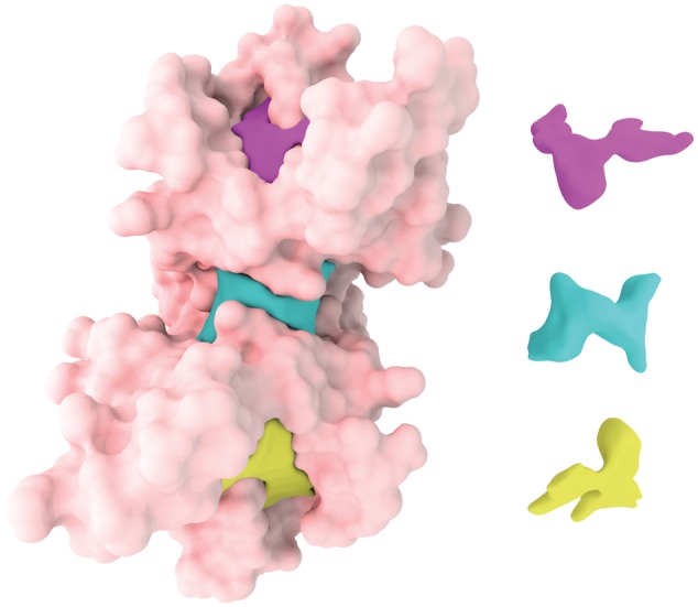
Illustration of detected pockets of protein 1a4r showed by different colors
The rest of the paper is organized as follows. Section 2 discusses the preliminary mathematical background. Section 3 introduces the overall procedures. The implementation of our algorithms is given in Section 4. Section 5 presents the results and applications of the proposed protein pocket detection method. This paper concludes in Section 6.
2 Math background
2.1 Signed distance function
We consider a real-valued function defined on a regular Cartesian grid. An implicit surface is defined by the level set
| (1) |
which is our surface in the Eulerian form. It is possible to take a Lagrangian mesh as the input surface, since the conversion is a standard routine. During surface deformation, we rely on the Eulerian representation to handle the inevitable topological changes. Level set propagation is governed by a general level set equation
| (2) |
where v is the velocity of the flow. As tangential velocity does not change the shape, we can describe surface deformation by the normal component without loss of generality. Thus, one can rewrite the velocity field v as , where is the propagation speed and the sign of v indicates inward or outward motion. The level set equation can be rewritten as
| (3) |
For uniform offset, we can set v to a constant c. A typical surface smoothing deformation is achieved by the mean curvature flow, which offsets each surface point at the speed given by the mean curvature, i.e. . The mean curvature flow level-set equation is given by Osher and Fedkiw (2006)
| (4) |
We can simplify the above two flows if , which can be achieved by choosing to be the signed distance function, i.e. stores the distance from r to the zero level set, with its sign being positive (negative) for outside (inside) locations. As such, the constant-speed normal flow is given by
| (5) |
and the mean curvature flow becomes
| (6) |
The use of the mean curvature flow for biomolecular surface generation was introduced by Bates et al. (2008). Our procedure will drive the surface inward, so the constant c is negative.
Before propagating the zero level set, we first initialize the signed distance function by the eikonal equation to transform the Lagrangian mesh Γ which is the boundary of a 3 D domain Ω into an Eulerian grid embedded signed distance function,
| (7) |
with boundary condition
| (8) |
Fast marching method (FMM), which shares similar ideas from the Dijkstra algorithm, is commonly used to solve the eikonal equation on a regular grid (Sethian, 1996). Alternatively, fast sweeping method can be used (Zhao, 2005). When the regular grid is large, solving this problem in the whole grid is inefficient for both space and time. Typically, a narrow band is used to reduce the memory size. We specify a distance threshold w. Any voxel with a distance above the threshold w will not be used in the calculation. We use the typical choice of w = 3, which guarantees the accurate solution allowed by the resolution of the grid, since the gradient will be correctly calculated for the 0-th level set. Using any larger w will only slow down the calculation without changing the results.
We evolve an initial surface inward without creating sharp corners, so we iteratively update the sign distance function via Equations (5) and (6). The normal flow guarantees that the zero level set moves inward while the mean curvature flow offers a smooth surface representation. The property of is fundamental in simplifying our updating equations. However, the mean curvature flow makes deviate from a signed distance function. As typically done in level set methods, we reinitialize the signed distance function by solving the eikonal equation with the zero level set as the boundary every few iterations.
2.2 Persistent homology
Another technique we employ in our algorithm is persistent homology, a widely applied algebraic topology tool for data analysis, especially in the field of computational biology and chemistry. It significantly reduces geometric complexity by representing essential geometric properties in terms of a sequence of topological invariants parameterized by a geometric function.
2.2.1 Homology group
For a topological space , we define a series of complexes describing different dimensional information of the topological space. Each complex is an Abelian group. The complexes are linked by the boundary maps, which include the homeomorphisms satisfying the condition
| (9) |
The algebraic construction by connecting the complexes by the maps is called a chain complex,
| (10) |
The i-th homology is constructed based on two subsets of complex , the boundary Im, the image of map and the cycle group Ker, the kernel of map . The property in Equation (9) implies that
| (11) |
More precisely, the homology group is defined as the quotient group
| (12) |
When are generated by i-dimensional cells of a tessellation of , homology provides topological information of . Intuitively, contains independent i-dimensional (i-D) holes in .
For instance, the quotient group of a torus describes holes on it. It is constructed from Im, the group of 1 D curves that are boundaries of certain 2 D sub-spaces of , and Ker , the group of all closed 1 D curves. There are two independent types of closed 1 D curves that are not a boundary curve of , which are the generators of the homology. This, in fact, shows the 1 D topological features, a loop around the tunnel and another around the handle of the torus.
2.2.2 Persistent homology
In order to provide relevant geometric information, a geometric parameter can be introduced to provide a dynamic homology analysis for a topology space through filtration, which is a series of sub-space of ,
| (13) |
For our evolving surface, the index is related to the time parameter. A homology class is referred to be born at time i if it is not an image from the inclusion map from to , and to die at time j if it is no longer in the image of the inclusion map from to . The time interval j – i is called the persistence. See, e.g. (Edelsbrunner et al., 2000; Wang and Wei, 2016) for additional details. A major topological feature will have a long persistence. Thus, geometric PDEs can induce persistence to provide a robust description of protein pocket topological features.
3 Algorithm
The relatively simple pockets and their areas, volumes, depths and pocket-sub-pocket relations, can be characterized by the persistence of only homology group , which in fact describes the connected components for the topological space. Describing ring-like pockets can be performed by homology group , but detecting protein cavities requires a different set of the geometric PDEs and would be beyond the scope of the present work.
As we use regular Cartesian grid, cubical complexes and persistent homology at the cubical setting are employed. The associated filtration can be created by a Morse function stored on the 3 D grid, with sub-spaces
| (14) |
where h is the time step size.
For a deforming surface, we can define the Morse function through , i.e. the time when the surface first sweeps through the location r.
One option to evolve the surface is to start from the protein surface and move outward, but the PDEs involved are less stable than those for moving the convex hull inward. Moreover, the time for the inward motion with unit speed also provides a better depth estimate. We prevent the evolving surface from entering the protein surface since we are looking for pockets outside the protein. In this case, the total space is the space between the protein and its convex hull. As the surface moves inward, is shrinking, and it will be separated by protein surface, forming connected components (pieces of the hollow space between the protein surface and the deforming surface at time ti).
We define these pieces with long persistence as potential protein pockets. This procedure can be equivalently, and more efficiently described by a Reeb graph, describing the splitting and merging of the connected components of level sets of . More precisely, the Reeb graph contains nodes, each of which represents a connected component of for certain time ti, and edges connecting nodes at ti and if they are connected through . For our purpose, we only need to construct the Reeb graph to infer potential protein pockets and sub-pockets Fig. 2.
Fig. 2.
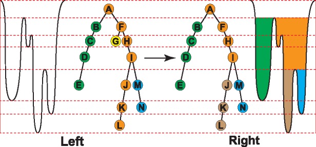
Left: Illustration of Reeb graph. The dashed line represents critical times for the filtration when there will be components newly born or killed. We have extracted four components labeled by different colors. Right: Illustration of a trimmed Reeb graph. The component (i.e. the yellow leaf) that lives for a short period is eliminated. Note that orange path is divided into two components (orange and brown), due to pocket hierarchical relation. Persistent objects are then marked by green, orange, brown and blue regions extracted from nodes B, F, J and M, respectively. Brown and blue are sub-pockets of orange
For our Morse function , the Reeb graph is simply a tree. Starting from a single root, the tree will bifurcate whenever there is a splitting of the connected components. Finally, all connected components will disappear when the surface has deformed to the protein surface.
With persistent homology, we can actually capture all potential pockets regardless of their sizes and the tree provides us with a hierarchy among the pocket candidates. Then, we can use arbitrary geometric or physical pocket dimensions to eliminate those with short persistence as ‘noise’. We elaborate on capturing pockets with high probability by further examining the geometry in the next section.
Algorithm 1 Pocket Detection Algorithm
1: function PocketDetection(model, atoms)
2: BuildConvexHull()
3: BuildSignedDistanceFunction()
4: Initialize()
5: while NotAllSurfaceBlocked() do ▹ Figure 4
6: ReinitializeSDFIfNeeded() ▹ Section 2.1
7: EvolveSurface()
8: ExtractConnectedComponents()
9: BuildReebGraph()
10: ExtractMajorPersistencePath()
11: ExtractPotentialPockets()
4 Implementation
Proper implementation is mandatory for efficiency of Eulerian methods. To reduce memory space usage, we perform a two-pass algorithm to avoid storing the Morse function explicitly in the 3 D grid. In the first pass, we record only the necessary information to build the Reeb graph and extract the major component paths. We then collect the geometric information for the long persistent pockets by evolving the surface with a second pass Fig. 3.
Fig. 3.
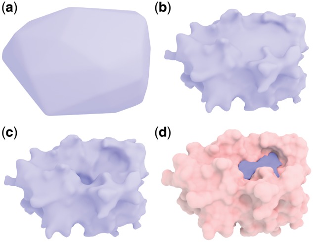
Illustration of the convex hull surface evolution on protein 3kgp. The surface moves inward from the convex hull and finally reaches the protein surface in (a), (b) and (c). (d) Shows the detected pockets
4.1 Input and output
Our algorithm is independent of the type of input surface, e.g. solvent excluded surface (SES). A triangulated SES can be computed by software provided by (Liu et al., 2017). We also use a standard molecule description file, containing the locations and radii of all the atoms for future atom query.
The output provides information on protein pocket candidates, including the depth, area, volume and adjacent atoms for downstream applications. The first three geometry properties are obtained by analyzing the space bounded by the deforming surface and the protein surface. We build a kd-tree for fast access of nearest atom.
4.2 Initialization
Open source software packages exist for convex hull surface generation and solving the eikonal equation. We resort to the Computational Geometry Algorithms Library (CGAL; Fabri and Pion, 2009) for building the convex hull surface from a triangulated SES (Liu et al., 2017) and OpenVDB (Museth, 2013) for the data structures and sub-routines of surface deformation. A surface mesh can be converted into a signed distance function by using an OpenVDB procedure. OpenVDB uses a hierarchical tree structure to achieve narrow band storage, which contributes to the overall efficiency of our implementation.
4.3 Evolving surface
With the narrow band representation of the signed distance function (SDF), moving the surface only amounts to update in each active voxel. We mark each active deforming surface voxel as either blocked or free depending on whether the deforming surface is touching the protein surface at that voxel, which can be determined by comparing the signed distance functions for the deforming surface and for the protein surface. We update for the moving surface only in free voxels and change the signed distance function monotonically in time to prevent moving the surface backwards. The monotonicity prevents the mean curvature flow from overpowering the normal flow motion, while preventing sharp corners from developing near contact regions of the two surfaces. As mentioned before, reinitialization for every few update steps is necessary, since otherwise the level set function will deviate from an SDF.
4.4 Connected component
As mentioned above, the connected components of in the filtration is memory-intensive to compute. Thus, we opt for the equivalent calculation based on surface voxels, which are the active voxels containing a piece of the current zero level set. We then compute the connected components of surface voxels that are not blocked by the protein surface yet.
The idea is illustrated in Figure 4 in 2D, a snapshot of active voxels during the surface deformation. The black curve represents the protein surface, and the red curve represents the deforming surface. Note that for stable implementation, we start the deforming surface from a surface slightly offset outward from the convex hull. Both the deforming surface and the protein surface are stored as zero-level sets of the corresponding signed distance functions. All colored voxels are active. Orange and yellow voxels are surface voxels of the deforming surface, and brown voxels are surface voxels of the protein surface. Orange voxels are blocked by the protein surface, but yellow voxels are still free to move. We further allow the deforming surface to move within the protein surface by a short distance, again for robustness. The voxels between brown voxels and yellow voxels belong to a potential pocket. The free moving piece of the deforming surface will continue evolving inward until it becomes blocked the protein surface.
Fig. 4.
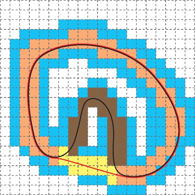
Illustration of basic algorithmic concepts. All colored voxels are active, and the rest inactive. Orange voxels are blocked surface voxels, while yellow voxels are free surface voxels of the deforming surface (indicated by red curve). The black curve indicates the protein surface. The brown voxels represent the currently untouched region of protein surface, which is a pocket in this case
4.5 Reeb graph
We construct the Reeb graph, based on connected components. The persistence of branches in the Reeb graph indicates how likely it corresponds to a real protein pocket. As explained in Section 3, nodes of the Reeb graph corresponds to connected components and edges show their connection through temporal evolution of the surface. As we use a nearly uniform unit speed to evolve the surface along the normal directions, except for small deviations introduced by the mean curvature flow, the persistence well captures the depth information.
Each node is labeled with a persistence computed as the graph distance from the deepest leaf node among its descents. Branches with a small persistence can be trimmed. This does not prevent deep but narrow candidate pockets from being detected. However, the estimated free moving surface area associated with the component can be used as an additional criterion to eliminate those candidates. So both the depth and width thresholds can be easily specified and applied. Finally, we just need to run the second pass to extract the desirable pocket information.
4.6 Geometric feature
Our surface deformation procedure can easily produce geometric features for detected pockets, as each pocket is represented by space bounded by protein surface patches and deforming surface patches, rendering the pocket volume and pocket surface area. We can also extract the opening area by the area of the deforming surface patch, which indicates the pocket width. Pocket depth is naturally defined by the persistence of a certain pocket. More precisely, the depth of a pocket is defined by the persistence measuring the difference between birth and death times multiplied by the surface evolution speed, which is 0.5 times the grid spacing in our implementation.
Such volume and area calculation for level sets is well established. Here, we offer a highly efficient estimation. We simply count the number of voxels that are bounded by the two surfaces as an estimate for volume. The pocket area and horizontal span are estimated by the corresponding surface voxel counts on protein surface patches and deforming surface patches, respectively. We only provide a rough estimate of the surface area, but more accurate results can be calculated as efficiently by weighting different types of surface voxels as in (Mullikin and Verbeek, 1993). Since the voxel count times the volume of voxel provides the volume of a thin shell of about two grid spacing, we estimate the area by dividing this volume by this approximate thickness of the thin shell.
All our thresholds, the minimum required depth, the minimum required horizontal span, and the minimum required volume, are all intuitive parameters, that can be either user-specified or application-determined. The final detected pockets will thus not be too shallow, too narrow or too small.
5 Results and discussion
We validate our method with pocket detection performed on the PDBbind database (Wang et al., 2004) which contains high quality crystal structures of diverse protein-ligand complexes. A residue or a ligand can be represented as sets of atoms, or . A protein can then be represented as a set of residues . All protein atoms are considered. Then we define a set of confirmed pocket residues within a distance d from the surface as
| (15) |
Let be the set of residues in P that are identified as pockets by the program. We say the pocket detection succeeds for a protein if
| (16) |
where r is a ratio (required recall rate). The success rate is the percentage of proteins that our method succeeded to detect the pockets.
One set of proteins and its two subsets are used for validation. The first one containing 4 414 entries is the union of all proteins from the PDBbind refined sets v2007, v2013, v2015, and v2016, and is denoted . The second set containing 2 430 entries is the subset of containing all single chain proteins denoted . The third set containing 290 entries is the PDBbind 2016 core set denoted . The atomic radii are first generated by PDB2PQR software (version 2.1.0; Dolinsky et al., 2007) with CHARMM force field. The pockets are computed for the chain closest to the ligand if a protein contains multiple chains. The performance of the proposed method on the three sets is shown in Table 1.
Table 1.
Performance measured by on the three sets with different distance thresholds (d) and ratio cutoffs (r)
|
(4414) |
(2430) |
(290) |
|||||||
|---|---|---|---|---|---|---|---|---|---|
| d | 0.25 | 0.5 | 0.75 | 0.25 | 0.5 | 0.75 | 0.25 | 0.5 | 0.75 |
| 3Å | 0.91 | 0.86 | 0.78 | 0.94 | 0.89 | 0.83 | 0.95 | 0.89 | 0.81 |
| 4Å | 0.91 | 0.86 | 0.76 | 0.94 | 0.89 | 0.80 | 0.95 | 0.89 | 0.77 |
| 5Å | 0.91 | 0.86 | 0.68 | 0.94 | 0.89 | 0.71 | 0.94 | 0.90 | 0.71 |
Our method successfully captures the majority of the real binding pockets in Table 1. We found that there are three cases where our method cannot detect the provided ligand binding references. (i) The ligand is bound at a rather shallow place. (ii) The ligand is bound at pockets which are formed by more than a single chain. (iii) The ligand is bound at closed cavities, which is beyond the cases that our current method handles. Note that the success rate may appear to drop with increasing d in some cases because the denominator may increase.
In addition to the known pockets, we are able to provide many other pocket candidates with detailed geometric information. For example, in Figure 5, in addition to the binding site of protein 3ao4 confirmed by PDBbind database marked purple, our method also provides other potential candidates.
Fig. 5.
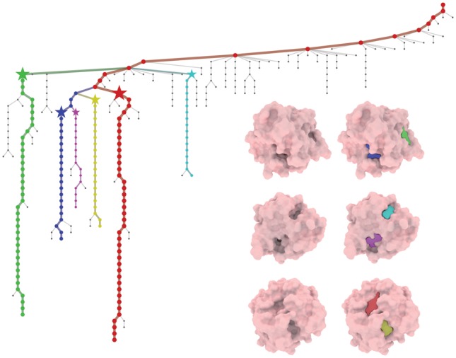
Visualization of detected pockets of protein 3ao4 with the corresponding Reeb graph
Figure 5 shows a specific example of the detected pockets for protein 3ao4. The colored branches in the Reeb graph are among the major persistent candidates, whereas gray paths are eliminated as noise. The color of the major component path is consistent with that for pockets. The pockets are extracted at the stage marked by a star. It can be noticed that pockets detected are highly reliable and resistant to noise. Figure 6 shows that our hierarchical detection procedure finds two sub-pockets (cyan and purple) from a large ancestor pocket (yellow), from which multi-ligand binding with ligand interactions may be suggested (red and green).
Fig. 6.
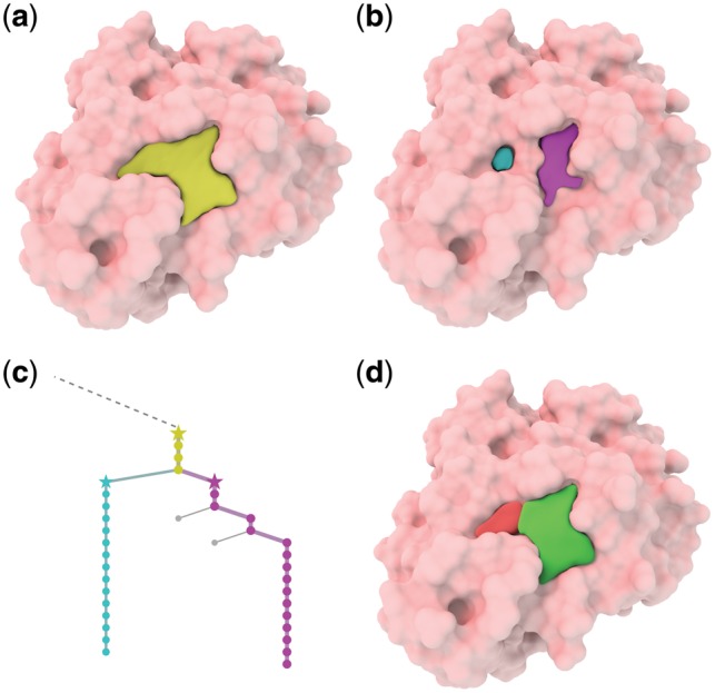
Visualization of ligand interaction suggestions for multi-ligand binding on protein 1tok. (a) A large detected pocket (yellow). (b) Two sub-pockets (cyan and purple) that bifurcate from this large pocket. (c) The corresponding branches in the Reeb graph. Yellow branch bifurcates into two sub-branches (cyan and purple). (d) Our suggestion for multi-ligand (red and green) binding with ligand interactions
Table 2 provides details of geometric properties for all pockets in figures. We also provide statistics for all the test cases. Figure 7a shows memory consumption distribution, which is roughly proportional to , where n is the number of atoms. Figure 7b shows execution time distribution, which is within a reasonable amount of time, no more than 120 s.
Table 2.
Geometric properties of all detected pockets in figures
| Volume(Å3) | Area(Å2) | Depth(Å) | |
|---|---|---|---|
| 1a4r top | 964 | 475 | 4 |
| 1a4r mid | 1227 | 558 | 5 |
| 1a4r bottom | 935 | 463 | 4 |
| 3kgp | 973 | 436 | 8 |
| 3ao4 blue | 569 | 326 | 9 |
| 3ao4 green | 521 | 293 | 5 |
| 3ao4 cyan | 508 | 266 | 7 |
| 3ao4 purple | 672 | 373 | 9 |
| 3ao4 red | 828 | 409 | 7 |
| 3ao4 yellow | 447 | 243 | 5 |
| 1tok yellow | 1252 | 600 | 9 |
| 1tok cyan | 533 | 272 | 7 |
| 1tok purple | 173 | 90 | 6 |
Fig. 7.
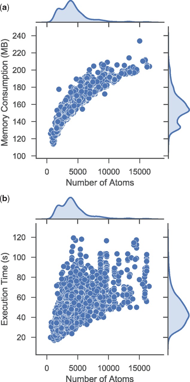
Statistics for all 4 414 test cases
6 Concluding remarks
This work introduces the geometric partial differential equation (PDE) based convex hull surface evolution and associated topological persistence for accurate, efficient and robust detection of protein pockets. The level set function is governed by the unit speed normal flow to measure the pocket surface area, volume and depth. The mean curvature flow is incorporated to ensure a smooth surface representation of protein pockets. These equations are iteratively integrated in the Eulerian representation to allow potential topological changes. The transformation from Lagrangian mesh to the Cartesian grid is accomplished via the eikonal equation. The convex hull surface evolution naturally induces a Morse function and topological persistence. The resulting Reeb graph is utilized to describe the hierarchical relation between protein pockets and sub-pockets, a crucial information for protein-multi-ligand interactions that is not available ever before. Topological persistence also enables the classification and visualization of significant and insignificant pockets and sub-pockets.
Three intuitive parameters describing geometric features are designed for user interaction and control. Efficient algorithms are carefully implemented to avoid potentially excessive memory consumption or execution time pitfalls. On a regular CPU (Intel Xeon 3.77 GHz), the user can obtain results in about a minute without the need to worry about computational resource limitation. Our method has a high locality, which means that the efficiency can be further improved significantly by parallel computing techniques either with GPU such as CUDA, or CPU such as TBB. The resulting implementation of our method exhibits high accuracy in pocket detection in our tests. One limitation of our method is that we do not incrementally handle deforming flexible proteins, but we can treat them frame by frame and establish the correspondence by mapping the pockets to atoms.
Funding
This work was partially supported by NSF grants DMS-1721024, CCF- 1655422 and DMS-1761320 and NIH grant 1R01GM126189-01A1.
Conflict of Interest: none declared.
References
- Bates P., et al. (2008) Minimal molecular surfaces and their applications. J. Comput. Chem., 29, 380–391. [DOI] [PubMed] [Google Scholar]
- Bock M., et al. (2007) Effective Labeling of Molecular Surface Points for Cavity Detection and Location of Putative Binding Sites, World Scientific, Vol. 6, pp. 263–274. [PubMed] [Google Scholar]
- Brady G.P., Stouten P.F. (2000) Fast prediction and visualization of protein binding pockets with pass. J. Computer-Aided Mol. Des., 14, 383–401. [DOI] [PubMed] [Google Scholar]
- Del Carpio C.A., et al. (1993) A new approach to the automatic identification of candidates for ligand receptor sites in proteins:(i) search for pocket regions. J. Mol. Graph., 11, 23–29. [DOI] [PubMed] [Google Scholar]
- Dolinsky T.J., et al. (2007) Pdb2pqr: expanding and upgrading automated preparation of biomolecular structures for molecular simulations. Nucleic Acids Res., 35, W522–W525. [DOI] [PMC free article] [PubMed] [Google Scholar]
- Dundas J., et al. (2006) Castp: computed atlas of surface topography of proteins with structural and topographical mapping of functionally annotated residues. Nucleic Acids Res., 34, W116–W118. [DOI] [PMC free article] [PubMed] [Google Scholar]
- Edelsbrunner H., et al. (2000) Topological persistence and simplification. In: IEEE Proceedings of 41st Annual Symposium on Foundations of Computer Science, 2000, IEEE, pp. 454–463. [Google Scholar]
- Fabri A., Pion S. (2009) Cgal: the computational geometry algorithms library. In: Proceedings of the 17th ACM SIGSPATIAL International Conference on Advances in Geographic Information Systems ,ACM, pp. 538–539. [Google Scholar]
- Frosini P., Landi C. (1999) Size Theory as a Topological Tool for Computer Vision, Vol. 9, Springer, pp. 596–603. [Google Scholar]
- Gold N.D., Jackson R.M. (2006) Sitesbase: a database for structure-based protein–ligand binding site comparisons. Nucleic Acids Res., 34, D231–D234. [DOI] [PMC free article] [PubMed] [Google Scholar]
- Golovin A., Henrick K. (2008) Msdmotif: exploring protein sites and motifs. BMC Bioinformatics, 9, 312. [DOI] [PMC free article] [PubMed] [Google Scholar]
- Harvey W., Wang Y. (2010) Topological landscape ensembles for visualization of scalar-valued functions. Computer Graphics Forum, 29, 993–1002. [Google Scholar]
- Hendlich M., et al. (1997) Ligsite: automatic and efficient detection of potential small molecule-binding sites in proteins. J. Mol. Graph. Model., 15, 359–363. [DOI] [PubMed] [Google Scholar]
- Huang B. (2009) Metapocket: a meta approach to improve protein ligand binding site prediction. OMICS J. Integrative Biol., 13, 325–330. [DOI] [PubMed] [Google Scholar]
- Kawabata T., Go N. (2007) Detection of pockets on protein surfaces using small and large probe spheres to find putative ligand binding sites. Prot. Struct. Funct. Bioinform., 68, 516–529. [DOI] [PubMed] [Google Scholar]
- Kim D., et al. (2008) Pocket extraction on proteins via the voronoi diagram of spheres. J. Mol. Graph. Model., 26, 1104–1112. [DOI] [PubMed] [Google Scholar]
- Kleywegt G.J., Jones T.A. (1994) Detection, delineation, measurement and display of cavities in macromolecular structures. Acta Crystallographica Section D: Biol. Crystallography, 50, 178–185. [DOI] [PubMed] [Google Scholar]
- Koes D.R., Camacho C.J. (2012) Pocketquery: protein–protein interaction inhibitor starting points from protein–protein interaction structure. Nucleic Acids Res., 40, W387–W392. [DOI] [PMC free article] [PubMed] [Google Scholar]
- Kufareva I., et al. (2011) Pocketome: an encyclopedia of small-molecule binding sites in 4d. Nucleic Acids Res., 40, D535–D540. [DOI] [PMC free article] [PubMed] [Google Scholar]
- Le Guilloux V., et al. (2009) Fpocket: an open source platform for ligand pocket detection. BMC Bioinformatics, 10, 168. [DOI] [PMC free article] [PubMed] [Google Scholar]
- Levitt D.G., Banaszak L.J. (1992) Pocket: a computer graphies method for identifying and displaying protein cavities and their surrounding amino acids. J. Mol. Graphics, 10, 229–234. [DOI] [PubMed] [Google Scholar]
- Liang J., et al. (1998) Anatomy of protein pockets and cavities: measurement of binding site geometry and implications for ligand design. Prot. Sci., 7, 1884–1897. [DOI] [PMC free article] [PubMed] [Google Scholar]
- Liu B., et al. (2017) Eses: software for eulerian solvent excluded surface. J. Comput. Chem., 38, 446–466. [DOI] [PubMed] [Google Scholar]
- Masuya M., Doi J. (1995) Detection and geometric modeling of molecular surfaces and cavities using digital mathematical morphological operations. J. Mol. Graphics, 13, 331–336. [DOI] [PubMed] [Google Scholar]
- Mischaikow K., Nanda V. (2013) Morse theory for filtrations and efficient computation of persistent homology. Discrete Comput. Geometry, 50, 330–353. [Google Scholar]
- Mullikin J.C., Verbeek P.W. (1993) Surface area estimation of digitized planes. Bioimaging, 1, 6–16. [Google Scholar]
- Museth K. (2013) Vdb: high-resolution sparse volumes with dynamic topology. ACM Trans. Graph, 32, 1–22. [Google Scholar]
- Nayal M., Honig B. (2006) On the nature of cavities on protein surfaces: application to the identification of drug-binding sites. Prot. Struct. Funct. Bioinform., 63, 892–906. [DOI] [PubMed] [Google Scholar]
- Osher S., Fedkiw R. (2006) Implicit functions. In: Level Set Methods and Dynamic Implicit Surfaces, Springer, pp. 3–16. [Google Scholar]
- Peng D., et al. (1999) A pde-based fast local level set method. J. Comput. Phys., 155, 410–438. [Google Scholar]
- Ruppert J., et al. (1997) Automatic identification and representation of protein binding sites for molecular docking. Prot. Sci., 6, 524–533. [DOI] [PMC free article] [PubMed] [Google Scholar]
- Schmidtke P., et al. (2011) Mdpocket: open-source cavity detection and characterization on molecular dynamics trajectories. Bioinformatics, 27, 3276–3285. [DOI] [PubMed] [Google Scholar]
- Sethian J.A. (1996) A fast marching level set method for monotonically advancing fronts. Proc. Natl. Acad. Sci., 93, 1591–1595. [DOI] [PMC free article] [PubMed] [Google Scholar]
- Sussman M., et al. (1994) A level set approach for computing solutions to incompressible two-phase flow. J. Comput. Phys., 114, 146–159. [Google Scholar]
- Tonddast-Navaei S., et al. (2017) On the importance of composite protein multiple ligand interactions in protein pockets. J. Comput. Chem., 38, 1252–1259. [DOI] [PMC free article] [PubMed] [Google Scholar]
- Venkatachalam C.M., et al. (2003) Ligandfit: a novel method for the shape-directed rapid docking of ligands to protein active sites. J. Mol. Graphics Model., 21, 289–307. [DOI] [PubMed] [Google Scholar]
- Wang B., Wei G.-W. (2016) Object-oriented persistent homology. J. Comput. Phys., 305, 276–299. [DOI] [PMC free article] [PubMed] [Google Scholar]
- Wang R., et al. (2004) The pdbbind database: collection of binding affinities for protein- ligand complexes with known three-dimensional structures. J. Med. Chem., 47, 2977–2980. [DOI] [PubMed] [Google Scholar]
- Weisel M., et al. (2007) Pocketpicker: analysis of ligand binding-sites with shape descriptors. Chem. Central J., 1, 7. [DOI] [PMC free article] [PubMed] [Google Scholar]
- Xia K., et al. (2015) Persistent homology for the quantitative prediction of fullerene stability. J. Comput. Chem., 36, 408–422. [DOI] [PMC free article] [PubMed] [Google Scholar]
- Xie L., Bourne P.E. (2007) A robust and efficient algorithm for the shape description of protein structures and its application in predicting ligand binding sites. BMC Bioinformatics, 8, S9. [DOI] [PMC free article] [PubMed] [Google Scholar]
- Yu J., et al. (2010) Roll: a new algorithm for the detection of protein pockets and cavities with a rolling probe sphere. Bioinformatics, 26, 46–52. [DOI] [PubMed] [Google Scholar]
- Zhang Y., et al. (2017) Coloring 3d printed surfaces by thermoforming. IEEE Trans. Vis. Computer Graphics, 23, 1924–1935. [DOI] [PubMed] [Google Scholar]
- Zhao H. (2005) A fast sweeping method for eikonal equations. Math. Comput., 74, 603–627. [Google Scholar]
- Zomorodian A., Carlsson G. (2005) Computing persistent homology. Discrete Comput. Geometry, 33, 249–274. [Google Scholar]


