

Overview
Introduction
Radial head arthroplasty with a smooth-stemmed metallic modular implant is a reliable treatment option for patients with acute unreconstructible radial head fractures, and good clinical outcomes may be expected beyond 5 years of follow-up (Video 1).
Indications & Contraindications
Step 1: Preoperative Planning
Obtain a careful history and perform a physical examination along with appropriate imaging to facilitate appropriate treatment decisions.
Step 2: Operating Room Setup and Patient Positioning
Perform proper operating room setup and patient positioning, as they are required to gain access to all affected structures around the elbow in a safe and efficient manner.
Step 3: Approach
Make a midline posterior skin incision with development of a full-thickness lateral fasciocutaneous flap or use a direct lateral incision; the deep interval is determined on the basis of the integrity of the LCL.
Step 4: Radial Head Excision
Remove and preserve all fragments of the radial head for implant sizing.
Step 5: Implant Sizing
Implant a prosthesis that closely replicates the dimensions of the native radial head, which is the primary goal of the procedure.
Step 6: Stem Broaching
Sequentially broach the canal until good cortical contact is achieved and undersize the definitive stem by 1 mm to allow implant movement within the canal and appropriate articulation with the capitellum.
Step 7: Insertion of Trial Components and Final Radial Head Implant
With the selected trial in place, assess the radial head diameter, height, and articular congruency.
Step 8: Closure and Repair of the LCL
Ensure proper repair of the LCL as it is essential to maintaining or restoring elbow stability.
Step 9: Postoperative Protocol
Postoperative rehabilitation depends on the status of the collateral ligaments.
Results
In a review of the cases of 55 patients at a mean follow-up of 8 years after radial head arthroplasty with a smooth-stemmed modular metallic prosthesis, Marsh et al.9
Pitfalls & Challenges
Introduction
Radial head arthroplasty with a smooth-stemmed metallic modular implant is a reliable treatment option for patients with acute unreconstructible radial head fractures, and good clinical outcomes may be expected beyond 5 years of follow-up (Video 1).
Video 1.
This video demonstrates radial head arthroplasty with a smooth-stemmed metallic modular implant as performed in the original article. (Video courtesy of Wright Medical. Reproduced with permission.)
Radial head fractures account for 33% of all elbow fractures1. When associated with concomitant ligamentous or osseous injuries around the elbow, proper management of the radial head fracture is essential to maintain or restore stability2-6.
Surgical options include open reduction and internal fixation, radial head resection, and radial head replacement. Radial head arthroplasty is indicated for comminuted and displaced radial head fractures that cannot be reconstructed by open reduction and internal fixation7. Several studies of smooth-stemmed metallic modular implants have demonstrated good clinical outcomes at short-term and mid-term analysis8-10.
A posterior midline skin incision is used with the development of a lateral fasciocutaneous flap over the deep fascia. Alternatively, a direct lateral skin incision can be utilized. If the lateral collateral ligament (LCL) is intact, a common extensor tendon-splitting approach is utilized to gain access to the joint. The radial collateral and annular ligaments are incised to expose the radial head while protecting the more posteriorly located lateral ulnar collateral ligament (LUCL). If the LCL is disrupted, the Kocher interval between the extensor carpi ulnaris and the anconeus is utilized to provide better access for LCL repair11,12.
It is imperative that the implant be sized appropriately to allow optimal elbow function. Overlengthening can result in decreased elbow motion and higher radiocapitellar contact forces, while underlengthening can result in elbow instability and poor load sharing with the ulnohumeral joint. The fractured radial head can be used to template both the thickness and diameter of the radial head implant. The minor diameter of the elliptically shaped radial head is used to select the optimal implant diameter.
A minimal amount of radial neck is removed with an oscillating saw at a right angle to the medullary canal to make a smooth surface for seating the implant. The radial neck is reamed until good cortical contact is achieved. An implant stem that is 1 mm smaller than the final reamer size is used. A trial reduction of the implant is performed to confirm the correct implant sizing and ensure optimal tracking on the capitellum.
Once the radial head replacement is implanted, the LCL is repaired if it has been disrupted. Postoperatively, patients are managed with a short period of immobilization in a long arm splint with the elbow at 90° of flexion. Early active motion is initiated following surgery. The position of forearm rotation for rehabilitation and the splinting protocol are dependent on associated ligamentous injuries. Static progressive splinting may be used for the management of persistent elbow and/or forearm stiffness as required.
Indications & Contraindications
Indications
Unreconstructible displaced comminuted radial head fractures
Posttraumatic reconstruction of radial head fracture malunions and nonunions
Contraindications
-
Absolute
-
◦
Active joint infection or osteomyelitis of the elbow
-
◦
Radial head fracture that is amenable to open reduction and internal fixation
-
◦
Patient systemically not fit for surgery
-
◦
-
Relative
-
◦
Severe ulnohumeral arthritis
-
◦
Severe radiocapitellar arthritis
-
◦
Grade-III open fractures of the radial head should be managed with delayed radial head replacement
-
◦
Patients who are cognitively incapable (e.g., neurologic disorders) of following the postoperative rehabilitation protocol
-
◦
Chronic radiocapitellar dislocation
-
◦
Skeletally immature patients
-
◦
Distant foci of infection
-
◦
Step 1: Preoperative Planning
Obtain a careful history and perform a physical examination along with appropriate imaging to facilitate appropriate treatment decisions.
Obtain a thorough history including the patient’s age, occupation, hand dominance, date of injury, location of pain, history of dislocation or instability, and mechanism of injury. This information is critical in determining associated injuries and treatment options.
Inspect the upper extremity with specific focus on elbow alignment and signs of soft-tissue or osseous injury. Compare with the contralateral elbow.
Palpate the lateral epicondyle, capitellum, and radial head laterally and the medial epicondyle, sublime tubercle, and proximal part of the ulna medially for signs of tenderness.
Examine the distal radioulnar joint and wrist as well, to evaluate for injury to the interosseous membrane and triangular fibrocartilage complex.
Assess elbow motion and, if limited by pain, perform an evacuation of hematoma or an intra-articular injection of local anesthetic to assess for a mechanical block to motion.
Make anteroposterior, lateral, and oblique radiographs of the elbow. This usually provides sufficient information for the diagnosis and treatment of radial head fractures (Figs. 1-A through 1-H).
Computed tomography (CT) may provide improved characterization of radial head fractures but does not generally change the classification. CT can aid in the detection of associated periarticular fractures (e.g., coronoid). It can also facilitate decision-making regarding fracture fixation or prosthetic replacement; however, this decision is generally made intraoperatively.
Radiographs of the contralateral elbow may help to determine the patient’s normal anatomy.
Templating the radial head implant size using preoperative imaging can be challenging as the radiographs do not demonstrate the articular cartilage that is taken into consideration when determining implant size intraoperatively. Preoperative templating using radiographs of the contralateral elbow is generally reserved for patients with highly comminuted radial head fractures, patients with substantial radial head bone loss, and in the setting of a previous radial head excision.
Figs 1-A through 1-H Preoperative and postoperative imaging of a patient who underwent a radial head replacement following radial head fracture.
Fig. 1-A.

Fig. 1-B.
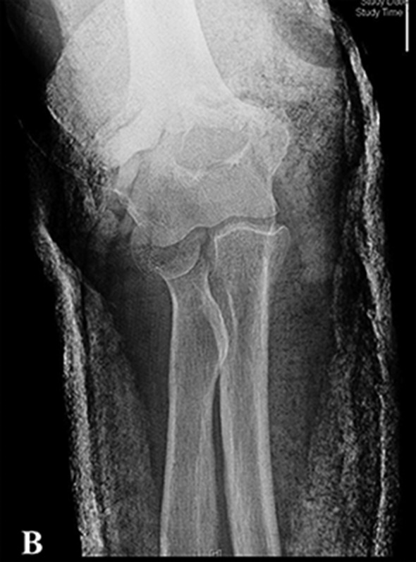
Figs. 1-A and 1-B Lateral (Fig. 1-A) and anteroposterior (Fig. 1-B) radiographs typically provide sufficient information for the diagnosis and treatment of radial head fractures.
Fig. 1-C.

Fig. 1-D.

Figs. 1-C and 1-D Lateral (Fig. 1-C) and medial (Fig. 1-D) views of the elbow with 3-dimensional CT reconstructions can provide useful information to characterize a radial head fracture and may also be valuable for preoperative planning.
Fig. 1-E.

Fig. 1-F.

Figs. 1-E and 1-F Postoperative lateral (Fig. 1-E) and anteroposterior (Fig. 1-F) radiographs demonstrate appropriate implant size. The medial ulnohumeral joint space is symmetric on the anteroposterior radiograph with no evidence of varus alignment of the elbow.
Fig. 1-G.

Fig. 1-H.

Figs. 1-G and 1-H Lateral (Fig. 1-G) and anteroposterior (Fig. 1-H) radiographs made 2 years postoperatively demonstrate that the radial head prosthesis remains in good alignment. There is radiographic evidence of mild stem lucency.
Step 2: Operating Room Setup and Patient Positioning
Perform proper operating room setup and patient positioning, as they are required to gain access to all affected structures around the elbow in a safe and efficient manner.
Place the patient in the supine position on the operating table with a bump under the scapula.
Administer general and/or regional anesthesia.
Perform a fluoroscopic examination of the elbow with the patient under anesthesia to check the functional integrity of the medial collateral ligament (MCL) and the LCL.
Administer prophylactic intravenous antibiotics prior to the skin incision and tourniquet inflation.
Prepare and drape the arm in a free manner with a stockinette over the hand.
Use a sterile tourniquet on the upper arm.
Place the involved arm over a padded bolster on the patient’s chest during the surgical exposure.
Step 3: Approach
Make a midline posterior skin incision with development of a full-thickness lateral fasciocutaneous flap or use a direct lateral incision; the deep interval is determined on the basis of the integrity of the LCL.
With the elbow flexed over the patient’s chest, perform a midline posterior skin incision just lateral to the tip of the olecranon. This is intended to minimize injury to cutaneous nerves and to provide better cosmesis than a lateral incision (Fig. 2).
Develop a full-thickness lateral fasciocutaneous flap and elevate it laterally, beginning at the subcutaneous border of the ulna distally and the triceps fascia proximally. Elevate the flap off the deep fascia approximately 3 cm anterior to the lateral epicondyle (Fig. 3).
A medial flap can also be developed to address medial-sided pathology in complex elbow injuries, but this is not commonly required.
The selection of the deep interval depends on the status of the LCL. When it is found to be intact during initial fluoroscopic examination under anesthesia, use a common extensor tendon split. This interval allows for better access to the radial head and preservation of the LUCL13 (Fig. 4).
When the LCL is found to be disrupted, use the Kocher interval between the anconeus and the extensor carpi ulnaris. The Kocher interval allows for better access to the LUCL for repair.
Carry out the deep surgical approach with the forearm held in pronation to protect the posterior interosseous nerve (PIN) by moving it in a more distal and ulnar direction14,15.
When the LCL is found to be intact, expose the radial head by incising the deep fascia at the mid-axis of the radial head, thereby staying anterior to the LUCL and helping to preserve elbow stability. Elevate the extensor muscles anteriorly off the lateral epicondyle and off the joint capsule. Take care not to elevate the origin of the LUCL off the lateral epicondyle. Incise the radial collateral ligament, joint capsule, and annular ligament to gain access to the radial head. Leave the anconeus intact as the LUCL lies underneath its anterior margin. The capsule and the extensor tendon origin may be elevated off the lateral supracondylar ridge of the humerus for additional exposure.
The LCL is often disrupted with comminuted radial head fractures and concomitant elbow dislocations6,16,17. In these instances, utilize the Kocher interval. Once through the fascia between the anconeus and the extensor carpi ulnaris, a bare lateral epicondyle may be present from avulsion of the lateral ligament and extensor muscles. Elevate the extensor muscles off the LUCL posteriorly and the joint capsule anteriorly. Perform the capsulotomy anterior to the LUCL and elevate the tissues anteriorly off the lateral supracondylar ridge for additional exposure, if needed (Fig. 5).
Fig. 2.

The involved arm is placed over the chest with a padded bolster. A midline posterior skin incision is utilized. It is intended to minimize potential injury to cutaneous nerves and provide better cosmesis than a lateral incision.
Fig. 3.

A full-thickness lateral fasciocutaneous flap is developed and elevated laterally. The flap is elevated off the deep fascia of the forearm and off the triceps fascia approximately 3 cm anterior to the lateral epicondyle.
Fig. 4.

Illustration demonstrating the use of an extensor tendon split for the deep interval when the LUCL is thought to be intact. The radial collateral ligament, joint capsule, and annular ligament are incised to gain access to the radial head. The anconeus is left intact as the LUCL lies deep to its anterior margin. (Image courtesy of Wright Medical. Reproduced with permission.)
Fig. 5.

When the LCL is found to be disrupted, the Kocher interval between the anconeus and extensor carpi ulnaris is utilized. Once through the fascia between the anconeus and extensor carpi ulnaris, a bare lateral epicondyle may be present from avulsion of the lateral ligament complex and the extensor origin. The fractured radial head (plus sign) and the disrupted LCL (arrow) are identified.
Step 4: Radial Head Excision
Remove and preserve all fragments of the radial head for implant sizing.
Carefully remove and collect the fragments of the radial head. Reassemble the radial head on the back table to ensure all fragments are accounted for.
An image intensifier can be used if there is difficulty locating all fragments.
Resect a minimal amount of radial neck at a right angle to the medullary canal of the radial neck to ensure a smooth surface for load transfer to the implant.
Use copious irrigation to remove any remaining intra-articular debris.
Evaluate and treat associated chondral and osseous injuries to the capitellum, coronoid, and olecranon accordingly.
Step 5: Implant Sizing
Implant a prosthesis that closely replicates the dimensions of the native radial head, which is the primary goal of the procedure.
Use the native head as a template, as it is a reliable method to determine correct radial head implant size. Preoperative radiographic templating of the contralateral normal radial head can be used in the setting of substantial bone loss.
Piece together the fragmented radial head to determine the height (thickness) and diameter of the implant. The radial head is ovoid and not circular in shape. The optimal size of the radial head implant is best estimated by measuring the minor diameter of the native radial head. The major diameter is typically 2 mm wider than the minor diameter (Fig. 6).
Radial head thickness may not be uniform around its circumference; revision of the neck cut or fracture line may be required. An implant that is selected on the basis of the thickest portion of the radial head will rest on the proximal extent of the radial neck, leading to overlengthening of the radius18 (Fig. 7).
It is recommended that at least 60% of the native radial neck be in contact with the implant to prevent implant subsidence and instability of the stem in the radial neck. If this is not the case, make the radial neck cut more distal and use a plus-sized stem. Do not upsize the head thickness to make up the difference, as this will cause the radial head to articulate incongruently with the lesser sigmoid notch18.
If the native radial head is between sizes, select the smaller implant size.
In the original article, a modular radial head implant system (Evolve; Wright Medical Technology) was utilized. This system offers multiple head diameters and head thicknesses and a variety of stem sizes. There are also a variety of stem heights to accommodate for potential fracture extension into the proximal neck. Each head can be combined with any of the stems, creating a multitude of combinations.
Fig. 6.

The native radial head has an elliptical shape. Select the minor rather than the major diameter when determining the size of the radial head prosthesis. This will most closely replicate the diameter of the articular dish rather than the outer diameter of the radial head. (Image courtesy of Wright Medical. Reproduced with permission.)
Fig. 7.

Selection of the height of the prosthesis should be based on the thickness of the native radial head. (Image courtesy of Wright Medical. Reproduced with permission.)
Step 6: Stem Broaching
Sequentially broach the canal until good cortical contact is achieved and undersize the definitive stem by 1 mm to allow implant movement within the canal and appropriate articulation with the capitellum.
Deliver the radial neck laterally using a Hohmann retractor carefully placed around the posterior aspect of the proximal radial neck (Fig. 8).
Never place a retractor anteriorly over the radial neck because of the risk of injury to the PIN.
Use the starter awl to create an opening in the medullary canal.
Then use broaches sequentially to ream the canal until good cortical contact is achieved. It is not necessary to aggressively broach the canal as the definitive implant will be undersized.
Select the stem collar height by placing the trial stem into the trial head to compare the total height with that of the native radial head that was excised (Fig. 9).
Use a neck rasp to smooth the neck cut, ensuring that it is at 90° to the neck.
Insert a trial stem 1 mm smaller than the final broach in the canal and insert the selected trial head.
Downsize the definitive stem by 1 mm to allow the circular, nonanatomically shaped implant to move within the canal and precisely align with the capitellum during range of motion (Fig. 10).
Fig. 8.

To facilitate exposure to the radial neck for stem broaching, a Hohmann retractor (arrow) is placed carefully around the posterior aspect of the radius to deliver it laterally. Avoid placing a retractor anteriorly as this places the PIN at risk of injury.
Fig. 9.

Selection of the stem collar height is performed by placing the trial stem into the trial head to compare the total height with that of the native radial head that was excised. The height of the radial head prosthesis should closely replicate the height of the native head in order to ensure concentric articulation of the radial head with the lesser sigmoid notch. (Image courtesy of Wright Medical. Reproduced with permission.)
Fig. 10.

The definitive stem is downsized by 1 mm to allow the circular, nonanatomically shaped implant to rotate within the canal to improve radiocapitellar articulator tracking.
Step 7: Insertion of Trial Components and Final Radial Head Implant
With the selected trial in place, assess the radial head diameter, height, and articular congruency.
With the trial components inserted, assess the implant tracking both visually and radiographically.
Assess appropriate implant height with the forearm in pronation to compensate for the lateral instability induced by the injury and the surgical approach. The trial head should articulate congruently with the most proximal margin of the lesser sigmoid notch, which is usually 2 mm distal to the tip of the coronoid process.
Perform a fluoroscopic evaluation to ensure the medial ulnohumeral joint space is symmetric. The radiographic appearance of the lateral ulnohumeral joint space is often asymmetric and is not a reliable indicator of implant size7.
A prosthesis that is too large will result in varus alignment of the elbow.
Take the elbow through a range of motion to ensure proper tracking. If maltracking of the prosthesis is noted, trial a smaller stem diameter to ensure that the articulation of the radial head and capitellum is optimal and not dictated by the orientation of the stem in the proximal aspect of the radius.
One advantage of the modular implant system over a monoblock radial head implant (where the head is fixed to the stem) is that it allows implantation of the stem first, followed by placement of the head into the stem. This can substantially reduce the exposure needed to insert the implant compared with a monoblock system19. In most cases, however, the definitive implant is assembled on the back table prior to implantation.
Remove the trial implants and insert the definitive implants. Take the elbow through a range of motion and reevaluate articular tracking (Fig. 11).
Fig. 11.

Selection of an appropriately sized implant allows for proper articulation with the capitellum.
Step 8: Closure and Repair of the LCL
Ensure proper repair of the LCL as it is essential to maintaining or restoring elbow stability.
If the LCL is intact, repair the capsulotomy with number-1 braided, absorbable sutures in a figure-of-8 manner. The extensor fascia is closed with similar sutures.
-
If the LCL and extensor muscle origin have been completely detached either through initial injury or surgical exposure, repair the LCL using nonabsorbable transosseous drill-holes through the lateral epicondyle. Alternatively, use a suture anchor.
-
◦
To find the isometric point on the lateral epicondyle, envision the capitellum as a circle and make a 2-mm drill-hole in the center of that circle. Make 1 drill-hole posterior and 1 anterior to the lateral supracondylar ridge.
-
◦
Use a number-2 nonabsorbable braided suture to whip-stitch the posterior aspect of the LUCL in a locking Krackow fashion. Continue the whip-stitch on the anterior aspect of the LCL, including the annular ligament and the radial collateral ligaments. When passing these stitches through the anterior aspect of the LUCL, make sure that they whip around the stitches placed in the posterior aspect of the LUCL so that they do not tear out (Figs. 12-A and 12-B).
-
◦
Repeat these steps to repair the forearm fascia and Kocher interval.
-
◦
Shuttle these 4 suture ends through the drill-holes using shuttling sutures or a suture retriever. Then tie them over the bone bridge on the lateral supracondylar ridge (Fig. 13). Alternatively, place 2 drill-holes posteriorly and a 2-hole plate or a cortical button on the bone so that the sutures do not cut out.
-
◦
Position the elbow in 30° of flexion, slight valgus, and mid-pronation while the sutures are tightened.
-
◦
Take the elbow again through a range of motion, carefully examining stability in pronation, supination, and neutral rotation.
Forearm pronation has been found to improve the stability of the LCL-deficient elbow20.
Supination has been found to improve stability in the MCL-deficient elbow21.
For patients who have an associated elbow dislocation, consider repair of the MCL and flexor pronator origin if the elbow subluxates at 60° of extension19.
Close the subcutaneous layer with 3-0 absorbable sutures and the skin with 3-0 nylon sutures in a vertical mattress pattern.
Immobilize the elbow in an above-the-elbow fiberglass back slab at 90° of flexion with the forearm in neutral rotation for 1 week.
Figs. 12-A and 12-B Repair and closure of the LUCL and forearm fascia.
Fig. 12-A.

The LUCL (asterisk) is whip-stitched using a number-2 nonabsorbable suture.
Fig. 12-B.

The posterior aspect of the forearm fascia has been whip-stitched (black arrow) using a number-2 nonabsorbable suture. Using the isometric point (white arrow) on the lateral epicondyle, a pair of 2-mm drill-holes is placed anterior and posterior to the lateral supracondylar ridge to shuttle the sutures, which were previously passed through the LUCL (asterisk) and through the extensor fascia.
Fig. 13.

Both the LUCL suture tails and the forearm fascia suture tails have been shuttled through the drill- holes and tied over the bone bridge of the lateral supracondylar ridge (arrow).
Step 9: Postoperative Protocol
Postoperative rehabilitation depends on the status of the collateral ligaments.
For patients with an intact LCL and MCL, the forearm is held in neutral rotation. Active range of motion is begun within the first week. The elbow is rested in a collar and cuff between exercises until comfortable. A progressive nighttime extension splint is used for 12 weeks to regain extension.
For patients who have had an LCL repair, active flexion-extension is performed with the forearm in pronation only. Extension in supination is avoided for 6 weeks in order to prevent posterolateral rotatory instability. Pronation and supination are only performed in flexion to minimize stress on the LCL. A resting splint is used for 3 to 6 weeks with the elbow maintained at 90° and the forearm in pronation. Static progressive nighttime extension splinting is begun at 6 weeks once ligamentous healing is thought to be adequate.
For patients with residual medial instability, the same protocol is initiated as for lateral instability, except that the forearm is maintained in supination. If both collateral ligaments are torn, elbow rehabilitation is performed with the forearm in neutral rotation.
Patients are given indomethacin (25 mg) 3 times a day for 3 weeks to decrease postoperative pain, reduce swelling, and potentially lower the rate of heterotopic ossification. This is given in conjunction with a proton pump inhibitor for gastric protection.
Results
In a review of the cases of 55 patients at a mean follow-up of 8 years after radial head arthroplasty with a smooth-stemmed modular metallic prosthesis, Marsh et al.9 demonstrated that good clinical outcomes were sustained compared with those in short-term series. While radiographic stem lucencies were common (25 patients), most patients had favorable subjective and objective clinical outcomes. Subgroup analysis on a subset of patients who had been previously described at short-term follow-up by Grewal et al.22 demonstrated no apparent functional deterioration from short-term to longer-term follow-up. Importantly, at the time of the final follow-up, no patient had had the implant removed or revised. Radial head replacement for unreconstructible radial head fractures with a smooth-stemmed modular metallic radial head implant is a safe and reliable treatment option8-10,22.
Pitfalls & Challenges
In patients with collateral ligament injuries, be cognizant to not overlengthen the radius with a larger radial head height in order to address subjective findings of elbow instability. An appropriately sized implant is determined using the native radial head. Any residual instability following implant insertion should be addressed through soft-tissue repair of the LCL.
In patients with disruption of the interosseous membrane, proximal migration of the radius may be evident, and the surgeon should be cognizant of this as it can influence sizing of the implant.
Be aware not to extend the dissection distal to the bicipital tuberosity as the PIN is at risk of injury.
Osteoarthritis of the capitellum can occur from the initial injury, from overstuffing the joint with an excessively thick implant, or from persistent instability. The arthritis can eventually progress to the ulnohumeral joint. Treatment options include open and arthroscopic debridement as well as removal of the radial head prosthesis. With advanced arthritis, a total elbow arthroplasty may be required.
Stiffness is frequently seen following unreconstructible radial head fractures and complex elbow dislocations. Capsular contracture resulting in loss of terminal extension is quite common. Fortunately, most patients respond to passive stretching and progressive static splinting under the supervision of a physiotherapist. For those in whom nonoperative treatments fail, arthroscopic or open capsular release may be required.
Footnotes
Published outcomes of this procedure can be found at: J Bone Joint Surg Am. 2016 Apr 6;98(7):527-35
Disclosure: The authors indicated that no external funding was received for any aspect of this work. On the Disclosure of Potential Conflicts of Interest forms, which are provided with the online version of the article, one or more of the authors checked “yes” to indicate that the author had a relevant financial relationship in the biomedical arena outside the submitted work and “yes” to indicate that the author had a patent issued for the device that is the subject of this article.
References
- 1. Mason ML. Some observations on fractures of the head of the radius with a review of one hundred cases. Br J Surg. 1954. September;42(172):123-32. [DOI] [PubMed] [Google Scholar]
- 2. Hotchkiss RN, Weiland AJ. Valgus stability of the elbow. J Orthop Res. 1987;5(3):372-7. [DOI] [PubMed] [Google Scholar]
- 3. Knight DJ, Rymaszewski LA, Amis AA, Miller JH. Primary replacement of the fractured radial head with a metal prosthesis. J Bone Joint Surg Br. 1993. July;75(4):572-6. [DOI] [PubMed] [Google Scholar]
- 4. Morrey BF, An KN. Articular and ligamentous contributions to the stability of the elbow joint. Am J Sports Med. 1983. Sep-Oct;11(5):315-9. [DOI] [PubMed] [Google Scholar]
- 5. Sellman DC, Seitz WH, Jr, Postak PD, Greenwald AS. Reconstructive strategies for radioulnar dissociation: a biomechanical study. J Orthop Trauma. 1995;9(6):516-22. [DOI] [PubMed] [Google Scholar]
- 6. McKee MD, Pugh DMW, Wild LM, Schemitsch EH, King GJW. Standard surgical protocol to treat elbow dislocations with radial head and coronoid fractures. Surgical technique. J Bone Joint Surg Am. 2005. March;87(Pt 1)(Suppl 1):22-32. [DOI] [PubMed] [Google Scholar]
- 7. King GJW. Management of comminuted radial head fractures with replacement arthroplasty. Hand Clin. 2004. November;20(4):429-41, vi. [DOI] [PubMed] [Google Scholar]
- 8. Harrington IJ, Sekyi-Otu A, Barrington TW, Evans DC, Tuli V. The functional outcome with metallic radial head implants in the treatment of unstable elbow fractures: a long-term review. J Trauma. 2001. January;50(1):46-52. [DOI] [PubMed] [Google Scholar]
- 9. Marsh JP, Grewal R, Faber KJ, Drosdowech DS, Athwal GS, King GJ. Radial head fractures treated with modular metallic radial head replacement: outcomes at a mean follow-up of eight years. J Bone Joint Surg Am. 2016. April 6;98(7):527-35. [DOI] [PubMed] [Google Scholar]
- 10. Moro JK, Werier J, MacDermid JC, Patterson SD, King GJ. Arthroplasty with a metal radial head for unreconstructible fractures of the radial head. J Bone Joint Surg Am. 2001. August;83(8):1201-11. [DOI] [PubMed] [Google Scholar]
- 11. Kocher T. Textbook of operative surgery. 3rd ed. London: Adams and Charles Black; 1911. [Google Scholar]
- 12. Cheung EV, Steinmann SP. Surgical approaches to the elbow. J Am Acad Orthop Surg. 2009. May;17(5):325-33. [DOI] [PubMed] [Google Scholar]
- 13. Desloges W, Louati H, Papp SR, Pollock JW. Objective analysis of lateral elbow exposure with the extensor digitorum communis split compared with the Kocher interval. J Bone Joint Surg Am. 2014. March 5;96(5):387-93. [DOI] [PubMed] [Google Scholar]
- 14. Strachan JC, Ellis BW. Vulnerability of the posterior interosseous nerve during radial head resection. J Bone Joint Surg Br. 1971. May;53(2):320-3. [PubMed] [Google Scholar]
- 15. Diliberti T, Botte MJ, Abrams RA. Anatomical considerations regarding the posterior interosseous nerve during posterolateral approaches to the proximal part of the radius. J Bone Joint Surg Am. 2000. June;82(6):809-13. [DOI] [PubMed] [Google Scholar]
- 16. Chan K, King GJW, Faber KJ. Treatment of complex elbow fracture-dislocations. Curr Rev Musculoskelet Med. 2016. June;9(2):185-9. [DOI] [PMC free article] [PubMed] [Google Scholar]
- 17. Josefsson PO, Johnell O, Wendeberg B. Ligamentous injuries in dislocations of the elbow joint. Clin Orthop Relat Res. 1987. August;221:221-5. [PubMed] [Google Scholar]
- 18. Athwal GS, Frank SG, Grewal R, Faber KJ, Johnson J, King GJ. Determination of correct implant size in radial head arthroplasty to avoid overlengthening: surgical technique. J Bone Joint Surg Am. 2010. September;92(Suppl 1 Pt 2):250-7. [DOI] [PubMed] [Google Scholar]
- 19. King GJ, Patterson SD. Metallic radial head arthroplasty. Tech Hand Up Extrem Surg. 2001. December;5(4):196-203. [DOI] [PubMed] [Google Scholar]
- 20. Dunning CE, Zarzour ZD, Patterson SD, Johnson JA, King GJ. Muscle forces and pronation stabilize the lateral ligament deficient elbow. Clin Orthop Relat Res. 2001. July;388:118-24. [DOI] [PubMed] [Google Scholar]
- 21. Armstrong AD, Dunning CE, Faber KJ, Duck TR, Johnson JA, King GJ. Rehabilitation of the medial collateral ligament-deficient elbow: an in vitro biomechanical study. J Hand Surg Am. 2000. November;25(6):1051-7. [DOI] [PubMed] [Google Scholar]
- 22. Grewal R, MacDermid JC, Faber KJ, Drosdowech DS, King GJW. Comminuted radial head fractures treated with a modular metallic radial head arthroplasty. Study of outcomes. J Bone Joint Surg Am. 2006. October;88(10):2192-200. [DOI] [PubMed] [Google Scholar]