

Overview
Introduction
An alternative method to external fixation for the treatment of unstable anterior pelvic ring injuries, termed the pelvic bridge technique, provides equivalent results with fewer complications and is performed using occipital cervical rods subcutaneously, with fixation into the iliac wings and parasymphyseal bone.
Indications & Contraindications
Step 1: Preoperative Planning
For preoperative planning, review the appropriate imaging, including radiographs and computed tomography (CT) scans, to mesh the findings on imaging to the clinical picture of the patient and ensure that the patient meets operative criteria and that none of the contraindications are present.
Step 2: Patient Positioning
Position the patient to facilitate anterior and posterior fixation.
Step 3: Approach
Make the incisions necessary to expose the osseous contour where fixation will be utilized.
Step 4: Contouring the Plate-Rod Construct
Carefully contour the plate-rod construct, which is necessary to minimize postoperative complications.
Step 5: Passing the Plate-Rod Construct
Use care when inserting the rod as doing so will help to avoid neurovascular complications.
Step 6: Achieving Adequate Reduction
To recreate pelvic stability, the pelvic ring needs to heal in as close to anatomic position as possible and there are multiple methods that help to obtain an adequate reduction.
Step 7: Fracture Fixation
Multiple constructs may be used to stabilize the anterior pelvic ring, but the fundamental principle is to attach the 2 hemipelves to achieve stability, and the location where fixation can be achieved depends on the fracture pattern.
Step 8: Wound Closure
Ensure meticulous closure to reduce the chance of infection and achieve appropriate soft-tissue coverage over hardware.
Step 9: Rehabilitation
Early mobilization is a fundamental goal of this procedure, but the time to full weight-bearing is dependent on fracture characteristics and healing.
Results
Anterior pelvic internal fixation (APIF) using the pelvic bridge technique has been demonstrated to have significantly fewer complications than APEF2.
Pitfalls & Challenges
Introduction
An alternative method to external fixation for the treatment of unstable anterior pelvic ring injuries, termed the pelvic bridge technique, provides equivalent results with fewer complications and is performed using occipital cervical rods subcutaneously, with fixation into the iliac wings and parasymphyseal bone.
Pelvic ring injuries represent between 0.3% and 6% of all fractures, but are much more common in patients with polytrauma (20%)1. Anterior pelvic external fixation (APEF) is a common method used to stabilize a disrupted pelvic ring, with the proven benefits of reducing morbidity and mortality associated with unstable pelvic fractures. Furthermore, it is often used in the subacute setting to augment stability after posterior reduction and fixation has been applied to the pelvis. Although fixation is technically simple, complication rates for APEF have been reported to range from 10% to 62% and include pin-site infections, fixator loosening, neurologic compromise, and fixator pin impingement on the skin1. Additionally, APEF often causes discomfort and immobility for the patient and increases nursing care requirements. These problems may be particularly prevalent in obese patients with polytrauma.
We developed an alternative method of stabilizing the anterior aspect of the pelvis that provides equivalent stability, while reducing the complications associated with APEF, using a subcutaneous pelvic bridge technique2. As a general principle, the pelvic bridge can be used as a substitute for the APEF. In a stepwise progression, the procedure involves preoperative planning, appropriate patient positioning, making the incisions, bluntly creating a tunnel between the 2 incisions that is parallel and superficial to the inguinal ligament, contouring the plate-rod construct, inserting the construct through the subcutaneous tunnel, reducing the pelvis, and applying pedicle screw fixation into the parasymphyseal bone and screw fixation into the ilium, followed by wound closure.
It is important to note that the original description of the procedure involved using pelvic reconstruction plates. Extensive bone and skin ingrowth could make removal of this system challenging so the senior author changed to an occipitocervical spinal plate-rod implant to better facilitate ease of removal after pelvic healing had been achieved. The pelvic bridge can be applied to patients of any type of body habitus.
Indications & Contraindications
Indications
Unstable anterior pelvic ring.
To enhance stability of the pelvis after posterior fixation.
To avoid pelvic external fixation.
To increase stability to promote early ambulation.
Obese patients.
Contraindications
Iliac wing dissociation.
Degloving or open wounds over the iliac wing.
Open pelvic injury with peritoneal contamination.
Injuries requiring rapid stabilization in a hemodynamically unstable patient.
Simple pubic diastasis.
It should not be used as a sole treatment for anterior and posterior instability.
Step 1: Preoperative Planning
For preoperative planning, review the appropriate imaging, including radiographs and computed tomography (CT) scans, to mesh the findings on imaging to the clinical picture of the patient and ensure that the patient meets operative criteria and that none of the contraindications are present.
Review the imaging to decide on the operative plan as would be done for any pelvic fracture (Fig. 1).
Prioritize the posterior pelvic ring so that it is addressed first. This article will not emphasize posterior fixation options.
For the pelvic bridge, specifically look at the iliac crest and parasymphyseal pubic rami to ensure adequate opportunity for fixation. Ensure that the iliac crest is attached to the posterior part of the pelvis such that anterior fixation can augment posterior fixation (Video 1).
Have a pelvic model available and draw out fracture lines and plan hardware position as one’s experience necessitates. The pelvic bridge is not a procedure for inexperienced trauma surgeons or surgeons not intimately familiar with the anatomy of the pelvis.
Fig. 1.

Inlet (Fig. 1-A) and outlet (Fig. 1-B) radiographs demonstrate bilateral fractures of the sacral ala, bilateral superior pubic rami fractures, a comminuted fracture of the right aspect of the symphysis pubis, and a displaced fracture of the right inferior pubic ramus.
Video 1.
Minimizing neurovascular compromise.
Step 2: Patient Positioning
Position the patient to facilitate anterior and posterior fixation.
Place the patient supine and centrally on a radiolucent table (i.e., a Mizuho OSI flat top or Jackson table). Elevate the sacrum with a bolster. Our preference is to use the Lower Extremity PROP (Bone Foam) if sacroiliac screws are planned as it allows the surgeon to drop his or her hand closer to the floor for the correct screw trajectory.
Keep the arms of the patient out to the side on arm boards, abducted no more than 90°.
Prepare and drape the surgical field that extends from the lower ribs to the proximal part of the thigh. Shave hair from the pubic area and isolate the groin with an occlusive dressing.
If traction and/or manipulation of the lower extremities is required to achieve reduction, they too can be included in the field.
Confirm that it is possible to obtain the necessary fluoroscopic imaging, including anteroposterior pelvic, inlet, outlet, and Judet views.
If the patient requires a bilateral iliac construct, position the C-arm on the side that is suspected to reduce more easily. The C-arm should approach the table at a 90° angle to ensure the ability to obtain the necessary views.
Step 3: Approach
Make the incisions necessary to expose the osseous contour where fixation will be utilized.
Incise from the anterior superior iliac spine (ASIS) extending posteriorly along the crest for 5 cm. Use a combination of scalpel and cautery to dissect down to the external oblique fascia. Carefully elevate the musculature directly off the crest with cautery to create fixation for the plate-rod construct.
Centrally, use a Pfannenstiel type of incision centered over the palpable pubic tubercles. Make a horizontal incision of 6 to 8 cm centered on the pubic symphysis. Use cautery or a scalpel to dissect down the rectus abdominis fascia. Palpate the pubic symphysis and tubercles. Cautery can be used to identify and mark positions for insertion of polyaxial screws along the anterior superior pubic rami and parasymphyseal area (Fig. 2, Video 2).
After the medial and lateral windows are established, create a subcutaneous tunnel using a periosteal surfer or a small Cobb elevator. The surfer is used to bluntly dissect parallel and superficial to the inguinal ligament. It can be inserted via the medial and lateral windows. Care must be taken, especially if there is fascial disruption secondary to the pelvic injury, not to enter the abdomen. Digital palpation as well as a CT review can assist with determining if there are any fascial rents that are a cause for concern. Additionally, right angle retractors can be used to elevate the subcutaneous fat, thus allowing direct visualization of the tunnel from the medial and lateral windows while the periosteal surfer is used.
Take care not to create tunnels that stray cephalad or caudad to the inguinal ligament. Additionally, ensure creation of only 1 tunnel to facilitate hardware passage.
Dissection is complete when the periosteal surfer is easily passed between windows.
Despite variations in pelvic anatomy and width of pelvic brims, prior work has shown that precontoured fixators did not violate any pelvic neurovascular structures when using this recommended application of the pelvic bridge3. The spermatic cord or round ligament was directly visualized and easily avoided using our application technique. The iliohypogastric nerve and ilioinguinal nerve were found to be protected by the abdominal musculature for most of their course, with the pelvic bridge plates remaining inferior and resting superficial to their branches at a mean distance from the fixator of 1.5 cm (range, 1.2 to 1.8 cm) and 2.1 cm (range, 0.9 to 4 cm) for the iliohypogastric and ilioinguinal nerves, respectively3. The lateral femoral cutaneous nerve was found to course safely posterior to the inguinal ligament; thus, the nerve was bridged by the internal spanning fixation without visualized disruption, impingement, or violation (mean distance from the fixator of 1.5 cm [range, 0.6 to 4 cm]). Lastly, the femoral nerve, artery, and vein were together at a safe distance (mean, 2.2 cm [range, 0.8 to 3.7 cm]) from risk of compression by the fixator (Fig. 3)3.
Fig. 2.
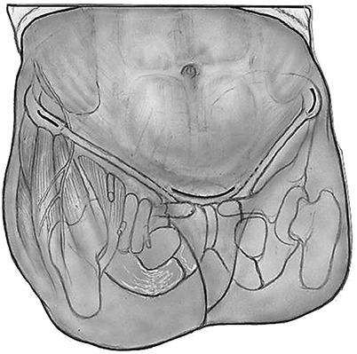
Illustration demonstrating bilateral incisions over the anterior superior iliac spine (ASIS) for a traditional ilioinguinal approach, as well as a Pfannenstiel type of incision over the pubic symphysis.
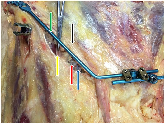
Fig. 3.

Cadaveric specimen demonstrating another type of internal pelvic fixation (black arrow), its 2 points of fixation (green arrows), and the proximity of its pedicle screws to the lateral femoral cutaneous nerve (LFCN; red arrow). The pelvic bridge bilateral construct (yellow arrows) mirrors static anatomic structures, has 4 points of fixation (purple arrows), and maintains a safe distance from the LFCN.
Video 2.
Approach.
Step 4: Contouring the Plate-Rod Construct
Carefully contour the plate-rod construct, which is necessary to minimize postoperative complications.
Instrumentation used in our practice is the Synthes occipital cervical plate-rod construct from its fusion system (4.0 mm) with Synthes Synapse System polyaxial screws (4.5 mm) and cross-links for increased stability (Synthes Spine). This is not a U.S. Food and Drug Administration-approved use of this construct, and as such it must be made clear that this is an off-label use.
Contouring is patient-specific. However, there are some basic principles to follow. The plate is contoured with a gentle curve, such that it accommodates the curvature of the iliac crest. Where the plate meets the rod, a bend is made 30° toward the midline and 10° caudal to align with the inguinal ligament. Next, measure the distance from the ASIS to the pubic tubercle. Use this distance to determine proper placement for the second rod bend (typically around 60°) at the edge of the Pfannenstiel incision, such that the rod parallels the anterior-superior border of the superior pubic rami.
The construct may need to be recontoured until it aligns with the inguinal ligament. Ensure that the contour is not tight to the inguinal ligament to avoid compression of neurovascular structures (Video 3).
Video 3.
Contouring the plate-rod construct.
Step 5: Passing the Plate-Rod Construct
Use care when inserting the rod as doing so will help to avoid neurovascular complications.
Insert a digit into the previously dissected tunnel from the medial to the lateral window and place the tip of the contoured rod on the end of that finger.
Push the rod from lateral to medial while guiding it along and superficial to the inguinal ligament, protecting the neurovascular bundle located deep to the ligament.
Place the plate on the iliac wing and assess the contour. Temporary screw fixation in the iliac wing will help in assessing the reduction. Use fluoroscopy and direct visualization to determine the adequacy of the contour. If it does not fit closely to the iliac crest and superior pubic rami while the pelvis is reduced, remove, recontour, and reinsert as described. The rod should parallel the inguinal ligament but not compress it or any of the underlying structures (Fig. 4, Video 4).
Fig. 4.
The superficial positioning of the pelvic bridge (green arrow) in relation to the inguinal ligament (black arrow) ensures a safe proximity to underlying neurovasculature, thus minimizing the risk of impingement on the femoral nerve (yellow arrow), artery (red arrow), and/or vein (blue arrow).
Video 4.
Passing the construct.
Step 6: Achieving Adequate Reduction
To recreate pelvic stability, the pelvic ring needs to heal in as close to anatomic position as possible and there are multiple methods that help to obtain an adequate reduction.
If the pelvic bridge is being used to augment a pelvis that has already been fixed posteriorly, then the reduction usually consists of simple manual compression of the iliac wings.
To control rotation and vertical translation, stronger reduction methods are required. Schanz pins can be inserted either into the crest just posterior to the plate fixation or in the supra-acetabular corridor with a small ancillary incision.
The pins can then be used as joysticks to control the 2 hemipelves to effect a reduction.
If more severe vertical malalignment that is resistant to the Schanz pin joysticks is encountered, use a distal femoral traction pin.
Step 7: Fracture Fixation
Multiple constructs may be used to stabilize the anterior pelvic ring, but the fundamental principle is to attach the 2 hemipelves to achieve stability, and the location where fixation can be achieved depends on the fracture pattern.
After appropriately contouring the plate-rod constructs and achieving reduction, apply fixation.
Initially place a single screw in the most medial hole, aiming down the iliac crest into the anterior column. Use the drill resistance as feedback to extrapolate appropriate intraosseous position. Depending on pelvic morphology, 50 to 100-mm screws are generally safely achievable. The screw trajectory is analogous to the Schanz pin trajectory in the application of an iliac crest-based external fixation device and thus should be familiar to all surgeons who treat pelvic fractures (Fig. 5). Placement of a single screw allows rotation around the screw for optimal plate positioning on the crest and pubis. Use fluoroscopy, specifically the parallel and perpendicular views of the iliac wing, to ensure appropriate position and trajectory (Video 5).
In a unilateral construct, 4.5-mm-diameter polyaxial screws are inserted into the pubic tubercle, aiming into the ipsilateral inferior ramus on both sides of the pubic symphysis in line with the rod construct and are fixed to the rod with the locking cap. The trajectories and lengths of these screws will be familiar to pelvic surgeons as they mimic those that are used to affix a plate above the pubic symphysis in a simple diastasis scenario. Generally, parasymphyseal screws are 30 to 50 mm long (Fig. 6).
If a bilateral construct is used, apply a plate-rod construct to the contralateral iliac crest and pass the construct to the midline as previously described. Each rod requires at least 1 polyaxial screw inserted into the contralateral pubic tubercle. However, 2 screws on each side of the pubic symphysis provide a stronger construct.
Overcrowding of polyaxial screws can be an issue. Additional screws can be inserted into the pubic bone off-axis with the rod and attached to it with rod extenders (Fig. 7).
For additional stability in bilateral constructs, rod connectors can be used between rods.
Once fixation around the pubic symphysis has been achieved, up to 3 more cortical screws can be inserted into the crest. We have found that, in most cases, 2 screws provide adequate fixation (Fig. 8).
Fig. 5.
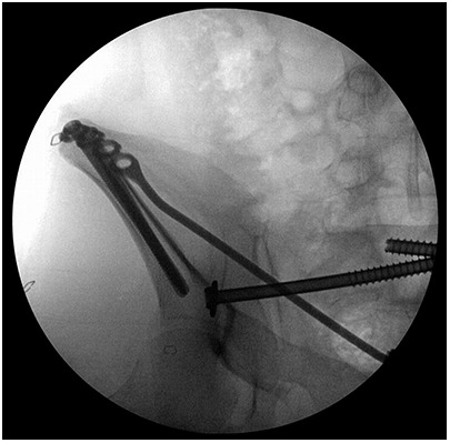
Intraoperative C-arm image demonstrating the medial and caudad trajectory of the 80 and 85-mm-long locking screws in the right iliac crest.
Fig. 6.
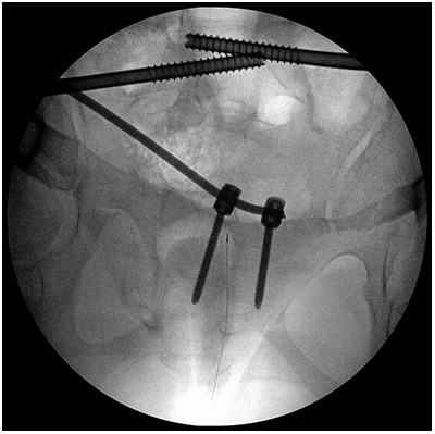
Intraoperative C-arm image demonstrating the trajectory of the 4.5-mm-diameter by 45-mm-long pedicle screws that are placed in each pubic tubercle to capture the rod.
Fig. 7.
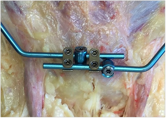
Bilateral pelvic bridge construct in a cadaveric specimen. Note the option for multiplanar placement of the pedicle screws in each pubic tubercle. The gold rod connectors add stability.
Fig. 8.
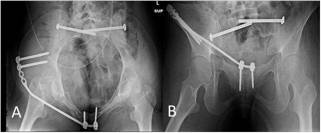
Postoperative inlet (Fig. 8-A) and outlet (Fig. 8-B) radiographs, made on postoperative day 12, demonstrating stable positioning of the unilateral pelvic bridge.
Video 5.
Screw placement.
Step 8: Wound Closure
Ensure meticulous closure to reduce the chance of infection and achieve appropriate soft-tissue coverage over hardware.
Irrigate wounds with normal saline solution. Reconfirm adequate hemostasis.
If bleeding is expected, 1 or 2 drains can be used, although generally they are not necessary. Ensure that the tail(s) of the drain(s) are in the dependent part of the wound. The Hemovac drains (Zimmer) are brought out of the skin cephalad and lateral to the incisions.
For the central wound, close the dead space and subcutaneous tissue with number-2.0 Vicryl sutures (Ethicon). Close the subcuticular layer with number-3.0 Monocryl sutures (Ethicon). Apply Dermabond (Ethicon) to the closed wound and reinforce with Steri-Strips (3M) if the wound is under any tension.
Island dressings can be applied.
Step 9: Rehabilitation
Early mobilization is a fundamental goal of this procedure, but the time to full weight-bearing is dependent on fracture characteristics and healing.
Postoperatively, the patients generally are allowed weight-bearing as tolerated, but this decision has more to do with the surgeon’s assessment of the posterior ring fixation. The patient can remain toe-touch weight-bearing for 6 weeks. There are no restrictions of hip motion during this time.
-
Removal of implants is our current practice, given the lack of long-term outcomes after this surgery. Implants could become difficult to remove or may irritate or compress soft tissues, for example.
Fig. 9.

Inlet (Fig. 9-A) and outlet (Fig. 9-B) radiographs, made 3 weeks after removal of the unilateral pelvic bridge, demonstrate healing of the right superior and inferior pubic rami fractures, the retained bilateral sacroiliac screws, and a symmetric pelvic ring.
Video 6.
Rehabilitation.
Results
Anterior pelvic internal fixation (APIF) using the pelvic bridge technique has been demonstrated to have significantly fewer complications than APEF2. As a group, we reported on the safety and results of the pelvic bridge procedure utilizing a pelvic reconstruction plate1. Additionally, 2 cadaveric anatomic studies have shown the safety of the pelvic bridge as it relates to the lateral femoral cutaneous nerve; ilioinguinal nerve; iliohypogastric nerve; femoral artery, vein, and nerve; and spermatic cord or round ligament3,4. Because the pelvic bridge superficially parallels static anatomic structures (iliac crest, inguinal ligament, and pubic symphysis), it is very unlikely to impinge on underlying neurovascular structures. This is an advantage compared with other subcutaneous anterior pelvic fixation techniques.
A case-control study that was published in 2012 included 48 patients (24 patients treated with APEF and 24 treated with APIF using pelvic reconstruction plates1. Although there were no significant differences between the APIF and APEF groups with respect to mechanism of injury, time from injury to surgery, time spent in the operating room, American Society of Anesthesiologists rating, and Injury Severity Score, a significant difference was detected between the rate of complications in the APIF group and that in the APEF group1. There were 3 observed complications in the APIF group, with all 3 occurring in 1 patient (4%) who had a superficial wound infection that was thought to be a stitch abscess. There were 15 complications observed in 9 patients (38%) in the APEF group. In addition, a significant difference was found between the groups with respect to chart documentation of pain at the surgical site that was noted during postoperative follow-up evaluations.
Significant differences were also found in the quality of the reduction postoperatively. The amount of vertical displacement at the final follow-up evaluation after treatment with APIF and APEF was 4.4 and 7.8 mm, respectively. No patient in the APIF group had a reduction that was not acceptable in terms of vertical displacement. However, 2 patients in the APEF group had a reduction that was not acceptable postoperatively, with the poor-quality reduction persisting until final follow-up in 1 patient with vertical displacement of 30 mm1.
Pitfalls & Challenges
We recognize that mandatory removal of hardware would be a relative drawback. However, many surgeons follow a convention of removing the APEF hardware (external fixator) in the operating room anyway, thus effectively negating the difference between the 2 techniques.
Additionally, it is likely that the pelvic bridge hardware does not need to be removed. In fact, most patients have not requested removal due to discomfort. The senior author advocates removal for several reasons: pressure over the hardware (i.e., on physical examination) can cause discomfort, and we do not know the potentially deleterious long-term consequence of leaving this construct in situ; in addition, this practice permitted a direct comparison to APEF for the purposes of our study.
Footnotes
Published outcomes of this article can be found at: Clin Orthop Relat Res. 2012;470:2116-23.
Investigation performed at the Department of Orthopaedic Surgery, University of Minnesota, Regions Hospital, St. Paul, Minnesota
Disclosure: One author (P.A.C.) receives institutional grant support from Stryker, DePuy-Synthes, AOTrauma, AONA, COTA, and OMeGA, and honoraria from AOTrauma, and is a shareholder in Bone Foams, Inc. The remaining authors (D.K.H., A.J.D., and E.D.) have nothing to declare. The authors indicated that no external funding was received for any aspect of this work. On the Disclosure of Potential Conflicts of Interest forms, which are provided with the online version of the article, one or more of the authors checked “yes” to indicate that the author had a relevant financial relationship in the biomedical arena outside the submitted work.
References
- 1. Cole PA, Gauger EM, Anavian J, Ly TV, Morgan RA, Heddings AA. Anterior pelvic external fixator versus subcutaneous internal fixator in the treatment of anterior ring pelvic fractures. J Orthop Trauma. 2012. May;26(5):269-77. [DOI] [PubMed] [Google Scholar]
- 2. Hiesterman TG, Hill BW, Cole PA. Surgical technique: a percutaneous method of subcutaneous fixation for the anterior pelvic ring: the pelvic bridge. Clin Orthop Relat Res. 2012. August;470(8):2116-23. [DOI] [PMC free article] [PubMed] [Google Scholar]
- 3. Moazzam C, Heddings AA, Moodie P, Cole PA. Anterior pelvic subcutaneous internal fixator application: an anatomic study. J Orthop Trauma. 2012. May;26(5):263-8. [DOI] [PubMed] [Google Scholar]
- 4. Reichel LM, MacCormick L, Dugarte AJ, Rizkala A, Graves S, Cole PA. Anterior pelvic internal fixation: an anatomic study comparing pelvic bridge to INFIX. Unpublished data. [DOI] [PubMed] [Google Scholar]