Abstract
Previously developed shape-memory polymer foams display fast actuation in water due to plasticization of the polymer network. The actuation presents itself as a depression in the glass-transition temperature when moving from dry to aqueous conditions; this effect limits the working time of the foam to 10 min when used in a transcatheter embolic device. Reproducible foams are developed by altering the chemical backbone, which can achieve working times of greater than 20 min. This is accomplished by incorporating isophorone diisocyanate into the foam, resulting in increased hydrophobicity, glass transitions, and actuation time. This delayed actuation, when compared with previous systems, allows for more optimal working time in clinical applications.
Keywords: actuation rate, hydrophobicity, polyurethanes, shape-memory polymers, working time
Graphical Abstract
1. Introduction
Shape-memory polymers (SMPs) are considered smart materials because they have the capability of switching between a primary and a secondary shape due to thermomechanical memory. [1–9] The SMP can be synthesized into a primary shape; when heated above a transition temperature (Ttrans), an SMP can be programmed via mechanical stimulus and set into a secondary shape during cooling. [2–5,10] Upon the input of an external stimulus, such as heat, the material will actuate to its original shape, thus demonstrating shape-memory behavior. [11,12] Our group focuses on developing polyurethane shape-memory polymers, specifically, as foams for their potential application in an embolic vascular device for aneurysm treatment. [6–8]
A recent review of alternative porous/foam SMP strategies in biomedical applications, such as scaffolds, sponges, and drug-delivery platforms, are elucidated elsewhere. [13] Aneurysms are a weakening of the blood vessel wall that result in ballooning of the area. [14,15] They affect about 3 to 5 million people in the United States and up to 300 000 people suffer from a ruptured aneurysm each year. [15] Aneurysm rupture results in a subarachnoid hemorrhage, which can lead to severe disability or even death. [16,17] Current endovascular treatments, such as Guglielmi Detachable Coils, are effective though they have limitations that result in aneurysm rupture and recanalization. [18,19] We aim to develop a shape-memory polymer foam embolic device that would be deliverable via catheter to the aneurysm space and would provide better occlusion and healing than the current treatments. We selected a polyurethane chemistry approach to SMP foam generation, as urethanes are well known for their biocompatibility, versatility, and tunable mechanical properties. [20–25] Previously, our group has developed aliphatic shape-memory polyurethane foams for use in embolic devices; however, a prominent issue with these systems has been the depression of the glass transition temperature (Tg) in aqueous environments.[7] Water molecules serve as plasticizing agents, enabling mobility of the polymer chains at reduced temperature. It has been shown that the effect in urethanes is due to interference of water with interchain hydrogen bonding. [7,26–28] This causes a significant decrease in the Tg, which results in premature foam actuation and a reduction in working time for the device. [29] In order to deliver the foam from the catheter to the aneurysm, the foam must maintain its secondary, programmed shape for a considerable length of time to ensure ease/completion of delivery. However, water plasticization may cause the foams to actuate too quickly in the catheter, presenting a hurdle in foam-over-coil delivery. Singhal et al. [7] synthesized SMP foams using various combinations of hexamethylene diisocyanate (HDI), trimethyl hexamethylene diisocyanate (TMHDI), hydroxypropylethylenediamine (HPED), and triethanolamine (TEA) to achieve a similar goal of increasing working time of the embolic device; however, those efforts attained ca. 10 min of working time before the SMP foam began to actuate.
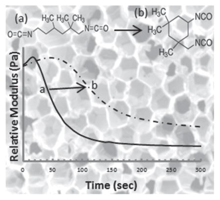
The goal our research in this study was to elongate the working time beyond 10 min by further increasing the hydrophobicity and glass transition, hence the actuation rate of the SMP foams, by incorporating isophorone diisocyanate (IPDI) into the foam chemistry. In this paper, we develop ultralow density SMP foams and determine their chemical and mechanical properties, as well as, study their actuation times in an aqueous environment (range: 4 to >20 min).
2. Materials and Methods
2.1. Synthesis and Postprocessing
N,N,N′,N′-Tetrakis(2-hydroxypropyl)ethylenediamine (HPED) (99%; Sigma–Aldrich), triethanolamine (TEA) (98%; Sigma–Aldrich), trimethyl-1,6-hexamethylene diisocyanate, 2,2,4- and 2,4,4-mixture (TMHDI) (TCI America Inc.), isophorone diisocyante (IPDI) (98%; Sigma–Aldrich), DC 198, DC 5943, T-131, and BL-22 (Air Products and Chemicals, Inc.), Enovate 245fa Blowing Agent (Honeywell International, Inc.), and deionized (DI) water (>17 MΩ cm purity; Millipore water purifier system; Millipore Inc.), phosphate buffered saline (1×) (0.0067 M PO4) (HyClone Laboratories, Inc.) were used as received.
SMP foam was synthesized using the three-step protocol mentioned in previous work. [6,7] First, an isocyanate (NCO) prepolymer was synthesized with appropriate molar ratios of HPED, TEA, TMHDI, and IPDI. These prepolymers were allowed to react for 2 d with a temperature ramp from room temperature to 50 °C and back to room temperature. Next, a hydroxyl (OH) mixture was blended with the remaining molar equivalents of HPED and TEA. This mixture also contained DI water, and catalysts. Finally, the NCO prepolymer and the OH mixture were combined in the foam cup along with surfactants, DC 198 and DC 5943, and Enovate. This mixture was allowed to mix in a FlackTek speedmixer (FlackTek, Inc., Landrum, SC) and poured in the foam bucket. The foam was allowed to cure at 90 °C for 20 min before being allowed to cool down to room temperature for further processing. Table 1 shows the weight percent of each component used for foam synthesis and Figure 1 shows the corresponding molecular structure of each monomer.
Table 1.
Composition of foams using trimethylhexamethylene diisocyanate (TMHDI) and isophorone diisocyanate (IPDI) for the isocyanate component of the urethane foam. Three foam batches were synthesized and the average weight percent was determined for all batches.
| Sample | TMHDI [wt%] | IPDI [wt%] | HPED [wt%] | TEA [wt%] | Water [wt%] | T-131 [wt%] | BL-22 [wt%] | DC 198 [wt%] | DC 5943 [wt%] | Enovate [pph] |
|---|---|---|---|---|---|---|---|---|---|---|
| 0% IPDI | 66.78 ± 0.5 | 0 | 17.10 ± 0.03 | 5.74 ± 0.02 | 2.35 ± 0.01 | 0.26 ± 0.001 | 0.64 ± 0.005 | 2.54 ± 0.02 | 4.59 ± 0.02 | 14.89 ± 0.01 |
| 5% IPDI | 63.62 ± 1 | 3.54 ± 0.5 | 17.08 ± 0.2 | 5.33 ± 1 | 2.39 ± 0.100 | 0.26 ± 0.01 | 0.64 ± 0.05 | 2.55 ± 0.01 | 4.59 ± 0.02 | 14.91 ± 0.2 |
| 10% IPDI | 59.82 ± 0.05 | 7.04 ± 0.01 | 17.03 ± 0.01 | 5.72 ± 0.01 | 2.34 ± 0.01 | 0.26 ± 0.001 | 0.64 ± 0.001 | 2.56 ± 0.01 | 4.59 ± 0.02 | 14.95 ± 0.02 |
| 15% IPDI | 56.37 ± 0.05 | 10.52 ± 0.01 | 17.01 ± 0.02 | 5.71 ± 0.02 | 2.34 ± 0.01 | 0.26 ± 0.002 | 0.64 ± 0.005 | 2.54 ± 0.05 | 4.60 ± 0.01 | 14.98 ± 0.03 |
| 20% IPDI | 53.74 ± 0.01 | 14.20 ± 0.01 | 16.23 ± 0.01 | 5.45 ± 0.01 | 2.34 ± 0.02 | 0.26 ± 0.002 | 0.64 ± 0.005 | 2.57 ± 0.01 | 4.58 ± 0.01 | 15.06 ± 0.03 |
Figure 1.
Molecular structures of the hydroxyl and isocyanate monomers used during foam synthesis.
Postprocessing for the foam consisted of mechanically crimping the foams by heating them to 90 °C and compressing them using the Carver Press (Carver, Inc., Wabash, IN). Once cooled, the foams were acid etched using 0.1 N HCl for 2 h, under sonication. After this step, the foams were sonicated in isopropyl alcohol (IPA) for two 15 min cycles. The foams were then washed with a 20:80 Contrad:Reverse Osmosis (RO) water solution for four 15 min cycles. Finally, the Contrad solution was rinsed out of the foams and they were sonicated in RO water for two 15 min cycles. The foams were allowed to dry overnight at 50 °C under vacuum before characterization.
Neat polymer samples were cast with measured amounts of HPED, TEA, TMHDI, and IPDI in rectangular aluminum molds. These were nonporous polymers that did not utilize any catalysts, surfactants, or blowing agents during synthesis. The solution was mixed for 1 min using the speedmixer and poured into the molds, which were sealed with a Teflon stopper. The neat polymer-containing molds were placed in a pressurized environment of 60 PSI for 3 h. Next, the samples were cured in an oven with the temperature ramped to 120 °C at 20 °C h−1. The polymers were held at 120 °C for 2 h after which they were allowed to cool to room temperature. Table 2 shows the weight percent of each monomer used for nonporous polymer synthesis.
Table 2.
Composition of neat polymers following the same schematic synthesis as that of the foams (Table 1). No foaming additives such as surfactants, catalysts, physical, or chemical blowing agents were added.
| Sample | TMHDI [wt%] | IPDI [wt%] | HPED [wt%] | TEA [wt%] |
|---|---|---|---|---|
| 0% IPDI | 61.66 | 0 | 28.71 | 9.63 |
| 5% IPDI | 58.47 | 3.25 | 28.67 | 9.61 |
| 10% IPDI | 55.28 | 6.50 | 28.62 | 9.60 |
| 15% IPDI | 52.12 | 9.75 | 28.55 | 9.57 |
| 20% IPDI | 48.96 | 12.97 | 28.51 | 9.56 |
2.2. Chemical and Mechanical Characterization
2.2.1. Density and Cell Structure
Foam cubes were cut using a resistive wire cutter from top, middle, and bottom of the foam as required by at ASTM standard D-3574. Length, width, and height of the cube were measured, mass of the sample was recorded, and density was calculated in g cm−3. Cell structure was determined by cutting thin slices of the bulk foam in the axial and transverse direction. The samples were mounted onto a stage and sputter coated for 60 s at 20 mA with gold using Cressington Sputter Coater (Ted Pella, Inc., Redding, CA). The samples were then visualized using Joel NeoScope JCM-5000 Scanning Electron Microscope (SEM) (Nikon Instruments, Inc., Melville, NY) at 15× magnification under high vacuum and 5–10 kV current.
2.2.2. Fourier-Transform Infrared (FTIR) Spectroscopy
Thin foam samples were cut (2–3 mm) and the spectra were collected using Bruker ALPHA Infrared Spectrometer (Bruker, Billerica, MA). Thirty-two background scans of the empty chamber were taken followed by 64 sample scans of the various foam compositions. FTIR spectra were collected in absorption mode at a resolution of 4 cm−1. OPUS software (Bruker, Billerica, MA) was utilized to subtract the background scans from the spectra and also to conduct a baseline correction for IR beam scattering and an atmospheric compensation to remove any peaks acquired due to carbon dioxide. Each composition was measured three times for duplicity.
2.2.3. Differential Scanning Calorimetry (DSC)
Foam samples (3–8 mg) were used for Tg analysis and were stored in a dry container with desiccant. A Q-200 DSC (TA Instruments, Inc., New Castle, DE) was used to attain the thermogram for our foams. The first cycle consisted of decreasing the temperature to −40 °C at 10 °C min−1 and holding it isothermal for 2 min. The temperature was then increased to 120 °C at 10 °C min−1 and held isothermal for 2 min. In the second cycle, the temperature was reduced to −40 °C at 10 °C min−1, held isothermal for 2 min, and raised to 120 °C at 10 °C min−1. Tg was recorded from the second cycle based on the inflection point of the thermal transition curve using TA instruments software. This test was conducted five times per foam composition for duplicity. The aluminum tin was not vented during this step.
2.2.4. Dynamic Mechanical Thermal Analysis (DMA)
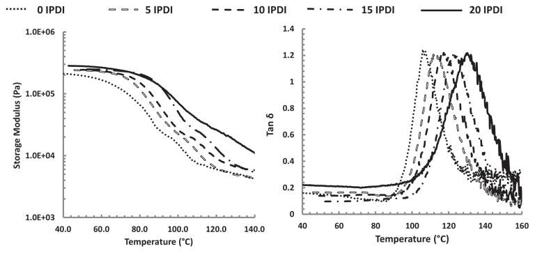
DMA of the foam compositions were conducted to determine changes in Tg as a function of storage modulus. Dynamic temperature sweeps, ranging from 25 to 150 °C, were conducted on the dry foam compositions using Triton Technology (TT) DMA (Mettler Toledo International, Inc., Columbus, OH). The frequency was set to 1 Hz, dynamic force to 0.1 N, and the ramp rate to 1 °C min−1. Cylindrical foam samples with a diameter of 6 mm and a height of 5 mm were used. Data points were collected every 20 s. Dynamic shear storage modulus (E′), dynamic shear loss modulus (E″), and tanδ (E″/E′) were recorded using the Titron Laboratory software (Mettler Toledo International, Inc., Columbus, OH). The peak of the tanδ curve and the inflection point of E′ indicated Tg for the dry foam samples.
2.3. Characterization of Hydrophobicity and Foam Actuation
2.3.1. Contact Angle
Hydrostatic contact angle measurements on neat polymer samples were done using KSV CAM-2008 Contact Angle Analyzer (KSV Instruments, Ltd., Helsinki, Finland). A 5 μL drop of DI water was placed on the sample surface. The drop was allowed to reach equilibrium for 60 s and the contact angle was measured using an Attension Tensometer and the Attension Theta software package (Biolin Scientific, Stockholm, Sweden). Contact angles were collected (n = 3) and the average was presented as the water contact angle for each neat polymer composition.
2.3.2. Phase Transition Rates in Water
Foam samples (3–8 mg) were submerged in RO water at 50 °C for 5 min to allow full plasticization. After the samples were removed from water, they were pressed dry with Kim Wipes (Kimberly-Clark Professionals, Roswell, GA), weighed, and placed in an aluminum pan sealed with an aluminum lid that was vented. Q-200 DSC was used to cool the samples to −40 °C, hold them isothermal for 2 min, and heat them to 80 °C at 10 °C min−1. TA instruments software was used to generate the thermogram and acquire the Tg, after water plasticization, using the average inflection point of the thermal transition of multiple measurements (n = 5).
2.3.3. Immersion DMA
Cylindrical foam samples with a diameter of 6 mm and a height of 5 mm were used in this procedure. The samples were crimped using the Carver Press to a height of 0.8 mm. TT DMA was used to collect the kinetic thermogram of various foam compositions at 37 and 50 °C. For each temperature, the samples were submerged in a PBS bath to mimic physiological osmolarity (pH 7), and changes in storage modulus (E′) were recorded using the TT DMA software. The frequency was set to 1.0 Hz, dynamic force to 0.1 N, and each run was carried out for 20 min. This test was conducted in triplicate per foam composition. The inflection point between E′onset and E′end corresponded to the actuation time for the sample.
2.3.4. Volume Recovery and Expansion
Cylindrical foam samples with a diameter of 6 mm and a height of 1 cm were cut. A 203.20 μm diameter nickel–titanium (Nitinol) wire (NDC, Fremont, CA) was inserted through the center of the sample along its length to serve as a stabilizer. The foam samples were radially compressed to their smallest possible diameter using ST 150–42 stent crimper (Machine Solutions, Flagstaff, AZ) by heating the material to 100 °C, holding it isothermal for 15 min, and programming the foams to the crimped morphology. Initial foam diameter was measured and recorded for each sample using Image J software (NIH, Bethesda, MD). The foams were placed in a water bath at 50 °C, removed after 20 min, and allowed to cool to room temperature. The final diameter of the samples was measured and recorded using Image J software. Volume expansion was calculated using Equation ( 1) and volume recovery was calculated using Equation 2.
| (1) |
| (2) |
3. Results and Discussion
3.1. Chemical and Mechanical Characterization
3.1.1. Density and Cell Structure
The measured foam densities are provided in Table 3. Multiple foam batches maintained ultralow densities, which were consistently ca. 12.5 mg cm−3. With batch-to-batch standard deviations ranging from 0.1 to 0.3 mg cm−3, our method allows for reproducible synthesis of uniform-celled SMP foams.
Table 3.
Summary of key physical properties of various foam compositions.
| Composition | Density [g cm−3] | Dry Tg [°C] | T′onset [°C] | T′1/2 [°C] | tanδmax [°C] |
|---|---|---|---|---|---|
| 0% IPDI | 0.0122 ± 0.0002 | 62 ± 1 | 55 ± 2 | 70 ± 2 | 105 ± 2 |
| 5% IPDI | 0.0119 ± 0.0002 | 64 ± 0.5 | 61 ± 1 | 78 ± 2 | 111 ± 1 |
| 10% IPDI | 0.0129 ± 0.0005 | 65 ± 0.5 | 65 ± 2 | 81 ± 3 | 118 ± 2 |
| 15% IPDI | 0.0132 ± 0.0001 | 67 ± 0.2 | 71 ± 1 | 88 ± 2 | 125 ± 2 |
| 20% IPDI | 0.0122 ± 0.0001 | 71 ± 2 | 76 ± 0.5 | 92 ± 2 | 131 ± 1 |
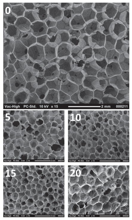
Analysis of the foam morphology with SEM revealed homogenous cells throughout different compositions, as depicted by Figure 2. It was evident that each foam composition consists of both open- and closed-cell pores and mixed open- and closed-cell pores. This would effectively provide initial reticulation of the foam and aid the removal of surfactants and catalysts during the cleaning process. Furthermore, the uniform cross-linked foam network suggests good shape memory behavior as explained by Singhal and co-workers. [6,7]
Figure 2.
SEM images of various foam compositions at 15× magnification. Images 0, 5, 10, 15, and 20 represent 0% IPDI, 5% IPDI, 10% IPDI, 15% IPDI, and 20% IPDI, respectively.
3.1.2. FTIR
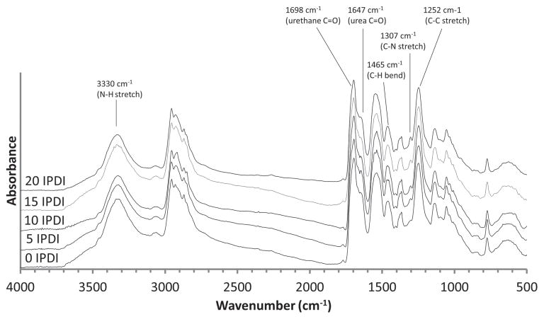
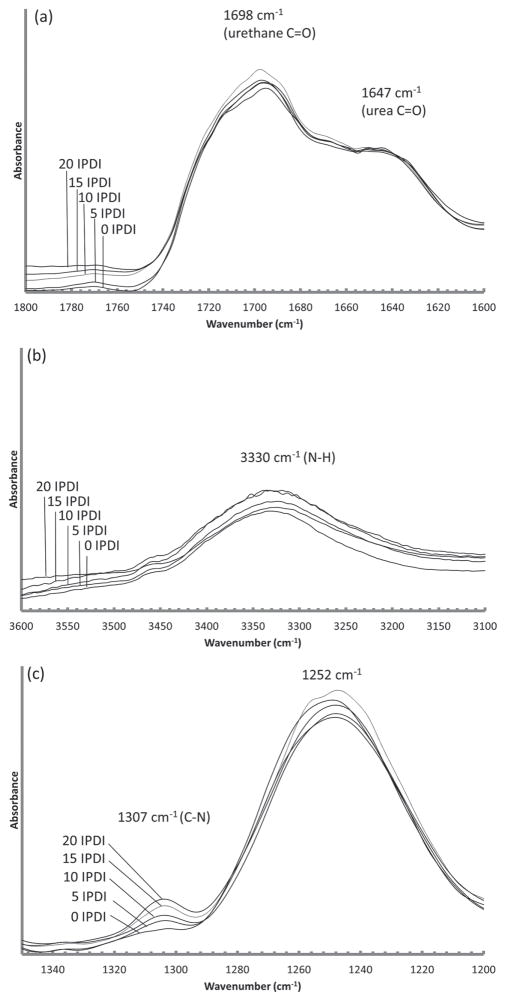
Selected FTIR spectral regions for the various foam compositions are presented in Figure 3. The hydrogen-bonded urethane C=O stretch (1698 cm−1) confirms a polyurethane system (Figure 4a). [30,31] A small amount of hydrogen-bonded urea can be observed on the urethane C=O shoulder (1647 cm−1) due to the reaction of isocyanates with water during the foaming step (Figure 4a). [30] The amine, a broad stretch (centered at 3330 cm−1), represents a combination of secondary and tertiary amine and is readily observed in all systems (Figure 4b). [31] The C–H peaks around 1465 cm−1 indicate a strong presence of methyl groups contributed from TMHDI and IPDI in each foam composition (Figure 3). [7] Lastly, the C–N peak (1307 cm−1) is indicative of both IPDI and TMHDI incorporation into the matrix (Figure 4c). The C–N stretch (normally 1020–1250 cm−1) is shifted to higher wave-numbers near-by methyl constituencies contributing to higher energy requirements for excitation. There is an initial C–N shoulder observed for 0 IPDI, however, an increase in the peak intensity with additional IPDI incorporation implies slightly higher reaction efficiency than TMHDI in these formulations.
Figure 3.
FTIR spectra of the IPDI-TMHDI SMP foam series.
Figure 4.
FTIR absorbance spectra for a) hydrogen-bonded urethane and urea. b) Secondary and tertiary amines in SMP systems and c) C-N groups contributed from IPDI and TMHDI.
3.1.3. DSC
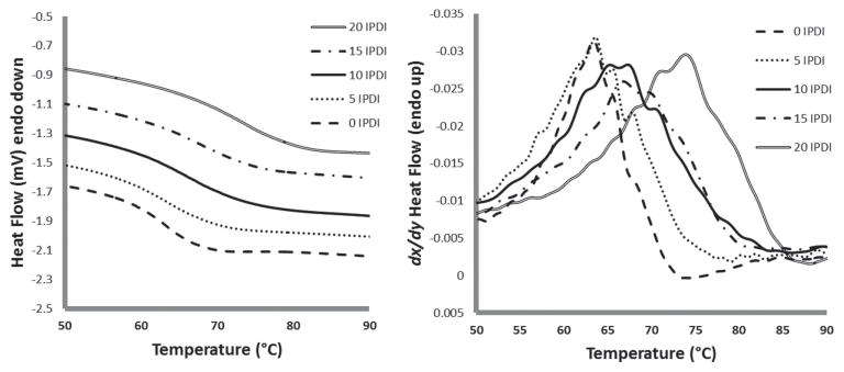
Thermal analysis of the foams shows an increase in Tg with higher IPDI content (Table 3 and Figure 5). The shift in Tg is significant from 62 °C for the 100% TMHDI control to 71 °C for 20% IPDI, which has the highest concentration of IPDI in the series. The increase in Tg is due to the increase in foam stiffness provided by the ring moiety of IPDI. Figure 5 shows the shift in Tg with increasing IPDI content. This indicates that the matrix is more constrained with additional IPDI content, delaying thermal actuation temperatures (e.g., Tg), which is reasonable given the sterics of the IPDI ring in comparison to semilinear TMHDI. [32,33]
Figure 5.
DSC thermogram of the IPDI-TMHDI SMP foam series (primary axis) and heat flow derivative (secondary axis). Glass-transition temperature increases with increasing IPDI content.
3.1.4. DMA
Thermal analysis of the foams using DMA provided relationships between glass transition temperatures as IPDI content that are comparable to the DSC findings (Figure 6). Maximum softening rate temperatures (E′1/2) increased from 70 to 91 °C when transitioning from 0% to 20% IPDI. A transition from 105 to 130 °C for tanδmax was similarly observed with increased IPDI content (Table 3).
Figure 6.
Storage modulus (E′) and tanδ curves of the IPDI-TMHDI SMP foam series.
3.2. Characterization of Hydrophobicity and Foam Actuation
3.2.1. Contact Angle
Hydrostatic contact angles of the neat/nonporous polymer networks (Table 4) make evident that hydrophobicity (e.g., contact angle) is increasing with IPDI content. [34,35] Ultimately, the increase in contact angle (76° → 98°) with increased IPDI content indicates that the constrained, ring-containing moiety is significantly reducing the rate of water intercalation into the matrix and is an appropriate formulation component for tuning kinetics from solvent plasticization.
Table 4.
Summary of the foam properties related to actuation and working time.
| Composition | Dry Tga) [°C] | Wet Tg [°C] | Contact angle [°] | Volume recovery (x) | Volume expansion [%] | Working time at 37 °C b) [s] | Working time at 50 °C b) [s] |
|---|---|---|---|---|---|---|---|
| 0% IPDI | 62 ± 1 | 30 ± 1 | 76 ± 1 | 66 ± 8 | 148 ± 25 | 246 ± 33 | 54 ± 20 |
| 5% IPDI | 64 ± 0.5 | 33 ± 1 | 80 ± 1 | 57 ± 9 | 105 ± 9 | 333 ± 59 | 58 ± 9 |
| 10% IPDI | 65 ± 0.5 | 39 ± 3 | 84 ± 0.3 | 46 ± 8 | 88 ± 7 | >1200 | 81 ± 25 |
| 15% IPDI | 67 ± 0.2 | 53 ± 1 | 94 ± 1 | 46 ± 8 | 87 ± 5 | >1200 | 135 ± 23 |
| 20% IPDI | 71 ± 2 | 57 ± 0.5 | 98 ± 0.3 | 39 ± 8 | 83 ± 23 | >1200 | 135 ± 22 |
Tg dry reproduced from Table 3 for comparative purposes;
Working time defined as the time when the foam is exposed to an aqueous environment the catheter to the time when it is no longer retractable.
3.2.2. Phase Transition Rates in Water
For all of the SM’P formulations investigated, actuation can be induced by conventional thermal means (heat to Tg) or at lower temperatures with moisture-based plasticization. [7] Wet Tgs (from DSC) are provided in Table 4. For our entire array of foam compositions, there is a significant decrease in Tg after exposure to RO water when compared with dry foams. For example, there is a drop in Tg from 62 to 30 °C for the control (0% IPDI) upon introduction to water. For the remaining foams containing IPDI, there is a trend of higher transition temperature as we increase the IPDI content, even after exposure to water. This displays that the hydrophobicity and increased steric restrictions to movement introduced with IPDI incorporation can successfully allow for application-tailored glass transition temperatures in the range of 30–57 °C.
3.2.3. Immersion DMA
The working times derived from immersion DMA are shown in Table 4. The range of working times is 5 min for 0 IPDI, to no actuation in 37 °C PBS as IPDI concentrations are increased in the SMP foams (Figure 7). The decay in storage modulus was the indicator for actuation and for foam compositions above 5 IPDI, there was no decay in E′ during the 20 min kinetic run. This displays that at body temperature the higher 10 IPDI, 15 IPDI, and 20 IPDI foams will yield a working time greater than 20 min, though analysis at 50 °C indicates rapid actuation for all systems. Overall, the foams with higher IPDI content yielded a longer working time due to delayed actuation, though all systems are readily actuated in 50 °C water.
Figure 7.
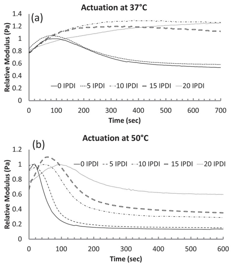
Actuation of the SMP foam depicted by a decay in E′ in a) 37 °C and b) 50 °C PBS bath.
3.2.4. Volume Recovery and Expansion
The volume recovery of the foams can be readily observed in Figure 8. The control samples of 0 IPDI experienced ca. 66-fold volume recovery upon submersion in 70 °C RO water and higher IPDI compositions had volume recoveries below 50-fold (Table 4). These results indicate that a degree of constraint exists with increased IPDI content, both in terms of ultimate compression above Tg and recovery, which is reasonable given the mechanical and hydrophobicity trends in our systems. Despite a decreased volume recovery, all foam samples expanded to 80%+ in water (Table 4). In terms of application, we envision these systems as application-tunable materials where one may select from 5% to 15% content based on working time needs. Also a fortuitous finding in terms of application, all systems have actuation times ca. 1–2 min at 50 °C; this means that, should a surgical application require rapid foam expansion after placement/working time considerations are met, a rapid warm water actuation is possible.
Figure 8.
Volume expansion images for 0 IPDI, 10 IPDI, and 20 IPDI, respectively. As IPDI content increases in the foams, the shape recovery to full expansion decreases.
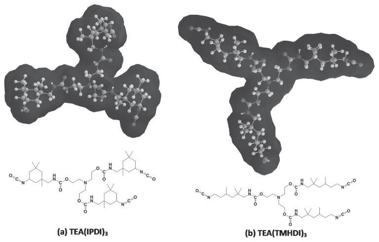
An ad hoc assessment of surface availability was made using ChemDraw 13 for MM2 energy-minimized 3D renderings of the space filling models of various monomer couplings. Given the differences observed in thermal, mechanical, kinetic, and recovery response of these systems despite the similar empirical formulas of the system precursors, it is reasonable to have an ad hoc discussion of TMHDI and IPDI availability to when linked to TEA. Energy-minimized structures of TEA bound to TMHDI versus IPDI revealed significantly different solvent availability (Figure 9). Figure 9a displays a urethane structure composed of TEA and IPDI that has a lower availability to the ternary amine and the urethane linkages (e.g., the nonaliphatic, polar regions of the structure) than that of the TEA and TMHDI structure (Figure 9b). In brief, the constrained nature of the IPDI cyclohexyl moiety does not allow the free rotation of the bonds along a methylene backbone (as in TMHDI) and enforces limited expansion, even with some water association at the polar regions.
Figure 9.
Molecular geometries and solvent interaction for: a) TEA(IPDI)3 and b) TEA(TMHDI)3. The chains are more tightly packed due to restricted movement from IPDI in (a) while appear to have free rotation due to the linear backbone of TMHDI in (b).
Overall, incorporation of IPDI into our shape-memory foams increased the actuation time and therefore provided an elongated working time for the foams (Table 4). The glass transition temperature of the foams also increased with greater IPDI content due to the added stiffness from the IPDI aliphatic C-C ring (Figure 1 and 5 ). As the material became stiffer, it was more difficult for the polymer chains to achieve mobility and become rubbery. Therefore, higher temperatures were required to allow the material to transition from the glassy to the rubbery state. Using foams with higher IPDI content, such as 10 IPDI, can ensure that the crimped foam will not expand immediately at physiological temperature while being delivered through the catheter. However, passive actuation will eventually occur once the foam has been deployed in the aneurysm (Figure 7). One trade-off to consider is the percent volume recovery for the foam. Clearly, 10 IPDI only yields 46% volume recovery at 70 °C, which indicates that the foam will passively actuate even slower at physiological temperature as shown in Table 4. However, upon reaching full actuation, the volume expansion of 88% will ensure full occlusion of the aneurysm space (Figure 8). Additionally, the computational solvent interaction images (Figure 9) suggest poor solvent interaction for urethanes synthesized with IPDI compared with TMHDI, which supports decreased volume recovery of the foams in water. Nevertheless, the higher working time will be beneficial during foam delivery and the shape-filling properties of the foam will be advantageous to promote occlusion and block blood flow to the aneurysm.
4. Conclusion
We have successfully synthesized shape-memory polymer foams with slower actuation times by incorporating isophorone diisocyanate (IPDI) into the foam matrix. The foams containing 10% IPDI remain crimped during the 20-min test interval at physiological temperature, thus providing sufficient working time for the foam to be delivered to the aneurysm site without premature actuation in the catheter. Additionally, these systems showed rapid actuation (1–2 min) under warmed water conditions that may serve as a potential for rapid actuation as surgical conditions require. Higher IPDI content for the foams also resulted in an increased glass transition temperature and foam hydrophobicity, which helps elongate the working time and delay water plasticization of the material. One drawback of delayed actuation was the decrease in volume recovery of the foam; however, all systems displayed total volume expansion to 80%+ of the precrimped state. We discuss these effects in terms of the molecular effects of IPDI incorporation, such as poor solvent interaction, decreased subunit mobility, and the resultant mechanical, thermal, and hydrophilic responses.
Acknowledgments
This work was supported by the National Institutes of Health/National Institute of Biomedical Imaging and Bioengineering grant R01EB000462 and the Texas A&M University Graduate Diversity Fellowship. The authors thank Marilyn Brooks, Rachael Muschalek, Jennifer Rodriguez, Anthony Boyle, Andrew Weems, and Landon Nash for their technical support on this research.
Contributor Information
Sayyeda M. Hasan, Department of Biomedical Engineering, 5045 Emerging Technologies Building, 3120 TAMU, College Station, TX-77843, USA
Dr. Jeffery E. Raymond, Department of Chemistry, 1031 Chemistry Complex, 3012 TAMU, College Station, TX-77842, USA
Dr. Thomas S. Wilson, Physical and Life Sciences Directorate, Lawrence Livermore National Laboratory, 7000 East Avenue, Livermore, CA-94550, USA
Dr. Brandis K. Keller, Department of Biomedical Engineering, 5045 Emerging Technologies Building, 3120 TAMU, College Station, TX-77843, USA
Dr. Duncan J. Maitland, Department of Biomedical Engineering, 5045 Emerging Technologies Building, 3120 TAMU, College Station, TX-77843, USA
References
- 1.Meng H, Li G. Polymer. 2013;54:2199. [Google Scholar]
- 2.Maitland DJ, Metzger MF, Schumann D, Lee A, Wilson TS. Lasers Surg Med. 2002;30:1. doi: 10.1002/lsm.10007. [DOI] [PubMed] [Google Scholar]
- 3.Cullum BM, Wilson TS, Small W, IV, Benett WJ, Bearinger JP, Maitland DJ, Carter JC. Proc SPIE. 2005;6007:60070R. [Google Scholar]
- 4.Small W, IV, Singhal P, Wilson TS, Maitland DJ. J Mater Chem. 2010;20:3356. doi: 10.1039/B923717H. [DOI] [PMC free article] [PubMed] [Google Scholar]
- 5.Wilson TS, Bearinger JP, Herberg JL, Marion JE, Wright WJ, Evans CL, Maitland DJ. J Appl Polym Sci. 2007;106:540. [Google Scholar]
- 6.Singhal P, Rodriguez JN, Small W, Eagleston S, Van de Water J, Maitland DJ, Wilson TS. J Polym Sci, Part B: Polym Phys. 2012;50:724. doi: 10.1002/polb.23056. [DOI] [PMC free article] [PubMed] [Google Scholar]
- 7.Singhal P, Boyle A, Brooks ML, Infanger S, Letts S, Small W, Maitland DJ, Wilson TS. Macromol Chem Phys. 2013;214:1204. doi: 10.1002/macp.201200342. [DOI] [PMC free article] [PubMed] [Google Scholar]
- 8.Singhal P, Small W, Cosgriff-Hernandez E, Maitland DJ, Wilson TS. Acta Biomater. 2014;10:67. doi: 10.1016/j.actbio.2013.09.027. [DOI] [PMC free article] [PubMed] [Google Scholar]
- 9.Rodriguez JN, Yu YJ, Miller MW, Wilson TS, Hartman J, Clubb FJ, Gentry B, Maitland DJ. Ann Biomed Eng. 2012;40:883. doi: 10.1007/s10439-011-0468-1. [DOI] [PMC free article] [PubMed] [Google Scholar]
- 10.Xie T. Polymer. 2011;52:4985. [Google Scholar]
- 11.Leng J, Lan X, Liu Y, Du S. Prog Mater Sci. 2011;56:1077. [Google Scholar]
- 12.Chae Jung Y, Hwa So H, Whan Cho J. J Macromol Sci, Phys. 2006;45:453. [Google Scholar]
- 13.Hearon K, Singhal P, Horn J, Small W, IV, Olsovsky C, Maitland KC, Wilson TS, Maitland DJ. Polym Rev. 2013;53:41. doi: 10.1080/15583724.2012.751399. [DOI] [PMC free article] [PubMed] [Google Scholar]
- 14.Cerebral aneurysm. American Association of Neurological Surgeons; [accessed: July 2014]. www.Aans.Org. [Google Scholar]
- 15.What you should know about cerebral aneurysms. American Heart Association; [accessed: July 2014]. www.Strokeassociation.Org. [Google Scholar]
- 16.Warlow CP. Lancet. 1998;352:S1. doi: 10.1016/s0140-6736(98)90086-1. [DOI] [PubMed] [Google Scholar]
- 17.Juvela S, Poussa K, Porras M. Stroke. 2001;32:485. doi: 10.1161/01.str.32.2.485. [DOI] [PubMed] [Google Scholar]
- 18.Hayakawa M, Murayama Y, Duckwiler GR, Gobin YP, Guglielmi G, Vinuela F. J Neurosurg. 2000;93:561. doi: 10.3171/jns.2000.93.4.0561. [DOI] [PubMed] [Google Scholar]
- 19.Sluzewski M, Bosch JA, Rooij WJV, Nijssen PCG, Wijnalda D. J Neurosurg. 2001;94:238. doi: 10.3171/jns.2001.94.2.0238. [DOI] [PubMed] [Google Scholar]
- 20.Ullmann F. Ullmann’s Encyclopedia of Industrial Chemistry. John Wiley and Sons, Inc; Hoboken, NJ, USA: pp. 1999–2014. [Google Scholar]
- 21.Kim JH, Kang TJ, Yu WR. J Biomech. 2010;43:632. doi: 10.1016/j.jbiomech.2009.10.032. [DOI] [PubMed] [Google Scholar]
- 22.Xue L, Dai S, Li Z. Biomaterials. 2010;31:8132. doi: 10.1016/j.biomaterials.2010.07.043. [DOI] [PubMed] [Google Scholar]
- 23.Laschke MW, Strohe A, Scheuer C, Eglin D, Verrier S, Alini M, Pohlemann T, Menger MD. Acta Biomater. 2009;5:1991. doi: 10.1016/j.actbio.2009.02.006. [DOI] [PubMed] [Google Scholar]
- 24.Hong Y, Ye SH, Pelinescu AL, Wagner WR. Biomacromolecules. 2012;13:3686. doi: 10.1021/bm301158j. [DOI] [PMC free article] [PubMed] [Google Scholar]
- 25.Page JM, Prieto EM, Dumas JE, Zienkiewicz KJ, Wenke JC, Brown-Baer P, Guelcher SA. Acta Biomater. 2012;8:4405. doi: 10.1016/j.actbio.2012.07.037. [DOI] [PubMed] [Google Scholar]
- 26.Huang WM, Yang B, Zhao Y, Ding Z. J Mater Chem. 2010;20:3367. [Google Scholar]
- 27.Frigione M, Aiello MA, Naddeo C. Constr Build Mater. 2006;20:957. [Google Scholar]
- 28.Yu YJ, Hearon K, Wilson TS, Maitland DJ. Smart Mater Struct. 2011;20:1. doi: 10.1088/0964-1726/20/8/085010. [DOI] [PMC free article] [PubMed] [Google Scholar]
- 29.Hwang W, Singhal P, Miller MW, Maitland DJ. J Med Dev. 2013;7:020932. [Google Scholar]
- 30.Zhang S, Ren Z, He S, Zhu Y, Zhu C. Spectrochim Acta Part A. 2007;66:188. doi: 10.1016/j.saa.2006.02.041. [DOI] [PubMed] [Google Scholar]
- 31.Zhang Y, Maxted J, Barber A, Lowe C, Smith R. Polym Degrad Stab. 2013;98:527. [Google Scholar]
- 32.Crompton TR. Thermal Methods of Polymer Analysis. Smithers Rapra Technology; Akron, OH, USA: 2013. [Google Scholar]
- 33.Young RJ, Lovell PA. Introduction to Polymers. CRC Press, Taylor and Francis Group LLC; Boca Raton, FL, USA: 2011. [Google Scholar]
- 34.Bracco G, Holst B, editors. Surface Science Techniques, Springer Series in Surface Science. Vol. 51. Springer; New York: 2013. [Google Scholar]
- 35.Kwok DY, Neumann AW. Colloids Surf, A. 2000;161:31. [Google Scholar]


