

Abstract
Deficiency of the eye-stabilizing vestibulo-ocular reflex (VOR) is a defining feature in multiple diseases of the vestibular labyrinth, which comprises the inner ear’s sensors of head rotation, translation and orientation. Diagnosis of these disorders is facilitated by observation and measurement of eye movements during and after head motion. The video head impulse test has recently garnered interest as a clinical diagnostic assessment of vestibular dysfunction. In typical practice, it involves use of video-oculography goggles to measure eye movements while a clinician examiner grasps the subject’s head and manually rotates it left or right at sufficient acceleration to cover ~20 deg over ~150 mS, reaching a peak velocity of >120 deg/S midway through the movement. Manual delivery of head impulses incurs significant trial-by-trial, inter-session and inter-operator variability, which lessens the test’s reliability, efficiency, safety and standardization across testing facilities. We describe application of a novel, compact and portable automated head impulse test (aHIT™) device that delivers highly repeatable head motion stimuli about axes parallel to those of the vestibular labyrinth’s six semicircular canals, with programmable Gaussian and sinusoidal motion profiles at amplitudes, velocities and accelerations sufficient to test VOR function over the spectral range for which the VOR dominates other vision-stabilizing reflexes. We tested the aHIT™ on human subjects and demonstrated its high reproducibility compared to manually delivered head impulses. This device has the potential to be a valuable clinical and research tool for diagnostic evaluation and investigation of the vestibular system.
Keywords: vestibular system, head impulse test, vestibulo-ocular reflex, automated head impulse test, aHIT
I. Introduction
A. Vestibular System
The vestibular system comprises several reflexes that together maintain stable posture, vision and perception of head and body orientation and movement relative to the world [1, 2]. The vestibular sensors comprise 5 neuroepithelial end organs in each of the inner ears. In each ear, three semicircular canals (SCCs)—commonly called the horizontal, anterior and posterior canals—are oriented orthogonally to one another and configured so that each senses one component of three-dimensional head angular velocity, while being insensitive to angular position, other components of angular velocity, translation, and changing in linear acceleration due to head reorientation with respect to the direction of gravity (Fig. 1). Conversely, the utricle and saccule sense linear accelerations, in approximately horizontal and parasagittal planes, respectively. In a person standing upright with the head pitched ~20° nose-down from level, the horizontal SCCs sense head rotation in the earth-horizontal plane. In that orientation, the anterior and posterior SCCs are oriented vertically and ~45° off the midsagittal plane. The left anterior and right posterior semicircular canals detect head rotation in the left-anterior/right-posterior (LARP) plane, and the right anterior and left posterior semicircular canals detect head rotation in the right-anterior/left-posterior (RALP) plane.
Fig. 1.
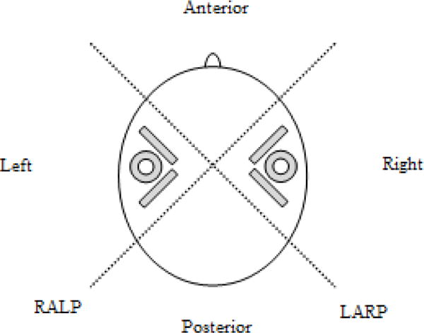
Orientation of semi-circular canals (in gray) with respect to the human head, as viewed from above. Dotted lines represent the LARP and RALP axes.
Activation of the semicircular canals elicits the angular vestibulo-ocular reflex (VOR), which normally drives eye rotation opposite and equal in velocity to head rotation, thereby ensuring that the image of a distant, Earth-fixed object remains stable on the retina despite head motion. This reflex fails in individuals disabled by loss of vestibular sensation, which can cause debilitating vertigo, oscillopsia and gait disturbances [3].
B. Head Impulse Testing
The head impulse test (HIT) was popularized by Halmagyi and Curthoys for clinical diagnosis of peripheral vestibular disease [4]. Since their initial publication in 1988, the HIT has gained popularity and become an integral part of the work-up of vestibular symptoms. A head impulse is described as a head rotation with low amplitudes of 5-20°, intermediate peak velocities of about 150°/s, and high peak accelerations of 1000-6000°/s2, in unpredictable timing and direction, in the planes of the semicircular canals [5]. These are traditionally done manually, with an examiner firmly grasping the patient’s head and delivering head-on-body impulses in the horizontal, RALP, and LARP planes. In a normal subject, a rapid “head impulse” head rotation activates the VOR and produce reflexive eye motion equal in amplitude and velocity to the head motion. In a person with deficient vestibular sensation in one ear, rapid head movements towards the hypofunctioning semicircular canal elicit a deficient VOR, so that the eye fails to maintain stable orientation with respect to the world. Compensatory refixation saccades are quick eye movements that bring the eye back on target. When such refixation movements occur after the head stops moving, they are readily visible to an examiner, who can then easily identify the specific hypofunctioning semicircular canal(s) without special equipment. However, when compensatory saccades occur during the head motion, they are difficult to detect without the aid of equipment able to sample and accurately measure eye angular position at a sufficiently high rate [6]. Detection of these “covert saccades” and measurement of subtle changes in VOR gain (eye velocity/head velocity) is more difficult when the head motion stimuli are highly variable in speed and acceleration. Head impulse rotation stimuli delivered manually are variable and inherently operator-dependent. In addition, head impulses in the RALP and LARP planes are often difficult to apply consistently without variation in rotation axis and motion profile [7].
C. Video head impulse test (vHIT)
Recently, video-oculography (VOG) has been used during head impulse testing, creating the video head impulse test (vHIT) [8]. VOG allows tracking of eye movement during head motion with a camera, and is a less invasive method of eye-tracking compared to scleral search coils [9]. VOG allows the detection of covert saccades, or saccades that occur during the head impulse, and are difficult for the unaided observer to detect [10]. Commonly used VOG systems include the ICS Impulse (GN Otometrics) and EyeSeeCam (Interacoustics) systems. These devices measure head velocity in conjunction with eye velocity to calculate VOR gain [11]. As such, the vHIT can isolate pathology to one of the six semicircular canals [12], and determine the VOR gain of each canal [13].
In determining VOR gain, it is important that the peak velocities of the head impulses are high enough to trigger the VOR. In the ICS Impulse system, for a motion to be detected as a head impulse, lateral head velocity must be greater than 120°/s, and the LARP/RALP head velocity must be greater than 100°/s. For the EyeSeeCam system, peak head velocity and acceleration must exceed 70°/s and 1000°/s2, respectively, for a movement to be detected as a head impulse. It can be difficult for a testing technician or other clinician examiner to consistently deliver head impulses that meet these motion constraints, particularly in the LARP and RALP planes. Consequently, test subjects sometimes must endure numerous head impulses to acquire sufficient data for calculation of VOR gain. When the examiner is relatively inexperienced, head motion stimuli may be either too slow (resulting in unreliable responses) or too large in amplitude (posing a risk of neck injury). Moreover, operator-dependence of the vHIT test as typically performed causes a lack of standardization across testing centers. These concerns have led to interest in finding a reliable method to automatically and consistently deliver head motion stimuli.
D. Motorized head impulse devices
Tabak and Collewijn developed an early motor-driven head impulse testing device in 1994 [14, 15]. In their set-up, the subject wore a helmet connected to a torque motor attached to the ceiling. That device delivered horizontal sinusoidal head movements up to a frequency of 20 Hz and step displacements (essentially “head impulses”) with amplitudes of 10-50°, peak velocities of 100-200°/s, and accelerations of 700-1300°/s2. However, it only delivered motion in the horizontal plane. Another motor-driven head impulse stimulator was reported by Aalto et al. in 2002 [16]. A DC motor and gear were attached to the backrest of a chair. The subject was seated in the chair, and wore a helmet attached to the gear with three rods. That system delivered impulses with peak velocities up to 100°/s at acceleration of 1000°/s2. Like the Tabak et al. device, the Aalto et al. stimulator only delivered movements in the horizontal plane. Both systems were bulky and not easily portable.
Impulses can also be delivered to the whole body, with the patient in a rotary chair [17]. As the chair is powered by a motor, it is capable of providing impulses at defined velocities and accelerations. Rotary chair systems also have the benefit of testing VOR function independent of contributions from the cervico-ocular reflex (COR); however, rotary chair systems are large and expensive to purchase, install and maintain. Furthermore, while some rotary chair systems allow movement about axes other than the Earth-vertical axis [18, 19], most only allow rotation in the horizontal plane. In addition, most rotary chairs can only rotate up to a peak velocity of 50-90°/s [20] and accelerations too small to generate the excitation-inhibition asymmetry essential to performance of the head impulse test.
E. Automated head impulse test (aHIT)
Here, we describe application of an automated head impulse testing device, the Labyrinth Devices aHIT™, which delivers repeatable, standardized, head impulse stimuli [21]. It consists of a servo motor connected to a curved stainless steel track guided by six stainless steel bearings to produce rotation of a mouthpiece (Fig. 2). The subject bites onto the mouthpiece covered with dental putty, which serves to protect the subject’s teeth. The motor displaces the track, and these movements are transmitted to the subject via the mouthpiece. The servo motor can be programmed to administer a variety of head impulse motion profiles, including Gaussian, sinusoidal, and trapezoidal velocity waveforms, at a range of amplitudes, velocities, and accelerations. The orientation of the track and mouthpiece can be adjusted to allow delivery of head impulses in the LARP and RALP planes, in addition to the horizontal plane. The device measures 32 × 28 × 27cm, weighs 5kg - an order of magnitude smaller and lighter than most rotary chair systems - so it occupies only a fraction of a clinic exam room and can easily be disassembled and moved to free an exam room space for other equipment.
Fig. 2.
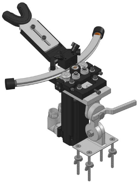
aHIT™ device, consisting of a servo motor, which is connected to a curved track guided by bearings; the curved track is attached to a mouth piece
II. Materials and methods
This study was approved by the Johns Hopkins University Institutional Review Board. A healthy subject with no history or symptom of vestibular dysfunction was recruited for validation of the aHIT™ device.
A. aHIT™ motion profile testing
A wireless sensor with gyrometer (Shimmer™ 3 [22]) at a sampling rate of 204.8Hz was used to measure angular velocity of the subject’s head. It was attached to a headband and placed around the subject’s forehead.
A dental impression of each subject was made using dental putty and placed on the bite block the aHIT device. The subject was seated upright, and the height of the chair was adjusted so that the bite block was at a comfortable level for the subject. The bite block was also adjusted to ensure that the axis of rotation was centered about the vertical axis of the subject’s head. During head motions, the subject was asked to bite down on the bite block firmly to ensure transfer of forces from the motor.
The aHIT™ device was used to deliver the following motion profiles:
Sinusoid, frequency 0.5Hz, peak angular velocity 35°/s
Sinusoid, frequency 1Hz, peak angular velocity 70°/s
Sinusoid, frequency 2Hz, peak angular velocity 140°/s
Gaussian, peak angular velocity 150°/s, peak acceleration 3000°/s2.
The aHIT™ was first configured to deliver these motions in the horizontal plane. For each motion profile, 10 cycles were delivered in the horizontal plane, with each cycle consisting of a motion to the left, then to the right. The track and bite block were then oriented to deliver these motions in the LARP and RALP planes in similar fashion.
B. Manual head impulse testing
For comparison to aHIT™ data, an experienced clinician delivered ten head impulses in the maximally excitatory direction for each SCC. Motion of the subject’s head was similarly recorded with the Shimmer™ 3.
III. Results
Fig. 3 shows one subject’s head angular velocity during sinusoids with frequencies of 0.5, 1 and 2 Hz at peak velocities of 35°/s, 70°/s, and 140°/s respectively are delivered by the aHIT™ in the horizontal, LARP, and RALP planes. These waveforms demonstrate that when the sinusoidal motion in applied in the horizontal, LARP, or RALP plane, the predominant motion of the head is in the intended plane, with little off-axis motion. These waveforms also contain high frequency noise in the velocity signal.
Fig. 3.
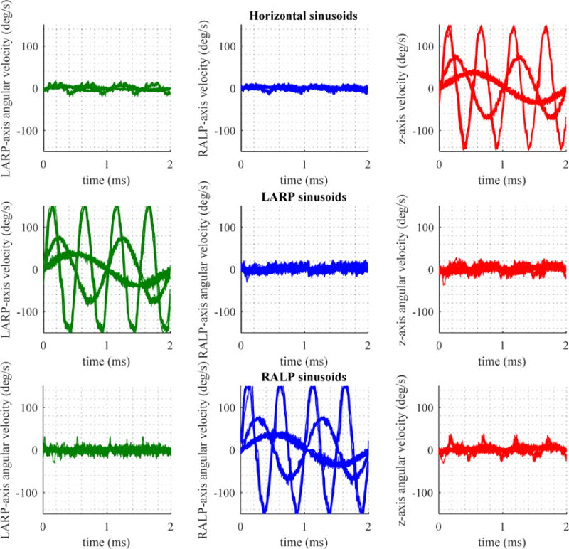
Head angular velocity on aHIT device delivering sinusoids in the horizontal (top), LARP (middle) and RALP (bottom) planes, at frequency of 0.5Hz with peak velocity 35 °/s, frequency of 1Hz with peak velocity of 70°/s, and frequency of 2Hz with peak velocity of 140°/s. Green traces are motions in the LARP axis, blue traces are motions in the RALP axis, and red traces are velocities in the z axis, or horizontal plane.
Fig. 4a shows velocity profiles of manual head impulses delivered by an experienced clinician in the horizontal, RALP and LARP planes. They approximate a Gaussian waveform. There is considerable variation in the peak velocity (standard deviation ranging from 17.8 to 59.0, Table 1) of these head impulses. Furthermore, there is considerable off-axis motion for head impulses in all planes.
Fig. 4.
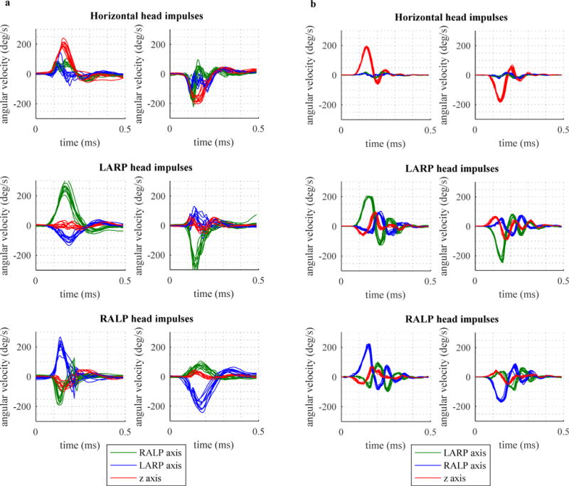
4a: Ten head impulses by clinician in each plot, 4b: Ten head impulses with aHIT device in each plot; in the horizontal (top), LARP (middle) and RALP (bottom) planes.
TABLE I.
Means and standard deviations (S.D.) of peak velocities in manual versus aHIT impulses
| Canal plane | Manual impulses | aHIT™ impulses | ||
|---|---|---|---|---|
| Mean | S.D. | Mean | S.D. | |
| Left horizontal | 202.4 | 18.7 | 188.6 | 4.9 |
| Right horizontal | −177.3 | 17.8 | −176.0 | 6.0 |
| Right posterior | 254.7 | 30.2 | 201.7 | 3.0 |
| Left anterior | −279.4 | 59.0 | −233.1 | 10.9 |
| Right anterior | 214.7 | 35.7 | 215.6 | 7.6 |
| Left posterior | −196.1 | 28.1 | −164.1 | 4.6 |
Fig. 4b shows velocity profiles when the aHIT™ device is programmed to deliver impulses with a motion profile of a Gaussian waveform with a peak velocity of 150°/s and peak acceleration of 3000°/s2. The resultant velocity profiles resemble sinusoids with exponential decay. There is decreased variation in the peak velocity (standard deviation ranging from 3.0 to 10.9, Table 1). Off-axis motion in the horizontal plane is minimal, while off-axis motion in the LARP and RALP planes reach velocities similar to those of manual head impulses.
IV. Discussion
Video head impulse testing has gained in popularity since its introduction, and is now a first-line tool used in the diagnosis of many vestibular disorders. This test typically depends on a clinician consistently providing impulsive head movements with motion profiles in the plane of the semicircular canals. These motions are difficult to perfect reproducibly without training, practice and experience.
The aHIT™ fills the need for a method to reliably deliver head impulses of specific motion profiles in the axes of the semicircular canals. When sinusoidal motion profiles are delivered in the horizontal, LARP or RALP plane, there is limited off-axis motion, demonstrating that the aHIT™ can consistently provide motions that are largely confined to the intended plane. However, when Gaussian motion profiles are applied with the aHIT™, there is some off-axis motion, particularly when the impulse is applied in the LARP and RALP planes. This may be because in those configurations, the curved track is oriented off the main axis of the device. This, coupled with the increased peak acceleration in a Gaussian impulse (~3000 °/s2) when compared to a 2Hz sinusoid (~900°/s2), may create oscillatory movements of the bite block about an axis tangential to the curved track. Nevertheless, the velocities of these off-axis motions are similar in magnitude to the velocities of the off-axis motions in a manual head impulse.
Motion waveforms contain high frequency noise which is particularly apparent for sinusoidal motions. This mechanical noise is most likely due to irregularities on the surfaces of the curved track that mate with bearings. Urethane or similar bearing coatings may diminish this high frequency noise.
Despite these limitations, the aHIT™ safely and reproducibly delivers impulses with velocities up to 200°/s and accelerations up to 3000 °/s2 in a largely operator-independent fashion.
V. Conclusion
We have demonstrated the ability to use an automated system to reproducibly create head motion profiles in the three orthogonal planes of the human semicircular canals. These motions are similar in profile to manually applied head impulses but are noted to have decreased variability. There is great clinical and research potential for a device capable of repeatedly delivering clinically relevant head impulses. Further device development will focus on decreasing high frequency noise in the sinusoidal motion profiles and diminishing off-axis motion in the LARP and RALP planes. Future studies will look at using this technology in the clinical setting and in vestibular research.
Contributor Information
Grace X. Tan, Department of Otolaryngology, Head and Neck Surgery, Johns Hopkins University School of Medicine, Baltimore, MD, USA
Desi P. Schoo, Department of Otolaryngology, Head and Neck Surgery, Johns Hopkins University School of Medicine, Baltimore, MD, USA
Charles C. Della Santina, Department of Otolaryngology, Head and Neck Surgery, Johns Hopkins University School of Medicine, Baltimore, MD, USA
Mehdi A. Rahman, Labyrinth Devices, Baltimore, MD, USA
Nicolas S. Valentin Contreras, Labyrinth Devices, Baltimore, MD, USA
Chen-Hsin Sun, Department of Ophthalmology, National University Hospital, Singapore.
Bryce Chiang, Emory University School of Medicine, Atlanta, GA, USA.
References
- 1.Lysakowski A. Anatomy of the Vestibular System. In: Flint P, Cummings C, editors. Cummings Otolaryngology - Head and Neck Surgery. 5th. Philadelphia, PA: Mosby/Elsevier; 2010. pp. 1850–1865. [Google Scholar]
- 2.Carey JP, Della Santina CC. Principles of Applied Vestibular Physiology. In: Flint P, Cummings C, editors. Cummings Otolaryngology - Head and Neck Surgery. 5th. Philadelphia, PA: Mosby/Elsevier; 2010. pp. 2276–2304. [Google Scholar]
- 3.Crane BT, Schessel DA, Nedzelski J, Minor LB. Peripheral Vestibular Disorders. In: Flint P, Cummings C, editors. Cummings Otolaryngology - Head and Neck Surgery. 5th. Philadelphia, PA: Mosby/Elsevier; 2010. pp. 2328–2345. [Google Scholar]
- 4.Halmagyi GM, Curthoys IS. A clinical sign of canal Paresis. Archives of Neurology. 1988 Jul;45(7):737–739. doi: 10.1001/archneur.1988.00520310043015. [DOI] [PubMed] [Google Scholar]
- 5.Halmagyi GM, Aw ST, Cremer PD, Curthoys IS, Todd MJ. Impulsive testing of individual semicircular canal function. Annals of the New York Academy of Sciences. 2006 Jan;942(1):192–200. doi: 10.1111/j.1749-6632.2001.tb03745.x. [DOI] [PubMed] [Google Scholar]
- 6.Cremer P. Semicircular canal plane head impulses detect absent function of individual semicircular canals. Brain. 1998 Apr;121(4):699–716. doi: 10.1093/brain/121.4.699. [DOI] [PubMed] [Google Scholar]
- 7.MacDougall HG, McGarvie LA, Halmagyi GM, Curthoys IS, Weber KP. Application of the video head impulse test to detect vertical semicircular canal dysfunction. Otology & Neurotology. 2013 Aug;34(6):974–979. doi: 10.1097/MAO.0b013e31828d676d. [DOI] [PubMed] [Google Scholar]
- 8.Bartl K, Lehnen N, Kohlbecher S, Schneider E. Head impulse testing using Video-oculography. Annals of the New York Academy of Sciences. 2009 May;1164(1):331–333. doi: 10.1111/j.1749-6632.2009.03850.x. [DOI] [PubMed] [Google Scholar]
- 9.Robinson DA. A method of measuring eye Movemnent using a Scieral search coil in a magnetic field. IEEE Transactions on Biomedical Electronics. 1963 Oct;10(4):137–145. doi: 10.1109/tbmel.1963.4322822. [DOI] [PubMed] [Google Scholar]
- 10.Weber KP, MacDougall HG, Halmagyi GM, Curthoys IS. Impulsive testing of semicircular-canal function using Video-oculography. Annals of the New York Academy of Sciences. 2009 May;1164(1):486–491. doi: 10.1111/j.1749-6632.2008.03730.x. [DOI] [PubMed] [Google Scholar]
- 11.MacDougall HG, Weber KP, McGarvie LA, Halmagyi GM, Curthoys IS. The video head impulse test: Diagnostic accuracy in peripheral vestibulopathy. Neurology. 2009 Oct;73(14):1134–1141. doi: 10.1212/WNL.0b013e3181bacf85. [DOI] [PMC free article] [PubMed] [Google Scholar]
- 12.MacDougall HG, McGarvie LA, Halmagyi GM, Curthoys IS, Weber KP. Application of the video head impulse test to detect vertical semicircular canal dysfunction. Otology & Neurotology. 2013 Aug;34(6):974–979. doi: 10.1097/MAO.0b013e31828d676d. [DOI] [PubMed] [Google Scholar]
- 13.MacDougall HG, McGarvie LA, Halmagyi GM, Curthoys IS, Weber KP. The video head impulse test (vHIT) detects vertical semicircular canal dysfunction. PLoS ONE. 2013 Apr;8(4):e61488. doi: 10.1371/journal.pone.0061488. [DOI] [PMC free article] [PubMed] [Google Scholar]
- 14.Tabak S, Collewijn H. Human vestibulo-ocular responses to rapid, helmet-driven head movements. Experimental Brain Research. 1994 Dec;102(2) doi: 10.1007/BF00227523. [DOI] [PubMed] [Google Scholar]
- 15.Tabak S, Collewijn H. Evaluation of the human Vestibulo-ocular reflex at high frequencies with a helmet, driven by Reactive torque. Acta Oto-Laryngologica. 1995 Jan;115(sup520):4–8. doi: 10.3109/00016489509125175. [DOI] [PubMed] [Google Scholar]
- 16.Aalto H, Hirvonen T, Juhola M. Motorized head impulse stimulator to determine angular horizontal vestibulo-ocular reflex. Journal of Medical Engineering & Technology. 2002 Jan;26(5):217–222. doi: 10.1080/03091900210156887. [DOI] [PubMed] [Google Scholar]
- 17.Fluur E. A novel rotary chair. Acta Oto-Laryngologica. 1960 Jan;52(1–6):210–214. doi: 10.3109/00016486009123142. [DOI] [PubMed] [Google Scholar]
- 18.Dits J, Houben MMJ, van der Steen J. Three dimensional Vestibular ocular reflex testing using a Six degrees of freedom motion platform. Journal of Visualized Experiments. 2013 May;(75) doi: 10.3791/4144. [DOI] [PMC free article] [PubMed] [Google Scholar]
- 19.Probst T, Dabrowski H, Liebler G, Wist ER. MARDER — multi-axes rotation device for experimental research. A new concept for investigations of the vestibular, oculomotor, and visual systems of humans in three-dimensional space. Journal of Neuroscience Methods. 1993 Aug;49(1–2):49–61. doi: 10.1016/0165-0270(93)90108-4. [DOI] [PubMed] [Google Scholar]
- 20.Goebel JA, Isipradit P, Hanson JM. Manual rotational testing of the Vestibulo-ocular reflex. The Laryngoscope. 2000 Apr;110(4):517–535. doi: 10.1097/00005537-200004000-00004. [DOI] [PubMed] [Google Scholar]
- 21.Patent US20110152711 - Systems and methods for testing vestibular and oculomotor function, by C. C. Della Santina, T.-S. Lie, and B. Chiang. (2009, Apr. 14). [Online]. Available: https://www.google.com/patents/US20110152711. Accessed: Dec. 25, 2016
- 22.2016. [Online]. Available: http://shimmersensing.com. Accessed: Dec. 25, 2016.