

Summary
Materials to be used in the space environment have to withstand extreme conditions, particularly with respect to cosmic particle irradiation. We report robust stability and high tolerance of organolead trihalide perovskite solar cells against high-fluence electron and proton beams. We found that methylammonium and formamidinium-based lead iodide perovskite solar cells composed of TiO2 and a conductive polymer, as electron and hole transport materials, can survive against accumulated dose levels up to 1016 and 1015particles/cm2 of electrons (1 MeV) and protons (50 KeV), respectively, which are known to completely destroy crystalline Si-, GaAS-, and InGaP/GaAs-based solar cells in spacecraft. These results justify the superior tolerance of perovskite photovoltaic materials to severe space radiations and their usefulness in satellite missions.
Subject Areas: Aerospace Engineering, Energy Materials, Materials Structure
Graphical Abstract
Highlights
-
•
Lead halide perovskites have extreme stability against electron and proton irradiations
-
•
Radiation tolerance of perovskite solar cells can exceed those of Si- and GaAs-based cells
-
•
Proton beam focused to perovskite absorber revealed high stability up to 1014 protons/cm2
-
•
Our study shows the usefulness of lightweight perovskite solar cells in satellite missions
Aerospace Engineering; Energy Materials; Materials Structure.
Introduction
Organic-inorganic metal halide perovskite (Mitzi, 1999) as solution-processable photovoltaic material (Kojima et al., 2009) has established as an excellent photovoltaic material due to its advantages of being a thin film absorber (<0.5 μm) and having a cost-efficient high photovoltaic performance (Miyasaka, 2015, Park et al., 2016). High extinction coefficient (105 cm−1) of visible light absorption and defect-tolerant properties of the perovskites have enabled the use of thin film as absorber and generation of high voltage in photovoltaic performance, which has led to power conversion efficiency of solar cell beyond 22% (Yang et al., 2017, Green and Ho-Baillie, 2017). The device stability has also been improved by preparation of uniform perovskite layers of large grains that minimize grain boundaries and defects (Brenner et al., 2016, Saliba et al., 2016a). In particular, multi-cation perovskites having methylammmonium (MA), formamidinium (FA), and Cs as cations with I and Br as halide tend to exhibit stable high efficiency and robust stability against light and heat (Saliba et al., 2016a, Saliba et al., 2016b, Singh and Miyasaka, 2017). Taking advantage of the light weight and mechanical flexibility (Kogo et al., 2016, Giacomo et al., 2016), perovskite solar cell will see its usefulness as a power source mounted on transportation objects like electric vehicles, and more promisingly on spacecraft and satellites. In space applications, however, severe environments that deteriorate most semiconductors of solar cells are high-energy cosmic particles such as electron and proton (Anspaugh, 1989, Anspaugh, 1996, Morita et al., 1997). Our study focused on the potential stability of the perovskite solar cell being exposed to the space environment. Spacecrafts circulating on low earth orbit of outer space are exposed to irradiations of energetic particles, typically electrons (incident rate of 1-MeV electron, ∼6 × 103 cm−2s−1) and protons (incident rate of 100-KeV proton, ∼1 × 104 cm−2s−1). Here, PB causes significant damage to degrade semiconductor materials of solar cells with a particle fluence that is two orders of magnitude lower than that of electron irradiation. For example, triple junction solar cells such as InGaP/InGaAs/Ge degrade by PBs of low-energy range (30–250 KeV) with a fluence level of 1012 particle cm−2 (Sumita et al., 2003, Imaizumi et al., 2017), whereas protons of energy >10 MeV can penetrate thin semiconductor layers and hence cause much less damage (Sumita et al., 2003). There have been two reports to date on the proton-irradiated lead halide perovskite solar cell (Lang et al., 2016, Brus et al., 2017). Brus et al. (2017) showed significantly high proton tolerance of MA perovskite cells compared with crystalline Si solar cells. Using high-energy 68-MeV proton specifically, both studies found that the perovskite can be durable under proton fluence up to 1013 cm−2. However, as we demonstrate in this report, such high proton energy can penetrate the perovskite absorber layer without causing significant collision event, making correct assessment of proton tolerance difficult.
Stability requirements of satellite solar cells are not limited to particle radiations but are also directed to thermal stability. Solar cells in satellite missions are exposed to cyclic temperature changes (±80–100°C) in earth orbit. Perovskite solar cells exhibit relatively low thermal stability (<150°C) affected by the kinds of organic materials in addition to the intrinsic property of perovskite unlike inorganic semiconductor solar cells (Si, GaAs, CdTe, etc.), which are thermally highly stable. As for the choice of absorber, FA-mixed perovskites are thermally stable up to 150°C, whereas pure MA exhibits instability due to evaporation of MA at high temperature (>120°C) and under vacuum (Smecca et al., 2016). In combination with the absorber, carrier transport materials play a key role in improving stability. Metal oxides such as TiO2 and SnO2 widely employed as electron transport materials (ETMs) are thermally stable. However, hole transport materials (HTMs) are generally organic materials when they must cap the perovskite layer by low-temperature solution process. As the most popular small molecule HTM, LiTFSI-doped spiro-OMeTAD [2,2,7,7-tetrakis(N,N-di-p-methoxyphenylamine)-9,9-spirobifluorene] is known to trigger degradation of perovskite solar cells at high temperatures (>80°C) accompanied by morphological changes (Jena et al., 2017), physical degradation (Li et al., 2016), and chemical oxidation (Sanchez and Mas-Marza, 2016). As heat-resistant alternatives, polymer HTMs such as phenylenevinylene (PPV) derivatives and poly(3-hexylthiophene-2,5-diyl) (P3HT) are stable at temperatures up to 110°C and show durable performance of perovskite cells with a moderate efficiency of 6%–8% (Chen et al., 2016). In our space tolerance study, we chose perovskite device structures using TiO2 as ETM and P3HT as HTM, both of which exhibited sufficient thermal stability against temperature changes between −80°C and 100°C. Using these TiO2 ETM-based perovskite devices, we discovered that the perovskite absorbers could have remarkably high stability and tolerance to large dose of electron and proton irradiations in space environment. In this report, we demonstrate that the perovskite solar cell could survive under exposure to proton radiation fluence up to 1015 particles cm−2, an extremely high level of collision that destroys Si and GaAs semiconductors.
Results and Discussion
Device Fabrication
Lead halide perovskites of different cation/anion compositions were prepared by spin-coating lead halide and organic halide precursors on the double layer of TiO2 compact layer (thickness, ∼50 nm) and mesoporous layer (thickness, ∼200 ± 50 nm) formed on transparent conducive glass or quartz substrate (Lee et al., 2012, Singh and Miyasaka, 2017). Our study focused on two typical perovskite compositions, which are mixed cation/halide perovskites CsxFA0.85MA0.15Pb(I0.85Br0.15)3 (x < 0.05) (Saliba et al., 2016a, Singh and Miyasaka, 2017), abbreviated as FAMAPb(IBr)3, and Cl-doped MAPbI3-xClx (Lee et al., 2012), where MA and FA are methylammonium and formamidinium cations, respectively. Indium tin oxide (ITO)-coated quartz substrate was specifically employed on EB irradiation, which can damage soda glass substrate. HTM layer was P3HT (molecular weight, 36,000–44,000), which was spin-coated on perovskite layer to form a thin 30- to 50-nm thick film. Au counterelectrode was thermally deposited on top of the HTM layer. The cell substrate size was 1.25 × 1.25 cm, on which 5 × 5-mm square-shaped solar cell was fabricated (detailed experimental procedures are given in Supplemental Information, Transparent Methods).
Figure 1 shows the cross-sectional SEM images of FAMAPb(IBr)3 and MAPbI3 solar cells. Thickness of the perovskite absorber, including the mesoporous TiO2 layer filled with perovskite and P3HT that occupies the gap between perovskite absorber and Au electrode, are around 500 nm and 30 nm, respectively. Photocurrent density-voltage (J-V) characteristics collected for 15 cells of each cell structure are given in Transparent Methods (Table S1) with J-V curves of typical devices (Figure S1). FAMAPb(IBr)3/P3HT cells showed open circuit voltage (VOC) of 0.94 V, much higher than the VOC of MAPbI3/P3HT cells (<0.7 V) while they gave a low fill factor (FF) compared with MAPbI3/P3HT cells. As results, power conversion efficiency (PCE) was comparable between the two cells and the highest value of 8.2% was obtained for as-prepared MAPbI3/P3HT cell with relatively small hysteresis. For the samples of electron and proton irradiation, we chose a group of the largest number of FAMAPb(IBr)3/P3HT and MAPbI3/P3HT cells for comparison. Before irradiation, all cells (not encapsulated) are stored in dark at room temperature for 5–7 days to get stabilized efficiency. The stabilized PCE was in the range of 4.6%–4.8%, which lasted for about 1 week during which irradiation tests were conducted. Although the PCE is low, we could not fabricate another type of more efficient and stable perovskite device that is durable under high impacts of temperature changes (−80°C to +100°C).
Figure 1.

Cross-Sectional SEM Views of the P3HT-based FAMAPb(IBr)3 (left) and MAPbI3 (right) Perovskite Solar Cells Employed for Radiation Tolerance Measurements
Scale bar represents 1 μm. For photovoltaic performance of these cells, see Supplemental Information, Figure S1.
Thermal Stability Examinations
Before radiation experiments, the thermal stability of P3HT-based FAMAPb(IBr)3 and MAPbI3 perovskite cells was examined. Cells were encapsulated by sandwiching and gluing them with glass sheets and a hot-melt-type gasket sealing film and then packed in aluminum-covered evacuated container. Sample cells in the container were exposed to temperatures of +100°C and −80°C, corresponding to the temperatures of satellite orbit in hemispheres of globe with and without exposure to sunlight, respectively. As results, all P3HT-based encapsulated cells mostly maintained performance without losing JSC and VOC at +100°C and −80°C for up to 1000 min (16.7 hr) (Table S2). However, cells without encapsulation degraded losing >50% of JSC and showing yellow deposits due to PbI2. This indicates that encapsulation against evaporation of MA and FA at high temperature under vacuum is mandatory for satellite applications. As a reference, our stability test also included spiro-OMeTAD-based MAPbI3 cells. Although the initial PCE was high (15%–17%), the encapsulated cell kept at 100°C resulted in 80% reduction in PCE within first 2 hr and all cells underwent drastic degradation or inoperability after 16.7 hr. Such deterioration is assumed to be due to thermal degradation of spiro-OMeTAD. In contrast, P3HT-based FAMAPb(IBr)3 cells sustained cell performance at 100°C for prolonged time up to 120 hr (5 days) without significant loss in JSC and VOC (Table S2, Figure S2).
Electron Beam Tolerance of Perovskite Solar Cells
Electronbeam (EB) exists in space as a major cosmic ray in terms of number of particles. To investigate electron collision damage, EB irradiation to perovskite cells was conducted by means of a Cockcroft-Walton accelerator. Encapsulated P3HT perovskite solar cells were exposed to 1 MeV EB irradiation at particle rate of 1×10¹² particles cm−2 s−1 for 167 min (104 s), which creates an accumulated EB fluence of 1×10¹⁶ particles cm−2. As results, EB-induced damage (change) on cell performance was found to be very small. JSC, VOC, and PCE for three cells maintained at 99% ± 4%, 97 ± 3%, and 93 ± 13%, respectively, of the initial values. Figure 2 shows the external quantum conversion efficiency (EQE) action spectra of photocurrent measured for P3HT-MAPbI3 cell before and after the EB irradiation. Although J-V characteristics showed a drop in FF, no degradation was observed in EQE. Table 1 summarizes EB-induced changes in photovoltaic parameters of P3HT-MAPbI3 perovskite cell compared with reported values for crystalline silicon (Yamaguchi et al., 1996) and triple-junction III-V compound solar cells (Cho et al., 2009). All perovskite cells demonstrated sufficiently high durability against high-fluence EB compared with Si and III-V compound solar cells. Generally, the EB tolerance of solar cells increases with use of a thinner light absorber, which has higher optical absorption coefficient. The combination of thin film and large carrier diffusion length of the perovskite semiconductor (>1 μm) (Stranks et al., 2013) is advantageous for raising radiation tolerance because photogenerated carriers in the presence of radiation-induced defects and traps still have sufficient diffusion to contribute to power generation.
Figure 2.

Photocurrent EQE Action Spectra and J-V Performance (insertion) of the P3HT-MAPbI3 Perovskite Solar Cell Recorded before and after the 1 MeV EB Irradiation with a High Fluence of 1×10¹⁶ Particles cm−2
EQE data are represented as mean ±1%. See also J-V curves of other perovskite cells (before irradiation) in Figure S1. Because EB irradiation causes local temperature increase, EB tests were only conducted for P3HT-based cell structures that have passed thermal stability test as shown in Supplemental Information, Table S2, and Figure S2.
Table 1.
Electron Beam (EB) Tolerance of P3HT Perovskite Solar Cells after Exposure to a Fluence of 1×10¹⁶ Particles cm−2 when Compared with Tolerance of Si and Triple-Junction III-IV Compound Semiconductor Solar Cells
| Photovoltaic Parameters | Perovskite Solar Cell (P3HT-MAPbI3) |
Crystalline Si Solar Cell (Yamaguchi et al., 1996) | III/V (InGaP/InGaAs/Ge) Solar Cell (Cho et al., 2009) | ||||
|---|---|---|---|---|---|---|---|
| Cell 1 | Cell 2 | Cell 3 | Average | Cell without Exposure | |||
| JSC | 95% | 100% | 100% | 98% | 96% | 80% | 82% |
| VOC | 100% | 97% | 94% | 97% | 100% | 80% | 82% |
| FF | 100% | 103% | 85% | 96% | 104% | 93% | 92% |
| Pmax | 95% | 100% | 80% | 92% | 100% | 60% | 62% |
Remaining factors (%) of photovoltaic parameters after EB exposure are listed.
Proton Irradiation Tolerance of Perovskite Solar Cells
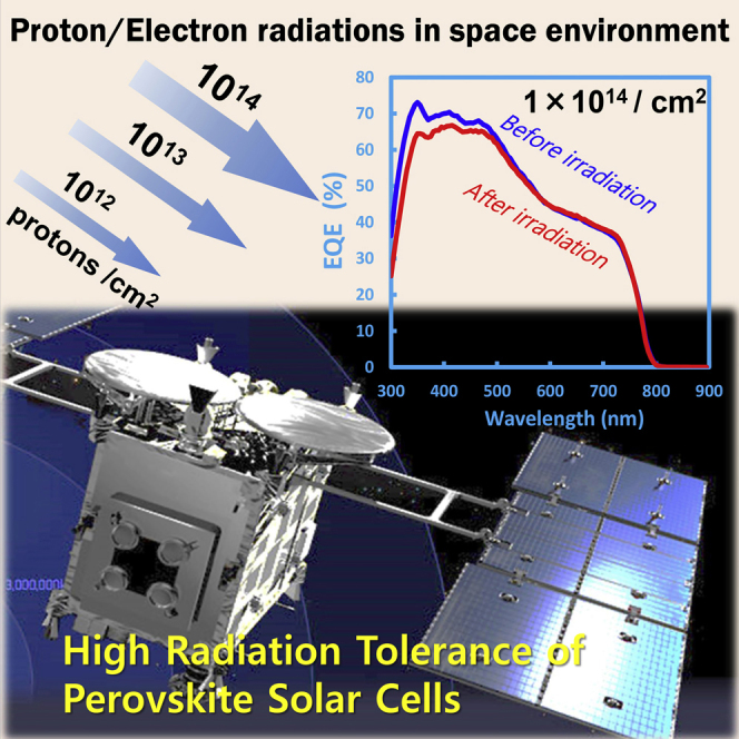
Proton beam (PB) is composed of positively charged hydrogen nucleus with energy ranging from 100 KeV to hundreds of MeV per particle. Because of the greater mass of proton than electron (>2000 times), damage of materials by proton collision occurs at particle fluence generally two orders of magnitude smaller than that of electron. In our tolerance test, PB was irradiated from the Au counterelectrode side to avoid influence of thick glass substrate in PB penetration. This enables to concentrate the proton collision event at the depth of perovskite layer near Au electrode. In perovskite solar cell, stopping position of protons, which is a function of proton energy and density (mass) of material, was determined by the computer program SRIM/TRIM (Stopping and Range of Ions in Matter/Transport of Ions in Matter) using proton energies ranging from 50 KeV to 60 MeV. The result is displayed in Figure 3. A 50-KeV PB incident to the P3HT-MAPbI3 cell gave a proton penetration depth mostly located at the depth of perovskite layer in the multilayered structure. Figure 3B shows how collision rate (number per proton particle) inside the cell is distributed between layered structures. The result corroborates that 50-KeV PB concentrates its collision event at the perovskite layer, whereas high-energy 60-MeV beam mostly penetrates the thin perovskite layer without substantial collision events. With other proton energies investigated, we decided that 50 KeV is best suited to stop proton particles at the perovskite layer. PB tolerance of perovskite (MAPbI3) solar cells has been studied by Lang et al.(2016) and Brus et al.(2017) using a common Methyl [6,6]-phenyl-C61-butyrate (PCBM)-based organic type inverse structure cell. Despite high initial efficiency (11%–12%), both irradiated and non-irradiated (control) cells degraded to 4%–5% during irradiation tests (affected by light soaking), whereas our control cells maintained initial efficiency so that change of cell performance was focused on influence of EB or PB irradiation. In these studies, 68-MeV PB employed showed excellent tolerance of perovskite cell over Si cells to proton impacts up to 1013 particles cm−2. However, based on our analysis, the 68 MeV energy was apparently too high to stop protons at the target perovskite layer. Our thermally durable perovskite cells were subjected to 50 KeV proton irradiation at an incident rate of 3×1011 cm−2s−1. This rate is 107 times larger than the natural value of space environment (low earth orbit) and a highly accelerated condition. Fluence was varied between 1×10¹² and 1×10¹⁵ particles cm−2 (corresponding to 3.3–3300 s as duration time). Here, 1×10¹⁴ particles cm–2 is equivalent to a magnitude in low earth orbit for more than 10 years. The results of photovoltaic performance are summarized in Figures 4 and 5. We found that both of MAPbI3 and FAMAPb(IBr)3 cells have high stability and tolerance in the wide range of PB fluence employed. Figures 4A and 4B show changes of photocurrent EQE spectra before and after PB irradiation at fluences of 1×10¹³ and 1×10¹⁴ particles cm−2, respectively. Higher fluence of 1×10¹⁴ tends to cause non-uniform changes in spectral response of photocurrent. However, PB-induced change was small and photovoltaic performance of MAPbI3 and FAMAPb(IBr)3 cells survived substantially. Figure 5 plots PB-induced changes in JSC, VOC, and PCE against 4 order range of fluences collected for groups of 4 or 5 sample cells. Here, FAMAPb(IBr)3 cell showed a sign of degradation at 1×10¹⁴ particles cm–2 as reflected in EQE spectra (Figure 4B). However, no change was detected in the analysis of X-ray diffraction patterns and none of the cells exhibited color change indicative of PbI2 produced by PB damage (Figure S3).
Figure 3.

SRIM/TRIM Analysis of Proton-Induced Collision Event in Perovskite Solar Cell
(A) A profile of 50 KeV PB penetration depth along the depth of multilayered structure in the MA perovskite cell determined by SRIM/TRIM analysis.
(B) Experimentally detected number of vacancies and defects per angstrom ion when MAPbI3 perovskite solar cells are irradiated by protons with energies of 50 KeV (left) and 60 MeV (right), respectively. Data were presented as mean value of 10,000 times irradiation of proton. See also the cell cross-sectional structure in Figure 1.
Figure 4.

Influence of PB Irradiation on MAPbI3 and FAMAPb(IBr)3 Perovskite Solar Cells Detected by the Change in Photocurrent EQE Action Spectra before and after PB Irradiation
(A) Changes of EQE spectrum for MAPbI3 perovskite cell before and after exposure to PB fluences of 1×10¹³ (left) and 1×10¹⁴ particles cm−2 (right).
(B) Changes of EQE spectrum for FAMAPb(IBr)3 perovskite cell before and after exposure to PB fluences of 1×10¹³ (left) and 1×10¹⁴ particles cm−2 (right). See also Supplemental Information, Figure S3 for observation of color change before and after PB irradiation.
Figure 5.

Changes of Photovoltaic Characteristics (JSC, VOC, Pmax, and PCE) in MAPbI3 (left) and FAMAPb(IBr)3 (right) Perovskite Cells as a Function of PB Fluence
Values are normalized for unity at initial magnitudes. Data are represented as mean value of 4 cells with error bars as distribution of values.
We further investigated the impact of high PB fluence up to 1×10¹⁵ particles cm−2 on FAMAPb(IBr)3 using a group of 10 sample cells. Apparently, the cell was found to start degrading at this extreme dose level. However, to our surprise, some cells could still have photovoltaic activity with half reduction of PCE. As long as our tolerance test of space-aid solar cells is concerned, no solar cells (Si, CIGS, GaAs, etc.) could survive under proton fluence level of 1×10¹⁵ particles cm−2 (Anspaugh, 1989, Anspaugh, 1996, Morita et al., 1997, Sumita et al., 2003, Imaizumi et al., 2017). Our experiments corroborate remarkably high tolerance of perovskite solar cells against space particle irradiation. We consider that the radiation tolerance of perovskite is endowed by the nature of considerably thin absorber film (<500 nm), large carrier diffusion length that exceeds absorber thickness, and defect tolerance of free carriers, all of which can minimize the influence of radiation-induced defects on photovoltaic performance. Our finding endorses usefulness of the perovskite cell for satellite mission.
Methods
All methods can be found in the accompanying Transparent Methods supplemental file.
Acknowledgments
This research was supported by Japan Science and Technology Agency (JST), Advanced Low Carbon Technology (ALCA). T. M. and M. Ikegami thank Dr. Yoshitaka Sanehira for SEM measurements and Dr. Youhei Numata, Dr. Gyumin Kim, Mr. Ashish Kulkarni, Mr. Peerathat Pinpithak, and Mr. Tomoyuki Tobe for their assistance in perovskite device fabrication.
Author Contributions
The experiments were conceived by Y.M., M. Imaizumi., K.H., and T.M. Material synthesis and device fabrication were conducted by H.-W.C. and M. Ikegami. Radiation tolerance measurements were performed by T.O., Y.M., M. Imaizumi., and K.H. Data were analyzed by Y.M., M. Imaizumi., M. Ikegami., and T.M. The results were interpreted by Y.M., M. Imaizumi., M. Ikegami, and T.M. SRIM/TRIM analysis was conducted by Y.M., K.H., and M. Imaizumi. The manuscript was written by Y.M. and T.M.
Declaration of Interests
The authors declare no competing interests.
Published: April 27, 2018
Footnotes
Supplemental Information includes Transparent Methods, three figures, and two tables and can be found with this article online at https://doi.org/10.1016/j.isci.2018.03.020.
Supplemental Information
References
- Anspaugh B.E. JPL Publication; 1989. Solar Cell Radiation Handbook. [Google Scholar]
- Anspaugh B.E. JPL Publication; 1996. GaAs Solar Cell Radiation Handbook. [Google Scholar]
- Brenner T.M., Egger D.A., Kronik L., Hodes G., Cahen D. Hybrid organic–inorganic perovskites: low-cost semiconductors with intriguing charge-transport properties. Nat. Mater. 2016;1:1–16. [Google Scholar]
- Brus V.V., Lang F., Bundesmann J., Seidel S., Denker A., Rech B., Landi G., Neitzert H.C., Rappich J., Nickel N.H. Defect dynamics in proton irradiated CH3NH3PbI3 perovskite solar cells. Adv. Electron. Mater. 2017;3:1600438. [Google Scholar]
- Chen H.-W., Huang T.-Y., Chang T.-H., Sanehira Y., Kung C.-W., Chu C.-W., Ikegami M., Miyasaka T., Ho K.C. Efficiency enhancement of hybrid perovskite solar cells with MEH-PPV hole-transporting layers. Sci. Rep. 2016;6:34319. doi: 10.1038/srep34319. [DOI] [PMC free article] [PubMed] [Google Scholar]
- Cho, B., Davis, J., Hise, L., Korostyshevsky, A., Smith, G., Ley, A.V., Sharps, P., Varghese, T., and Stan, M. (2009). Qualification testing of the ZTJ GaInP2/GaInAs/Ge solar cell to the AIAA S-111 standard, 34th IEEE Photovoltaic Specialists Conference, Philadelphia, PA, USA, 07–12 June (SolAero Technologies Co. ZTJ Space Solar Cell data: http://solaerotech.com/wp-content/uploads/2015/03/ZTJ-Datasheet.pdf.)
- Giacomo F.D., Fakharuddin A., Jose R., Brown T.M. Progress, challenges and perspectives in flexible perovskite solar cells. Energy Environ. Sci. 2016;9:3007–3035. [Google Scholar]
- Green M.A., Ho-Baillie Perovskite solar cells: the birth of a new era in photovoltaics. ACS Energy Lett. 2017;2:822–830. [Google Scholar]
- Imaizumi M., Nakamura T., Takamoto T., Oshima T., Tajima M. Radiation degradation characteristics of component subcells in inverted metamorphic triple-junction solar cells irradiated with electrons and protons. Prog. Photovolt. Res. Appl. 2017;25:161–174. [Google Scholar]
- Jena A.K., Ikegami M., Miyasaka T. Severe morphological deformation of Spiro-OMeTAD in (CH3NH3)PbI3 solar cells at high temperature. ACS Energy Lett. 2017;2:1760–1761. [Google Scholar]
- Kogo A., Ikegami M., Miyasaka T. SnOx-Brookite TiO2 bilayer electron collector for hysteresis-less high efficiency plastic perovskite solar cells fabricated at low process temperature. Chem. Commun. 2016;52:8119–8122. doi: 10.1039/c6cc02589g. [DOI] [PubMed] [Google Scholar]
- Kojima A., Teshima K., Shirai Y., Miyasaka T. Organometal halide perovskites as visible-light sensitizers for photovoltaic cells. J. Am. Chem. Soc. 2009;131:6050–6051. doi: 10.1021/ja809598r. [DOI] [PubMed] [Google Scholar]
- Lang F., Nickel N.H., Bundesmann J., Seidel S., Denker A., Albrecht S., Brus V.V., Rappich J., Rech B., Landi G., Neitzert H.C. Radiation hardness and self-healing of perovskite solar cells. Adv. Mater. 2016;28:8726–8731. doi: 10.1002/adma.201603326. [DOI] [PubMed] [Google Scholar]
- Lee M.M., Teuscher J., Miyasaka T., Murakami T.N., Snaith H.J. Efficient hybrid solar cells based on meso-superstructured organometal halide perovskites. Science. 2012;338:643–647. doi: 10.1126/science.1228604. [DOI] [PubMed] [Google Scholar]
- Li Z., Zhu Z., Chueh C.-C., Luo J., Jen A.K.-Y. Facile thiol-ene thermal crosslinking reaction facilitated hole-transporting layer for highly efficient and stable perovskite solar cells. Adv. Energy Mater. 2016 [Google Scholar]
- Miyasaka T. Perovskite photovoltaics: rare functions of organo lead halide in solar cells and optoelectronic devices. Chem. Lett. 2015;44:720–729. [Google Scholar]
- Mitzi D.B. Synthesis, structure, and properties of organic–inorganic perovskites and related materials. Prog. Inorg. Chem. 1999;48:1–121. doi: 10.1021/ic991048k. [DOI] [PubMed] [Google Scholar]
- Morita Y., Ohshima T., Nashiyama I., Yamamoto Y., Kawasaki O., Matsuda S. Anomalous degradation in silicon solar cells subjected to high-fluence proton and electron irradiations. J. Appl. Phys. 1997;81:6491–6493. [Google Scholar]
- Park N.G., Grätzel M., Miyasaka T., Zhu K., Emery K. Towards stable and commercially available perovskite solar cells. Nat. Energy. 2016;1:16152. [Google Scholar]
- Saliba M., Matsui T., Seo J.Y., Domanski K., Baena J.P.C., Nazeeruddin M.K., Zakeeruddin S.M., Tress W., Abate A., Hagfeldt A., Grätzel M. Cesium-containing triple cation perovskite solar cells: improved stability, reproducibility and high efficiency. Energy Environ. Sci. 2016;9:1989–1997. doi: 10.1039/c5ee03874j. [DOI] [PMC free article] [PubMed] [Google Scholar]
- Saliba M., Matsui T., Domanski K., Seo J.Y., Ummadisingu A., Zakeeruddin S.M., Correa-Baena J.P., Tress W.R., Abate A., Hagfeldt A., Grätzel M. Incorporation of rubidium cations into perovskite solar cells improves photovoltaic performance. Science. 2016;354:206–209. doi: 10.1126/science.aah5557. [DOI] [PubMed] [Google Scholar]
- Sanchez R.S., Mas-Marza E. Light-induced effects on Spiro-OMeTAD films and hybrid lead halide perovskite solar cells. Sol. Energy Mater. Sol. Cells. 2016;158:189–194. [Google Scholar]
- Singh T., Miyasaka T. Stabilizing the efficiency beyond 20% with a mixed cation perovskite solar cell fabricated in ambient air under controlled humidity. Adv. Energy Mater. 2017:1700677. [Google Scholar]
- Smecca E., Numata Y., Deretzis I., Pellegrino G., Boninelli S., Miyasaka T., Magna A.L., Alberti A. Stability of solution-processed MAPbI3 and FAPbI3 layers. Phys. Chem. Chem. Phys. 2016;18:13413–13422. doi: 10.1039/c6cp00721j. [DOI] [PubMed] [Google Scholar]
- Stranks S.D., Eperon G.E., Grancini G., Menelaou C., Alcocer M.J.P., Leijtens T., Herz L.M., Petrozza A., Snaith H.J. Electron-hole diffusion lengths exceeding 1 micrometer in an organometal trihalide perovskite absorber. Science. 2013;342:341–344. doi: 10.1126/science.1243982. [DOI] [PubMed] [Google Scholar]
- Sumita T., Imaizumi M., Matsuda S., Ohshima T., Ohi A., Itoh H. Proton radiation analysis of multi-junction space solar cells. Nucl. Instrum. Methods Phys. Res. B. 2003;206:448–451. [Google Scholar]
- Yamaguchi M., Stephen J.T., Matsuda S., Kawasaki O. Mechanism for the anomalous degradation of Si solar cells induced by high fluence 1MeV electron irradiation. Appl. Phys. Lett. 1996;68:3141. [Google Scholar]
- Yang W.S., Park B.-W., Jung E.H., Jeon N.J., Kim Y.C., Lee D.U., Shin S.S., Seo J., Kim E.K., Noh J.H., Seok S.I. Iodide management in formamidinium-lead-halide–based perovskite layers for efficient solar cells. Science. 2017;356:1376–1379. doi: 10.1126/science.aan2301. [DOI] [PubMed] [Google Scholar]
Associated Data
This section collects any data citations, data availability statements, or supplementary materials included in this article.