

Summary
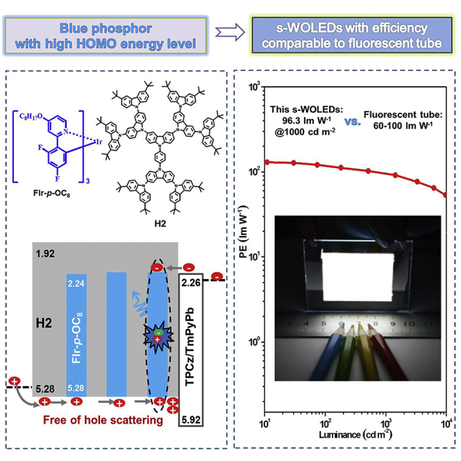
A high-energy-level blue phosphor FIr-p-OC8 has been developed for solution-processed white organic light-emitting diodes (WOLEDs) with comparable fluorescent tube efficiency. Benefiting from the electron-donating nature of the introduced alkoxy, FIr-p-OC8 shows not only efficient blue light but also elevated highest occupied molecular orbital/lowest unoccupied molecular orbital levels to well match the dendritic host H2. Consequently, the hole scattering between FIr-p-OC8 and H2 can be prevented to favor the direct exciton formation on the blue phosphor, leading to reduced driving voltage and thus improved power efficiency. By exploiting this approach, a maximum power efficiency of 68.5 lm W−1 is achieved for FIr-p-OC8-based white devices, slightly declining to 47.0 lm W−1 at a practical luminance of 1,000 cd m−2. This efficiency can be further raised to 96.3 lm W−1 @ 1,000 cd m−2 when a half-sphere is applied to increase light out-coupling. We believe that our results can compete with commercial fluorescent tubes, representing an important progress in solution-processed WOLEDs.
Subject Areas: Organometallic Chemistry, Inorganic Materials, Optoelectronics
Graphical Abstract
Highlights
-
•
High-energy-level blue phosphor FIr-p-OC8 is developed by alkoxyl substitution
-
•
Matched HOMO levels between dendritic host and blue-emitting dopant
-
•
Free of hole scattering to promote direct exciton formation on blue phosphor
-
•
Record-high power efficiency of 96.3 lm W−1 at 1,000 cd m−2 for solution-processed WOLEDs
Organometallic Chemistry; Inorganic Materials; Optoelectronics
Introduction
White organic light-emitting diodes (WOLEDs) have attracted intense academic and industrial attention owing to their potential to replace fluorescent tubes for applications in energy-saving lightings (Kido et al., 1995, Sun et al., 2006, Reineke et al., 2009, Park et al., 2008, Su et al., 2008, Wang et al., 2009, Kamtekar et al., 2010, Chang et al., 2013, Ou et al., 2014, Ding et al., 2015, Zhou et al., 2015, Liu et al., 2016, Wu et al., 2008, Wu et al., 2009, Wu et al., 2016, Huang et al., 2009, Zou et al., 2011, Fu et al., 2012, Zhang et al., 2012, Zhang et al., 2013, Aizawa et al., 2014, Chiba et al., 2015). Nowadays most of the attention is focused on vacuum-deposited WOLEDs (v-WOLEDs) (Ou et al., 2014, Ding et al., 2015, Zhou et al., 2015, Liu et al., 2016, Wu et al., 2016). Since the first report in 1995 (Kido et al., 1995), the power efficiency (PE) of v-WOLEDs has been significantly improved and has surpassed those of the commercial fluorescent tubes (60–100 lm W−1, the threshold for practical applications) (Reineke et al., 2009, Ou et al., 2014, Ding et al., 2015). Nevertheless, solution-processed WOLEDs (s-WOLEDs) are under less investigation, although they are believed to be superior to v-WOLEDs in view of the advantages including low cost, large area, and flexible device fabrication (Wu et al., 2008, Wu et al., 2009, Huang et al., 2009, Zou et al., 2011, Fu et al., 2012, Zhang et al., 2012, Zhang et al., 2013, Aizawa et al., 2014, Chiba et al., 2015). Their PE remains far away from the fluorescent tube efficiency even if transition-metal-containing phosphors are used to harvest both singlet and triplet excitons to increase the external quantum efficiency (EQE) (Wu et al., 2008, Wu et al., 2009, Zou et al., 2011, Fu et al., 2012, Zhang et al., 2012, Zhang et al., 2013, Aizawa et al., 2014, Chiba et al., 2015). Therefore, the accompanying high driving voltage may account for the poor PE of s-WOLEDs because it is directly proportional to the ratio of EQE to driving voltage (PE ∝ EQE/V).
A single emitting layer (EML) device structure (Wu et al., 2008, Wu et al., 2009, Huang et al., 2009, Zou et al., 2011, Fu et al., 2012, Zhang et al., 2012, Zhang et al., 2013, Aizawa et al., 2014), which consists of a host doped with blue and long-wavelength phosphor, is usually adopted in s-WOLEDs since the layer beneath could be dissolved by the solution deposition of a subsequent layer. Considering the negligible contribution from the long-wavelength phosphor with an extremely low doping concentration in EML, the host and blue phosphor are two critical factors that are related to the high driving voltage originating from the limited charge injection and transport. First, a suitable host with a triplet energy higher than that of blue phosphor is desirable to avoid triplet exciton back transfer from the dopant to the host (Ding et al., 2009, Lee and Lee, 2013, Park et al., 2013, Lee et al., 2015, Seino et al., 2014). So an increased driving voltage should be provided to overcome large energy barriers before carriers (holes and/or electrons) are injected into such wide-band-gap host. Second, either the highest occupied molecular orbital (HOMO) level or the lowest unoccupied molecular orbital (LUMO) level of the blue phosphor does not match with those of the host used. The resultant charge trapping or scattering may bring about the enhancement of driving voltage by decreasing the charge transport of the EML (Tsung and So, 2008, Li et al., 2011, Li et al., 2012a, Li et al., 2012b, Li et al., 2014, Schmechel and von Seggern, 2004, Tong et al., 2007, von Malm et al., 2001).
Aiming at low-voltage-driving and thus power-efficient s-WOLEDs, the first challenge is to develop solution-processible host materials that exhibit appropriate energy levels to ensure efficient charge injection without sacrificing high triplet energy. Recently, a dendritic oligocarbazole molecule H2 has been demonstrated as a good host for the blue phosphor iridium(III)[bis(4,6-difluorophenyl)-pyridinato-N,C2]-picolinate (FIrpic) (Ding et al., 2009). When compared with the archetypical high-triplet-energy polymeric host poly(N-vinylcarbazole) (PVK) with a deep HOMO level of −5.9 eV, H2 possesses a triplet energy as high as 2.9 eV and an elevated HOMO level up to −5.28 eV simultaneously. As a result of the reduced hole injection barrier from PVK to H2, the PE of H2-based blue device is improved from 8.3 to 15.4 lm W−1. Further co-doping a small amount of yellow phosphor iridium(III)[5-trifluoromethyl-2-(9,9-diethylfluoren-2-yl)pyridine] (Ir(Flpy-CF3)3) into the EML leads to a promising white light (Zhang et al., 2012), showing a PE of 23.3 lm W−1 at a practical luminance of 1,000 cd m−2. In this case, although the host is well modified to facilitate hole injection, hole transport could be obviously influenced by the associated hole scattering because the HOMO level of FIrpic (−5.64 eV) is much lower than that of H2. To solve this bottleneck, the second challenge is to design novel blue phosphors with high energy levels so as to match with those of the dendritic host. However, this important issue has rarely been addressed to date.
Here we present the realization of power-efficient s-WOLEDs with PE approaching 100 lm W−1 at a luminance of 1,000 cd m−2 by using a newly developed high-energy-level blue phosphor FIr-p-OC8 (Figure 1). Unlike the commonly used FIrpic (−5.64/-2.62 eV), the para substitution of alkoxy group endows FIr-p-OC8 with elevated HOMO/LUMO levels of −5.28/-2.24 eV while maintaining efficient blue emission. When combined with the dendritic host H2 (Figure 3D), the hole scattering between FIr-p-OC8 and H2 can be effectively prevented because of their matched HOMO levels, thus allowing excitons to be formed directly on FIr-p-OC8. With this approach, low driving voltage and high PE have been successfully achieved for the solution-processed white light-emitting device based on FIr-p-OC8, revealing a state-of-art PE of 68.5 lm W−1 at the maximum and 47.0 lm W−1 at 1,000 cd m−2. Also, when a half-sphere is applied to increase the light out-coupling, these efficiencies can be further raised to 130.1 and 96.3 lm W−1, respectively. To our knowledge, such performance is the highest ever reported so far for s-WOLEDs, which could even compete with those of commercial fluorescent tubes.
Figure 1.

Design of High-Energy-Level Blue Phosphors
(A) Molecular structures of blue phosphors (FIrpic, FIr-m-OC8 and FIr-p-OC8).
(B) UV-Vis absorption spectra in dichloromethane (DCM) together with photoluminescent (PL) spectra in toluene (The black circles and arrows indicate the corrsponding vertical axis for each data curves).
(C) PL decay curves in toluene.
(D) Cyclic voltammograms in solution using 0.1M n-Bu4NClO4 as supporting electrolyte at a scan rate of 100 mV s−1.
(E) HOMO/LUMO level alignment of the blue phosphors.
Figure 3.

Analysis of the Hole Scattering-Induced Influence
(A) Working mechanism of FIrpic-based blue device.
(B) Current density-voltage characteristics of FIrpic-based hole-only devices with different doping concentration of 0, 1, 5, and 15 wt.%.
(C) Transient EL decay curves for FIrpic-based blue device with a doping concentration of 15 wt. %.
(D) Working mechanism of FIr-p-OC8-based blue device.
(E) Current density-voltage characteristics of FIr-p-OC8-based hole-only devices with different doping concentration of 0, 1, 5, and 15 wt.%.
(F) Transient EL decay curves for FIr-p-OC8-based blue device with a doping concentration of 15 wt.%.
Results and Discussion
Molecular Design
To tune the energy level of blue phosphors, the alkoxy group with strong electron-donating capability is introduced into the meta and para positions to the N atom in the 2-(2′,4′-difluorophenyl)pyridine ligand, and the corresponding homoleptic Ir complexes FIr-m-OC8 and FIr-p-OC8 are synthesized, respectively (Figure 1A). During the procedure (Scheme S1), a convenient post-modification is adopted and begins with the preparation of an emissive Ir core functionalized with three reactive hydroxyl groups (FIr-m-OH and FIr-p-OH), which subsequently reacts with octyl bromide to give the final Ir complexes. Their detailed synthesis and characterization are provided in the Supplemental Information.
Figures 1B and 1C plot the steady and transient photoluminescence spectra of the complexes in toluene solution, respectively. With respect to FIrpic (λem = 472 nm), as one can see, FIr-m-OC8 displays a red-shifted emission at 481 nm, whereas a hypsochromic shift (λem = 462 nm) is observed for FIr-p-OC8 (Table 1). In addition, the exited state lifetime in toluene solution of FIr-p-OC8 (0.85 μs) is found to be shorter than those of FIrpic (1.02 μs) and FIr-m-OC8 (1.96 μs), in good agreement with the higher photoluminescence quantum yield (PLQY) in toluene solution of FIr-p-OC8 (0.78) than those of FIrpic (0.60) and FIr-m-OC8 (0.23). Most importantly, as estimated from their cyclic voltammetry curves (Figure 1D), the HOMO/LUMO levels are gradually increased from −5.64/-2.62 eV of FIrpic to −5.44/-2.37 eV of FIr-m-OC8 and −5.28/-2.24 eV of FIr-p-OC8 (Figure 1E). The upshift of HOMO/LUMO is in good agreement with the theoretical calculations (Figure S1), indicating that the position and electron-donating effect of the alkoxy substituent can be employed to finely tailor the photophysical and electrochemical properties of blue phosphors.
Table 1.
Summary of Photophysical, Electrochemical, and Thermal Properties for the Dendritic Host and Blue Phosphors
| Material | λabs(logɛ)a (nm) | λemb (nm) | PLQYc | τ(μs)d | Eoxe (V) | Erede (V) | HOMOf (eV) | LUMO (eV) | T1h (eV) | Tm/Td (°C) |
|---|---|---|---|---|---|---|---|---|---|---|
| H2 | 242 (5.5), 268 (5.1), 288 (5.1), 298 (5.2), 350 (4.5) | 391, 408 | – | – | 0.48 | – | −5.28 | −1.91g | 2.86 | −/− |
| FIrpic | 256 (4.7), 381 (3.8), 412 (3.5), 427 (3.3), 456 (2.8) | 472, 499 | 0.60 | 1.02 | 0.84 | −2.18 | −5.64 | −2.62f | 2.63 | ND/330 |
| FIr-m-OC8 | 244 (4.7), 263 (4.6), 323 (4.2), 371 (3.8), 379 (3.7) | 481, 497 | 0.23 | 1.96 | 0.64 | −2.43 | −5.44 | −2.37f | 2.58 | 155/337 |
| FIr-p-OC8 | 265 (4.8), 347 (4.1), 381 (3.9), 417 (3.4), 448 (2.9) | 462, 485 | 0.78 | 0.85 | 0.48 | −2.56 | −5.28 | −2.24f | 2.69 | 222/341 |
Also see Figures S2–S4, and Table S1.
Measured in DCM at 298 K with a concentration of 10−5 M.
Measured in toluene at 298 K with a concentration of 10−5 M.
Measured in degassed toluene at 298 K excited at 350 nm with a concentration of 10−5 M using a calibrated integrating sphere.
Measured in degassed toluene at 298 K, and the lifetimes were obtained by a monoexponential fit of PL decay curves.
Eox is the first oxidation onset measured in DCM, and Ered is the first reduction onset measured in DMF.
The HOMO and LUMO energy levels were calculated according to the equations: HOMO = -e(Eox+ 4.8 V) and LUMO = -e(Ered+ 4.8 V).
The LUMO levels are calculated according to the equation: LUMO = HOMO + Eg, where Eg is the optical bandgap estimated from the absorption onset.
The triplet energy levels were calculated according to the phosphorescence peak wavelength positioned on the shortest wavelength side measured in toluene solution with a concentration of 10−5 M.
Superiority of High-Energy-Level Blue Phosphor
In view of the obtained high-lying HOMO/LUMO levels, blue-shifted emission, high ΦPL, and shorter lifetime, FIr-p-OC8 is anticipated to be a better blue phosphor than FIrpic. To demonstrate this point, two types of monochromic devices are prepared at the same time for comparison: ITO(indium tin oxide)/PEDOT:PSS(poly(ethylenedioxythiophene):poly(styrenesulfonate))/H2:FIrpic/TPCz/TmPyPb/LiF/Al (denoted as device A) and ITO/PEDOT:PSS/H2:FIr-p-OC8/TPCz/TmPyPb/LiF/Al (denoted as device B) (Figure S5). When the doping concentration grows up from 1 wt.% to 15 wt.%, the turn-on voltage for device A is monotonically increased from 3.9 to 4.5 V along with the reduced current density at the same driving voltage (Figure S6 and Table S2). On the contrary, the turn-on voltage for device B is in the range of 3.1–3.3 V, and the current density-voltage (J-V) characteristics remain nearly unchanged, irrespective of the doping concentration. Accordingly, device B exhibits reduced driving voltage and improved PE than device A. As depicted in Figure 2, both the J-V and luminance-voltage (L-V) curves at a 15 wt.% content shift by about 1.5 V toward a negative voltage on going from FIrpic to FIr-p-OC8. Under a luminance of 100 and 1,000 cd m−2, the driving voltages are significantly decreased from 5.6 to 6.3 V to 4.0 and 4.5 V. Meanwhile, the PEs are raised from 17.8 and 16.0 lm W−1 to 26.2 and 20.3 lm W−1.
Figure 2.

Performance Comparison between FIrpic- and FIr-p-OC8-Based Blue Devices with the Same Doping Concentration (15 wt. %)
(A) Current density-voltage-luminance characteristics (The black circles and arrows indicate the corrsponding vertical axis for each data curves).
(B) Power efficiency-luminance characteristics.
Also see Figures S5 and S6, and Table S2.
Given the same configuration, the observed difference of the device performance between FIrpic and FIr-p-OC8 can be reasonably ascribed to their different energy alignments with regard to H2. In device A, holes are injected and transported in H2 but not in FIrpic since FIrpic has a deeper HOMO level than H2 (Figure 3A). On one hand, FIrpic can act as hole scatters and cause an increase of the total transit path and thus the decrease of the hole mobility. As verified by the hole-only devices (Figure 3B), the hole current at the same driving voltage is greatly lowered with increasing content of FIrpic. On the other hand, electrons can be injected from TPCz/TmPyPb either into FIrpic preferentially or into H2 through electrostatic attraction and then trapped by FIrpic as a result of the lower lying LUMO of FIrpic relative to H2. These captured electrons on FIrpic can neither escape from FIrpic due to the large electron-trapping depth between FIrpic and H2 (0.70 eV) nor form the radiative excitons because holes occur scarcely in FIrpic due to the existing hole scattering. Consequently, electrons would be inevitably stored on FIrpic molecules to some extent, which is further confirmed by time-resolved electroluminescence measurements (Liu et al., 2011, Weichsel et al., 2012). As one can see in Figure 3C, a distinct transient overshoot, corresponding to an electron storage, is distinctly observed for device A after voltage turn-off. When a negative postpulse bias is applied from 0 to −3 and −5 V, the overshoot time is gradually shortened, associated with the enhanced overshoot intensity. In other words, the existence of hole scattering in device A would cause both reduced hole mobility and electron accumulation on dopant, which is responsible for the inferior device performance of FIrpic.
In contrast, hole scattering is not present anymore in device B because the HOMO level of FIr-p-OC8 matches well with H2. Holes can hop freely between H2 and FIr-p-OC8, and hole transport is not affected by the doped blue phosphor (Figure 3D). This is consistent with the hole-only devices (Figure 3E), where the hole current is found to be independent of the doping concentration of FIr-p-OC8. Meanwhile, the electrons that are energetically injected from TPCz/TmPyPb to FIr-p-OC8 owing to their close LUMO levels would not accumulate on FIr-p-OC8, but recombine with the holes to generate excitons directly. As shown in Figure 3F, no transient overshoot is detected for device B, implying the vanishment of electron accumulation. Therefore, the unwanted hole scattering can be eliminated in device B to favor the direct exciton generation on the blue phosphors, leading to the reduction of driving voltage and enhancement of PE.
Solution-Processed White Devices
Promoted by the superiority of FIr-p-OC8 to FIrpic in terms of the lower driving voltage and higher PE, FIr-p-OC8 is then used to fabricate power-efficient s-WOLEDs. Considering the fact that the PE of FIr-p-OC8 does not reach the maximum value in the range of 1–15 wt.% (Table S2), the FIr-p-OC8 content doped into H2 is tuned to optimize the monochromic device performance. It is found that the best device performance is obtained at a much higher doping concentration of 25 wt.%, giving a peak PE of 34.2 lm W−1 (37.8 cd A−1, 19.6%) with Commission Internationale de l’Eclairage (CIE) coordinates of (0.15, 0.26) (Figures 4A and S7, Tables 2 and S3). Even at a luminance of 100 and 1,000 cd m−2, the PE still remains at 33.1 and 26.9 lm W−1, respectively, indicative of the gentle PE roll-off. It could be ascribed to the very low driving voltage of only about 3.6/4.1 V at a luminance of 100/1,000 cd m−2. In addition, compared with a device with 15 wt. % FIr-p-OC8, the driving voltage at 1,000 cd m−2 for a device with 25 wt. % FIr-p-OC8 is decreased by about 0.4 V, and the PE is correspondingly increased by about 33%. As discussed above, the formation of excitons directly on blue phosphor is mainly responsible for the efficient blue light after the elimination of hole scattering. Thus the higher content of the blue dopant into H2 could contribute more to this pathway, and result in PE improvement.
Figure 4.

Performance of FIr-p-OC8-Based Blue and White Devices with an EML Composed of H2, 25 wt.%; FIr-p-OC8, x wt.% Ir(Flpy-CF3)3
(A–C) EL spectra at 1,000 cd m−2; current density-voltage-luminance characteristics; and power efficiency as a function of luminance for devices without out-coupling (The black circles and arrows indicate the corrsponding vertical axis for each data curves).
(D–F) EL spectra at 1,000 cd m−2; current density-voltage-luminance characteristics; and power efficiency as a function of luminance for devices with light out-coupling (The black circles and arrows indicate the corrsponding vertical axis for each data curves).
Also see Figures S5 and S7–S15, and Tables S3 and S4.
Table 2.
Summary of Device Performance for FIr-p-OC8-Based Blue and White Light-Emitting Devices with an EML Composed of H2: 25 wt.% and FIr-p-OC8: x wt.% Ir(Flpy-CF3)3
| Content of Ir(Flpy-CF3)3 | Von (V) | Max Performance |
Device Performance at 1000/5000 cd m−2 |
|||||||
|---|---|---|---|---|---|---|---|---|---|---|
| L (cd m−2) | LE (cd A−1) | PE (lm W−1) | EQE (%) | Vd (V) | LE (cd A−1) | PE (lm W−1) | EQE (%) | CIE (x, y) at 1000 cd m−2 | ||
| x = 0 (Without out-coupling) | 2.9 | 17,655 | 37.8 | 34.2 | 19.6 | 4.1/4.7 | 34.9/27.1 | 26.9/17.5 | 18.1/14.1 | (0.15, 0.26) |
| x = 0 (With out-coupling) | 2.9 | 38,580 | 70.9 | 63.0 | 34.2 | 4.1/4.6 | 66.9/56.2 | 50.9/38.6 | 32.2/27.0 | (0.16, 0.28) |
| x = 0.4 wt.% (Without out-coupling) | 2.9 | 23,392 | 60.4 | 59.4 | 21.8 | 4.1/4.6 | 52.7/37.7 | 40.2/25.8 | 19.6/14.5 | (0.34, 0.39) |
| x = 0.4 wt.% (With out-coupling) | 2.8 | 44,177 | 120.3 | 117.5 | 42.8 | 3.9/4.3 | 110.5/85.0 | 88.7/61.9 | 41.0/32.2 | (0.36, 0.40) |
| x = 0.7 wt.% (Without out-coupling) | 2.8 | 23,085 | 69.1 | 68.5 | 23.6 | 4.1/4.6 | 59.7/43.1 | 47.0/29.8 | 20.6/15.4 | (0.43, 0.44) |
| x = 0.7 wt.% (With out-coupling) | 2.8 | 44,485 | 131.5 | 130.1 | 44.6 | 3.9/4.3 | 119.5/95.0 | 96.3/69.0 | 40.9/33.0 | (0.44, 0.44) |
Also see Figures S10 and S13, and Table S4.
Based on such an optimized composition (H2: 25 wt.% FIr-p-OC8), subsequently, an additional yellow phosphor Ir(Flpy-CF3)3 is added into the EML for the fabrication of s-WOLEDs (Figure S5). The absolute concentration of Ir(Flpy-CF3)3 is initially adjusted to be 0.4 wt.% so as to balance the blue and yellow components for the realization of a satisfactory white emission with CIE coordinates of (0.34, 0.39) (Figure 4A), close to the standard white point, viz., (0.33, 0.33). At such a low doping concentration, Ir(Flpy-CF3)3 is considered to have no influence on the device working mechanism, which is evidenced by nearly the same J-V characteristics between monochromic and two-color white lightemitting devices (Figure 4B). Similar to the monochromic device, hole scattering between host and dopant is avoided and most of the excitons are produced directly on the blue phosphor in the white device, followed by a subsequent energy transfer to the yellow phosphor to generate the white light. As a consequence, the advantages of the monochromic device, such as the ultralow driving voltage, high PE, and small efficiency roll-off, could be inherited by the white device. For example, the driving voltage is as low as 2.9, 4.1, and 4.6 V at 1, 1,000 and 5,000 cd m−2, respectively. The maximum PE is 59.4 lm W−1, slightly declining to 40.2 and 25.8 lm W−1 at a luminance of 1,000 and 5,000 cd m−2, respectively (Figure 4C). Further increasing the doping concentration of Ir(Flpy-CF3)3 up to 0.7 wt.% results in a warm white light with CIE coordinates of (0.43, 0.44). Correspondingly, the PE is enhanced to 68.5 lm W−1 at the maximum; 47.0 lm W−1 at 1,000 cd m−2; and 29.8 lm W−1 at 5,000 cd m−2. When compared with FIrpic-based white-light-emitting devices showing hole scattering (23.3 lm W−1 at 1,000 cd m−2) (Zhang et al., 2012), the PE at high luminance is increased by about two-fold for FIr-p-OC8 free of hole scattering. The improvement clearly highlights the importance of high-energy-level blue phosphors in maximizing the PE of solution-processed white-emitting devices by the elimination of hole scattering.
As for the white devices built in a standard substrate-emitting architecture, the light out-coupling efficiency is approximately 20%, and the remaining 80% of the light is trapped in organic and substrate modes. Therefore, similar to the literature report (Reineke et al., 2009), a half-sphere is pasted on the bottom of the ITO glass to unlock the trapped light as much as possible. As one can see in Figure 4D, the adoption of such an out-coupling technique has little effect on the electroluminescent (EL) spectra. The CIE coordinates slightly shift from (0.34, 0.39) and (0.43, 0.44) to (0.36, 0.40) and (0.44, 0.44) for the white devices containing 0.4 wt.% and 0.7 wt.% Ir(Flpy-CF3)3, respectively. Moreover, the luminance at the same driving voltage is found to be significantly increased, albeit the independent current density (Figures 4E and S13A), leading to PE improvement (Figures 4F and S13C). With the white device containing 0.7 wt.% Ir(Flpy-CF3)3 as an example, the maximum luminance is from 23,085 to 44,485 cd m−2 accompanied by the enhanced maximum PE from 68.5 to 130.1 lm W−1 (Table 2). Noticeably, the PE at a high luminance of 1,000 and 5,000 cd m−2 could also reach up to 96.3 and 69.0 lm W−1, respectively. These values are the highest ever reported for s-WOLEDs, which are comparable to those of v-WOLEDs and even competent with the commercial fluorescent tubes (Table 3). Interestingly, the related correlated color temperature and CIE coordinates can be well tuned to satisfy different illumination requirements without considerably sacrificing the PE (Figure S15 and Table S4).
Table 3.
Performance Comparison of the Phosphorescent WOLEDs
| Year | Reference | PE at the Maximum (lm W−1) | PE at 1,000 cd m−2 (lm W−1) | CIE (x, y) |
|---|---|---|---|---|
| s-WOLEDs | ||||
| 2008 | Wu et al., 2008 | 10.0 | – | (0.30, 0.47) |
| 2009 | Huang et al., 2009 | 23.4 | – | (0.38, 0.38) |
| 2009 | Wu et al., 2009 | 20.3 | 16.8 | (0.40, 0.45) |
| 2011 | Zou et al., 2011 | 37.4 | 20.7 | (0.31, 0.50) |
| 2012 | Zhang et al., 2012 | – | 23.3 | (0.38, 0.43) |
| 2013 | Zhang et al., 2013 | – | 22.6 | (0.35, 0.41) |
| 2014 | Aizawa et al., 2014 | 45 | 18 | (0.45, 0.42) |
| 2015 | Wang et al., 2015 | 41.8 | 22.8 | (0.43, 0.43) |
| 2018 | This work | 59.4 (w/o) 117.5 (w/-) |
40.2 88.7 |
(0.34, 0.39) (0.36, 0.40) |
| 2018 | This work | 68.5 (w/o) 130.1 (w/-) |
47 96.3 |
(0.43, 0.44) (0.44, 0.44) |
| v-WOLEDs | ||||
| 2008 | Su et al., 2008 | – | 44 | (0.34, 0.40) |
| 2009 | Reineke et al., 2009 | -- (w/o) -- (w/-) |
33 124 |
(0.45, 0.47) (0.41, 0.49) |
| 2011 | Wang et al., 2011 | 40.7 | 37.1 | (0.42, 0.44) |
| 2013 | Chang et al., 2013 | – | 33.8 | (0.44, 0.46) |
| 2014 | Zhu et al., 2014 | 63.2 | 53.4 | (0.35, 0.42) |
| 2014 | Ou et al., 2014 | 68.8 (w/o) 132.8 (w/-) |
60.0 123.4 |
(0.35, 0.46) (0.35, 0.46) |
| 2015 | Ding et al., 2015 | 64.9 | 49.6 | (0.35, 0.46) |
| 2015 | Zhu et al., 2015 | 46.6 | 41.3 | (0.45, 0.44) |
| 2017 | Wu et al., 2017 | 105.0 | 59.5 | (0.40,0.48) |
w/o, without out-coupling; w/-, with out-coupling.
Conclusion
In summary, we report power-efficient s-WOLEDs with PE approaching 100 lm W−1 at l,000 cd m−2 luminance. This is obtained by newly developing a high-energy-level blue phosphor FIr-p-OC8 in combination with the dendritic host H2, where hole scattering can be eliminated to allow the direct formation of excitons. As a result, the solution-processed white-light-emitting device based on FIr-p-OC8 realizes a record-high PE of 68.5 lm W−1 at the maximum and 47.0 lm W−1 at a practical luminance of 1,000 cd m−2, which can be further improved to 130.1 and 96.3 lm W−1, respectively, under light out-coupling. We believe that our work represents an important progress in s-WOLEDs and demonstrates their bright future in low-cost, large-area, and flexible energy-saving lightings.
Methods
All methods can be found in the accompanying Transparent Methods supplemental file.
Acknowledgments
The authors thank Liping Zhu for assisting transient EL measurement. S.W., B.Z., J.D., Z. X., and L.W. acknowledge financial support from the National Key Basic Research and Development Program of China (973 program, Grant No. 2015CB65001), founded by MOST, and the National Natural Science Foundation of China (Grant Nos. 91333205, 51573183, 51322308, 51473162, 51325303, and 51703223). W.-Y.W. acknowledges financial support from the Hong Kong Polytechnic University (1-ZE1C); Ms Clarea Au for the Endowed Professorship (847S); Areas of Excellence Scheme, University Grants Committee of HKSAR, China (AoE/P-03/08); and Hong Kong Research Grants Council (HKBU 12304715).
Author Contributions
J.D. and L.W. coordinated and directed the study. S.W., B.Z., and J.D. conceived the idea and designed the experiments. S.W. fabricated and characterized the devices. L.Z. synthesized the blue phosphors FIr-m-OC8 and FIr-p-OC8. W.-Y.W. provided the yellow phosphor Ir(Flpy-CF3)3. Z.X. helped to design device structures and took part in discussions about the device results. S.W., B.Z., J.D., L.W., and W.-Y.W. wrote and revised the manuscript.
Declaration of Interests
The authors declare no competing interests.
Published: August 31, 2018
Footnotes
Supplemental Information includes Transparent Methods, 15 figures, 4 tables, and 1 scheme and can be found with this article online at https://doi.org/10.1016/j.isci.2018.07.016.
Contributor Information
Baohua Zhang, Email: bhzhang512@ciac.ac.cn.
Junqiao Ding, Email: junqiaod@ciac.ac.cn.
Wai-Yeung Wong, Email: wai-yeung.wong@polyu.edu.hk.
Supplemental Information
References
- Aizawa N., Pu Y.-J., Watanabe M., Chiba T., Ideta K., Toyota N., Igarashi M., Suzuri Y., Sasabe H., Kido J. Solution-processed multilayer small-molecule light-emitting devices with high-efficiency white-light emission. Nat. Commun. 2014;5:5756. doi: 10.1038/ncomms6756. [DOI] [PubMed] [Google Scholar]
- Chang Y.-L., Yin S., Wang Z., Helander M.G., Qiu J., Chai L., Liu Z., Scholes G.D., Lu Z. Highly efficient warm white organic light-emitting diodes by triplet exciton conversion. Adv. Funct. Mater. 2013;23:705–712. [Google Scholar]
- Chiba T., Pu Y.-J., Kido J. Solution-processed white phosphorescent tandem organic light-emitting devices. Adv. Mater. 2015;27:4681–4687. doi: 10.1002/adma.201501866. [DOI] [PubMed] [Google Scholar]
- Ding J., Zhang B., Lu J., Xie Z., Wang L., Jing X., Wang F. Solution-processable carbazole-based conjugated dendritic hosts for power-efficient blue-electrophosphorescent devices. Adv. Mater. 2009;21:4983–4986. doi: 10.1002/adma.200902328. [DOI] [PubMed] [Google Scholar]
- Ding L., Dong S., Jiang Z., Chen H., Liao L. Orthogonal molecular structure for better host material in blue phosphorescence and larger OLED white lighting panel. Adv. Funct. Mater. 2015;25:645–650. [Google Scholar]
- Fu Q., Chen J., Shi C., Ma D. Solution-processed small molecules as mixed host for highly efficient blue and white phosphorescent organic light-emitting diodes. ACS Appl. Mater. Interfaces. 2012;4:6579–6586. doi: 10.1021/am301703a. [DOI] [PubMed] [Google Scholar]
- Huang F., Shih P.I., Shu C.F., Chi Y., Jen A.K.Y. Highly efficient polymer white-light-emitting diodes based on lithium salts doped electron transporting layer. Adv. Mater. 2009;21:361–365. [Google Scholar]
- Kamtekar K.T., Monkman A.P., Bryce M.R. Recent advances in white organic light-emitting materials and devices (WOLEDs) Adv. Mater. 2010;22:572–582. doi: 10.1002/adma.200902148. [DOI] [PubMed] [Google Scholar]
- Kido J., Kimura M., Nagai K. Multilayer white light-emitting organic electroluminescent device. Science. 1995;267:1332–1334. doi: 10.1126/science.267.5202.1332. [DOI] [PubMed] [Google Scholar]
- Lee C.W., Lee J.Y. High quantum efficiency in solution and vacuum processed blue phosphorescent organic light emitting diodes using a novel benzofuropyridine-based bipolar host material. Adv. Mater. 2013;25:596–600. doi: 10.1002/adma.201203180. [DOI] [PubMed] [Google Scholar]
- Lee J.-H., Cheng S.-H., Yoo S.-J., Shin H., Chang J.-H., Wu C.-I., Wong K.-T., Kim J.-J. An exciplex forming host for highly efficient blue organic light emitting diodes with low driving voltage. Adv. Funct. Mater. 2015;25:361–366. [Google Scholar]
- Li B., Chen J., Zhao Y., Yang D., Ma D. Effects of carrier trapping and scattering on hole transport properties of N,N'-diphenyl-N,N'-bis(1-naphthyl)-1,1'-biphenyl-4,4'-diamine thin films. Org. Electron. 2011;12:974–979. [Google Scholar]
- Li B., Chen J., Yang D., Zhao Y., Ma D. The effects of tris(2-phenylpyridine) iridium on the hole injection and transport properties of 4,4',4'-tri(N-carbazolyl)-triphenylamine thin films. Thin Solid Films. 2012;522:352–356. [Google Scholar]
- Li C., Duan L., Sun Y., Li H., Qiu Y. Charge transport in mixed organic disorder semiconductors: trapping, scattering, and effective energetic disorder. J. Phys. Chem. C. 2012;116:19748–19754. [Google Scholar]
- Li C., Duan L., Li H., Qiu Y. Universal trap effect in carrier transport of disordered organic semiconductors: transition from shallow trapping to deep trapping. J. Phys. Chem. C. 2014;118:10651–10660. [Google Scholar]
- Liu R., Gan Z., Shinar R., Shinar J. Transient electroluminescence spikes in small molecular organic light-emitting diodes. Phys. Rev. B. 2011;83:245302. [Google Scholar]
- Liu B., Nie H., Zhou X., Hu S., Luo D., Gao D., Zou J., Xu M., Wang L., Zhao Z. Manipulation of charge and exciton distribution based on blue aggregation-induced emission fluorophors: a novel concept to achieve high-performance hybrid white organic light-emitting diodes. Adv. Funct. Mater. 2016;26:776–783. [Google Scholar]
- Ou Q.-D., Zhou L., Li Y.-Q., Shen S., Chen J.-D., Li C., Wang Q.-K., Lee S.-T., Tang J.-X. Extremely efficient white organic light-emitting diodes for general lighting. Adv. Funct. Mater. 2014;24:7249–7256. [Google Scholar]
- Park Y.-S., Kang J.-W., Kang D.M., Park J.-W., Kim Y.-H., Kwon S.-K., Kim J.-J. Efficient, color stable white organic light-emitting diode based on high energy level yellowish-green dopants. Adv. Mater. 2008;20:1957–1961. [Google Scholar]
- Park Y.-S., Lee S., Kim K.-H., Kim S.-Y., Lee J.-H., Kim J.-J. Exciplex-forming co-host for organic light-emitting diodes with ultimate efficiency. Adv. Funct. Mater. 2013;23:4914–4920. [Google Scholar]
- Reineke S., Lindner F., Schwartz G., Seidler N., Walzer K., Lüssem B., Leo K. White organic light-emitting diodes with fluorescent tube efficiency. Nature. 2009;459:234–238. doi: 10.1038/nature08003. [DOI] [PubMed] [Google Scholar]
- Schmechel R., von Seggern H. Electronic traps in organic transport layers. Phys. Status Solidi A. 2004;201:1215–1235. [Google Scholar]
- Seino Y., Sasabe H., Pu Y.-J., Kido J. High-performance blue phosphorescent OLEDs using energy transfer from exciplex. Adv. Mater. 2014;26:1612–1616. doi: 10.1002/adma.201304253. [DOI] [PubMed] [Google Scholar]
- Su S., Gonmori E., Sasabe H., Kido J. Highly efficient organic blue- and white-light-emitting devices having a carrier- and exciton-confining structure for reduced efficiency roll-off. Adv. Mater. 2008;20:4189–4194. [Google Scholar]
- Sun Y., Giebink N.C., Kanno H., Ma B., Thompson M.E., Forrest S.R. Management of singlet and triplet excitons for efficient white organic light-emitting devices. Nature. 2006;440:908–912. doi: 10.1038/nature04645. [DOI] [PubMed] [Google Scholar]
- Tong K.L., Tsang S.W., Tsung K.K., Tse S.C., So S.K. Hole transport in molecularly doped naphthyl diamine. J. Appl. Phys. 2007;102:093705. [Google Scholar]
- Tsung K.K., So S.K. Carrier trapping and scattering in amorphous organic hole transporter. Appl. Phys. Lett. 2008;92:103315. [Google Scholar]
- von Malm N., Steiger J., Schmechel R., von Seggern H. Trap engineering in organic hole transport materials. J. Appl. Phys. 2001;89:5559–5563. [Google Scholar]
- Wang Q., Ding J., Ma D., Cheng Y., Wang L., Wang F. Manipulating charges and excitons within a single-host system to accomplish efficiency/CRI/color-stability trade-off for high-performance OWLEDs. Adv. Mater. 2009;21:2397–2401. [Google Scholar]
- Wang Z., Helander M., Qiu J., Puzzo D., Greiner M., Liu Z., Lu Z. Highly simplified phosphorescent organic light emitting diode with > 20% external quantum efficiency at > 10,000 cd/m2. Appl. Phys. Lett. 2011;98:073310. [Google Scholar]
- Wang S., Zhang B., Wang X., Ding J., Xie Z., Wang L. Ultrahigh color-stable, solution-processed, white OLEDs using a dendritic binary host and long-wavelength dopants with different charge trapping depths. Adv. Opt. Mater. 2015;3:1349–1354. [Google Scholar]
- Weichsel C., Burtone L., Reineke S., Hintschich S.I., Gather M.C., Leo K., Lüssem B. Storage of charge carriers on emitter molecules in organic light-emitting diodes. Phys. Rev. B. 2012;86:075204. [Google Scholar]
- Wu H., Zou J., Liu F., Wang L., Mikhailovsky A., Bazan G.C., Yang W., Cao Y. Efficient single active layer electrophosphorescent white polymer light-emitting diodes. Adv. Mater. 2008;20:696–702. [Google Scholar]
- Wu H., Zhou G., Zou J., Ho C.-L., Wong W.-Y., Yang W., Peng J., Cao Y. Efficient polymer white-light-emitting devices for solid-state lighting. Adv. Mater. 2009;21:4181–4184. [Google Scholar]
- Wu S.F., Li S.H., Sun Q., Huang C.C., Fung M.K. Highly efficient white organic light-emitting diodes with ultrathin emissive layers and a spacer-free structure. Sci. Rep. 2016;6:25821. doi: 10.1038/srep25821. [DOI] [PMC free article] [PubMed] [Google Scholar]
- Wu S.F., Li S.H., Wang Y.K., Huang C.C., Sun Q., Liang J.J., Liao L.S., Fung M.K. White organic LED with a luminous efficacy exceeding 100 lm W−1 without light out-coupling enhancement techniques. Adv. Funct. Mater. 2017;27:1701314. [Google Scholar]
- Zhang B., Tan G., Lam C.-S., Yao B., Ho C.-L., Liu L., Xie Z., Wong W.-Y., Ding J., Wang L. High-efficiency single emissive layer white organic light-emitting diodes based on solution-processed dendritic host and new orange-emitting iridium complex. Adv. Mater. 2012;24:1873–1877. doi: 10.1002/adma.201104758. [DOI] [PubMed] [Google Scholar]
- Zhang B., Liu L., Tan G., Yao B., Ho C.-L., Wang S., Ding J., Xie Z., Wong W.-Y., Wang L. Interfacial triplet confinement for achieving efficient solution-processed deep-blue and white electrophosphorescent devices with underestimated poly(N-vinylcarbazole) as the host. J. Mater. Chem. C. 2013;1:4933–4939. [Google Scholar]
- Zhou L., Ou Q.-D., Li Y.-Q., Xiang H.-Y., Xu L.-H., Chen J.-D., Li C., Shen S., Lee S.-T., Tang J.-X. Efficiently releasing the trapped energy flow in white organic light-emitting diodes with multifunctional nanofunnel arrays. Adv. Funct. Mater. 2015;25:2660–2668. [Google Scholar]
- Zhu L., Zhao Y., Zhang H., Chen J., Ma D. Using an ultra-thin non-doped orange emission layer to realize high efficiency white organic light-emitting diodes with low efficiency roll-off. J. Appl. Phys. 2014;115:244512. [Google Scholar]
- Zhu L., Wu Z., Chen J., Ma D. Reduced efficiency roll-off in all-phosphorescent white organic light-emitting diodes with an external quantum efficiency of over 20% J. Mater. Chem. C. 2015;3:3304–3310. [Google Scholar]
- Zou J., Wu H., Lam C.-S., Wang C., Zhu J., Zhong C., Hu S., Ho C.-L., Zhou G.-J., Wu H. Simultaneous optimization of charge-carrier balance and luminous efficacy in highly efficient white polymer light-emitting devices. Adv. Mater. 2011;23:2976–2980. doi: 10.1002/adma.201101130. [DOI] [PubMed] [Google Scholar]
Associated Data
This section collects any data citations, data availability statements, or supplementary materials included in this article.