Abstract
Sky‐blue and blue‐emitting, carbazolyl functionalized, bis‐tridentate Ir(III) phosphors Cz‐1–Cz‐3 with bright emission and short radiative lifetime are successfully synthesized in a one‐pot manner. They exhibit very high photostability against UV–vis irradiation in degassed toluene, versus both green and true‐blue‐emitting reference compounds, i.e., fac‐[Ir(ppy)3] and mer‐[Ir(pmp)3]. Organic light‐emitting diodes (OLEDs) based on Cz‐2 exhibit maximum external quantum efficiency (EQE) of 21.6%, EQE of 15.1% at 100 cd m−2, and with CIEx , y coordinates of (0.17, 0.25). This study provides a conceptual solution to the exceedingly stable and efficient blue phosphor. It is promising that long lifespan blue OLED based on these emitters can be attained with further engineering of devices suitable for commercial application.
Keywords: bis‐tridentate, carbazole, iridium, N‐heterocyclic carbene (NHC), pyrazolate
Organic light‐emitting diodes (OLEDs) are being considered as one most appealing technologies of solid‐state lighting and flat panel display applications.1 The use of this technology requires the employment of light‐emitting materials with three elementary colors, i.e., red, green, and blue. However, development of highly efficient and stable blue emitters remains demanding in comparison to green and red counterparts for which their lower energy gaps make them less susceptible to the formation of highly energetic, hot excited states generated by exciton–polaron and/or exciton–exciton annihilation.2 Although, certain pure organic thermally activated delay fluorescent (TADF) emitters have already showed satisfactory blue CIEx , y chromaticity,3 the long‐lived operational stability has not yet been achieved.4 Similarly, both Pt(II)‐ and Ir(III)‐based emitters have been claimed to display blue CIEx , y chromaticity,5 but has rather limited success in terms of exhibiting good operational lifespan.6
To our understanding, the efficient and stable iridium(III) metal‐based emitters, blue in particular, should possess i) both the robust and rigid framework to avoid conformational distortion upon excitation, as it would facilitate the nonradiative deactivation, ii) strong metal–ligand bonding interaction to destabilize the high‐lying metal‐centered (dd*) excited states, for which the thermal population to these states with repulsive potential energy surface would cause serious quenching of emission,7 iii) shortened radiative lifetime to reduce the population density of the long‐lived triplet excitons in devices, alleviating the exciton–exciton and triplet‐polaron annihilation.8 Based on these considerations, we proposed that the demanded rigid structure can be achieved using the so‐called bis‐tridentate (3 + 3) coordination architecture, which deems to be more stable than the tris‐bidentate (2 + 2 + 2) design presented in the traditional blue emitters such as FIrpic,9 MS2,10 and [Ir(fdpt)3].11 For fulfilling the second criterion, the N‐heterocyclic carbene (NHC) is employed as the preferred donor versus the N‐donor such as pyridine and azolate in assembling the demanded metal emitter, as the former is known to exert more destabilized lowest unoccupied molecular orbital (LUMO) and simultaneously has greater ligand field strength.12 Third, decreasing the ligand‐to‐ligand charge transfer (LLCT) and intraligand charge transfer contribution, but increasing metal‐to‐ligand charge transfer (MLCT) characters could reduce the emission radiative lifetime due to the heavy metal atom induced spin–orbit coupling.13 These can be achieved by strategically enriching the electron density of the central metal atom. In this communication, very stable and highly efficient blue‐emitting bis‐tridentate Ir(III) complexes are synthesized according to these three fundamental principles.
The bis‐tridentate Ir(III) complexes have been independently reported by Williams and co‐workers,14 De Cola and co‐workers,15 and Esteruelas et al.16 However, inferior emission efficiency and lack of color tunability were the major weaknesses encountered to these earlier researches. To circumvent these obstacles, we set forth preparation of bis‐tridentate Ir(III) complexes using both pincer dicarbene and functional 6‐pyrazolyl‐2‐phenylpyridine (pzyph) as the ancillary and chromophoric chelates, respectively.17 They were synthesized in a one‐pot manner, i.e., heating of a 1:1:1 mixture of IrCl3·3H2O, carbene pincer pro‐chelate, pzyph chelate, and excess of potassium acetate in propionic acid.18 The added metal acetate works as a cyclometalation promoter via a sequence of concerted metalation and deprotonation reaction.19 Representative sky‐blue and blue‐emitting Ir(III) complexes [Ir(mimf)(pzyphF)] (SB) and [Ir(mimb)(pzytBOhF)] (Px‐5) were obtained (cf. Scheme 1 ), for which the prime difference in structure was the possession of an oxygen spacer in pzytBOhF chelate of Px‐5. It disrupts the effective π‐conjugation and raises the ππ* energy gap versus that of the parent pzyph chelate in SB. Nevertheless, both Ir(III) emitters showed excellent emission efficiency, i.e., 95% in doped 9‐(3‐(9H‐carbazol‐9‐yl)phenyl)‐9H‐carbazole‐3‐carbonitrile (mCPCN) host for SB and 91% in doped DPEPO (bis[2‐(diphenylphosphino)phenyl]ether oxide) host for Px‐5, and afforded blue‐emitting OLEDs with maximum external quantum efficiency (EQE) and with CIEx , y coordinates of 27.0% and (0.18, 0.40), and 20.7% and (0.15, 0.17), respectively.18
Scheme 1.
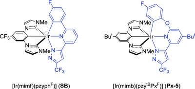
Structure of the representative bis‐tridentate Ir(III) phosphors SB and Px‐5.
Recently, we were inspired by a report on the bond dissociation energy (BDE) of organic materials for optoelectronics,20 which indicated that the strong C(sp2)—N(sp2) bonding interaction in carbazolyl derivatives is helpful in providing greater stability in phosphorescence organic light‐emitting diodes (PhOLEDs). Therefore, we were encouraged to employ the carbazolyl fragment as the replacement of original phenoxy group in the class of pzyph chelate. The structural drawing of [(pzytBCzF6)H2] is depicted in Scheme 2 , and its preparation follows a three‐step procedure. First, coupling of 2‐bromo‐4‐tert‐butyl‐6‐acetylpyridine and 3,6‐bis(trifluoromethyl)‐9H‐carbazole21 afforded 9‐(4‐tert‐butyl‐6‐acetylpyridin‐2‐yl)‐3,6‐bis‐(trifluoromethyl)‐9H‐carbazole. It was next subject to Claisen condensation with ethyl trifluoroacetate, followed by hydrazine cyclization to yield tridentate chelate [(pzytBCzF6)H2]. The schematic reaction diagram, employed chemicals, and detailed conditions are depicted in the Supporting Information. Additionally, three dicarbene pincer ancillaries, i.e., [(mimb)H3·(PF6)2], [(mimf)H3·(PF6)2], and [(pimf)H3·(PF6)2], each with methyl (m) or isopropyl (p) substituent on imidazolium (im) fragment and tert‐butyl (b) or trifluoromethyl (f) substituent at the central phenyl group, were selected for tuning both the steric and electronic properties. Next, the Ir(III) complexes Cz‐1–Cz‐3 (Scheme 3 ) were obtained by heating a mixture of both chelates, IrCl3·3H2O and K2CO3 in propionic acid. The single crystal X‐ray diffraction study on a parent carbazolyl complex [Ir(mimb)(pzytBCz)] (Cz‐0) was also conducted to confirm the structures, cf. data depicted in ESI. Scheme 3 depicted the structural drawings of these Ir(III) metal complexes Cz‐1–Cz‐3. Importantly, we have selected dual CF3 substituents instead of fluoro groups in functionalizing the carbazolyl appendage of Ir(III) complexes Cz‐1–Cz‐3, for avoiding the known defluorination reaction of C(aryl)‐F entity.22
Scheme 2.
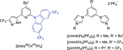
Drawings of the studied chromophoric chelates (left) dicarbene pincer (right).
Scheme 3.
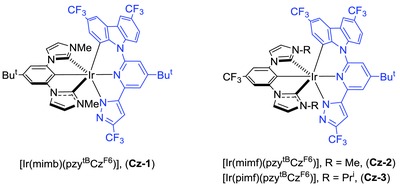
Molecular structure of the studied Ir(III) phosphors Cz‐1–Cz‐3.
UV–vis absorption and emission spectra were recorded in CH2Cl2 solution and the data were provided in Figure 1 and Table 1 , respectively. The intense absorption above 330 nm rooted from ligand‐centered ππ* transition, while the absorption at the longer wavelength region 370–450 nm stemmed from both MLCT transitions in singlet and triplet manifolds, respectively. The structureless emission profile of complexes Cz‐1–Cz‐3 was recorded with peak max. at 486, 473, and 476 nm, and nearly unitary photoluminescence quantum yield (PLQY,Φ) was observed for Cz‐1, and turned slightly low to ≈83% for both Cz‐2 and Cz‐3 in degassed CH2Cl2 at room temperature (RT). Surprisingly, the radiative lifetime (τrad) of emitters Cz‐1–Cz‐3 (2.77–3.80 µs) was sufficiently shorter than the previously reported Ir(III) reference complexes SB and Px‐5 (τrad = 5.41 and 12.0 µs),17, 18 manifesting the dominant charge transfer (i.e., both MLCT and LLCT) contribution in these carbazolyl coordinated Ir(III) complexes.
Figure 1.
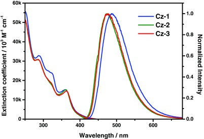
UV–vis absorption and normalized emission spectra of Ir(III) complexes Cz‐1–Cz‐3 recorded in CH2Cl2 solution at RT.
Table 1.
Essential photophysical and relevant data of Ir(III) complexes Cz‐1–Cz‐3
| Abs. λmax [nm] (ε × 103)a) | Em λmax [nm]a) | Φ [%]a), b) | Φ [%]c) | τobs [µs]a) | τr [µs]a) | FWHMd) | E ox ½ (ΔE p) [V]e) | E re pc [V]e) | T d [°C]f) | |
|---|---|---|---|---|---|---|---|---|---|---|
| Cz‐1 | 289(33), 324.5(24), 358(15) | 486 | 100 | 80.3 | 2.77 | 2.77 | 3420 | 0.55 (0.09) | −2.98 | 423 |
| Cz‐2 | 287(31), 361(15) | 473 | 83.5 | 86.9 | 3.20 | 3.83 | 3440 | 0.69 (0.08) | −2.81 | 448 |
| Cz‐3 | 287(31), 322(19), 363.5(15) | 476 | 82.7 | 95.6 | 2.7 | 3.26 | 3400 | 0.68 (0.09) | −2.79 | 386 |
All photophysical data were recorded in CH2Cl2 with a conc. of 10−5 M at RT, ε is in M −1 cm−1
Emission was measured with excitation at 375 nm and in reference to Coumarin 102 in MeOH (Φ = 80%)
Measured in doped film (10 wt% in DPEPO matrix)
Full width at half‐maxima of PL in cm−1
E ½ = [(E pa + E pc)/2] and ΔE p = |E pa − E pc| in V, while E pa and E pc are defined as the anodic and cathodic peak potentials referenced to Fc+/Fc
T d is the temperature with 5% of weight loss in thermogravimetric analysis.
Also conducted was the computational approach based on time‐dependent density functional theory (TD‐DFT) at the B3LYP/LANL2DZ (Ir) and B3LYP/6‐31g(d,p) (H, C, N, F, Cl) levels using CH2Cl2 as the solvent (see Supporting Information for detail). The calculated energy in terms of wavelengths and assignments of each electronic transition of Ir(III) complexes Cz‐1–Cz‐3 are listed in Table 2 and Tables S1–S3 in the Supporting Information. Figure 2 and Figures S2–S4 in the Supporting Information depict the frontier orbitals involved in the lower‐lying transitions. The calculated wavelengths of the S0 → S1 optical transition for Cz‐1: 385 nm, Cz‐2: 377 nm, and Cz‐3: 379 nm were close to the observed onsets of the experimental absorption peaks depicted in Figure 1. The calculated S0 → T1 transition wavelengths for Cz‐1: 421 nm, Cz‐2: 417 nm, and Cz‐3: 418 nm were also in good agreement with the trend of the onset of their phosphorescence spectra in Figure 1. Moreover, after geometry optimization, the calculated wavelengths of the T1 → S0 emission transitions were at 527, 513, and 510 nm for Cz‐1, Cz‐2, and Cz‐3, respectively. These values are ≈4–4.5 kcal mol−1 lower in energy than that of the experimentally acquired emission peak wavelengths (see Figure 1), which is common if one considers that the computational approach is subject to few kcal mol−1 uncertainty, depending on the theoretical levels and basis sets being applied. Nevertheless, the trend of energy gap obtained by the theoretical approach is consistent with that of the experimental result. Therefore, the current TD‐DFT simulation works well in predicting the lowest Franck–Condon transition for both absorption and emission based on the optimized ground state (S0) structure for the studied Ir(III) complexes.
Table 2.
The calculated wavelengths, transition probabilities and main charge characters of the lowest optical transitions S1 and T1 for Ir(III) complexes Cz‐1–Cz‐3 in CH2Cl2 solution
| Complex | State | λ [nm] | f | Main assignments | MLCT |
|---|---|---|---|---|---|
| Cz‐1 | T1 | 421.7 | 0 | HOMO → LUMO (43%) | 21.60% |
| S1 | 384.9 | 0.0405 | HOMO → LUMO (97%) | 29.94% | |
| Cz‐2 | T1 | 417.5 | 0 | HOMO → LUMO (33%) | 22.38% |
| S1 | 377.4 | 0.0552 | HOMO → LUMO (98%) | 28.09% | |
| Cz‐3 | T1 | 418.5 | 0 | HOMO → LUMO (34%) | 22.29% |
| S1 | 379.4 | 0.0497 | HOMO → LUMO (98%) | 28.77% |
Figure 2.
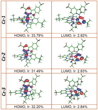
Frontier molecular orbitals for the ground state S0 of Ir(III) complexes Cz‐1–Cz‐3 in CH2Cl2. “Ir” indicates the relative electron density distribution at the iridium atom.
According to the calculation (see Figure 2, Figures S2–S4, Supporting Information and Table 2 and Tables S1–S3, Supporting Information), both S0 → S1 (absorption) and T1 → S0 (emission) transition for Cz‐1–Cz‐3 mainly involves highest occupied molecular orbital (HOMO) and LUMO, in which the electron density distributions of HOMO are mainly localized at the central Ir atom (25–33%) and carbazolyl fragment, while LUMO are mostly distributed at the central pyridine of 2‐carbazolyl‐6‐pyrazolylpyridine fragment and very few at the central Ir(III) atom (1–4%). Since we are focusing on the emission property, for more detail, the T1 → S0 transition for Cz‐1 is mainly assigned to LUMO → HOMO (76%) with minor LUMO → HOMO‐2 (13%). For complex Cz‐2, the T1 → S0 transition is assigned to mainly LUMO → HOMO (65%) with minor LUMO → HOMO‐1 (12%) and LUMO → HOMO‐3 (11%) contribution. For complex Cz‐3, the T1 → S0 emissive transition is assigned to mainly LUMO → HOMO (79%) and minor LUMO → HOMO‐1 (9%). Note that HOMO‐1 (Cz‐2 and Cz‐3), HOMO‐2 (Cz‐1), and HOMO‐3 (Cz‐2) for Cz‐1–Cz‐3 are mainly located at Ir atom, 3‐methylimidazolium and pyrazolyl fragments. Therefore, the T1 → S0 transitions for Cz‐1–Cz‐3 are assigned to MLCT (20–26%) mixed with LLCT. The significant MLCT percentage (>20%) implies fast S1 → T1 (or Tm, m > 1) intersystem crossing, resulting solely in the phosphorescence. This also supports the deduced fast radiative decay rate constant for Cz‐1–Cz‐3 (vide supra, Table 1) due to the enhancement of spin–orbit coupling.
To confirm this theoretical interpretation, cyclic voltammetry was conducted and showed the reversible oxidation at the metal center and irreversible reduction at the coordinated chelate, for which the graphic and numerical data are depicted in Figure S5 in the Supporting Information and Table 1. The anodic shifts of all electrochemical potentials were observed for Cz‐2 and Cz‐3 versus that of Cz‐1, which are attributed to the electron withdrawing property of CF3 group in Cz‐2 and Cz‐3 versus that of electron donating tert‐butyl Cz‐1 group in on the carbene pincer chelate.
As for the stability, thermal gravimetric analysis data illustrated in Table 1 showed T d of Cz‐1–Cz‐3 exceeding 380 °C, which are common to most Ir(III) emitters documented in literature. However, the hot excited states generated by triplet–triplet annihilation of blue emitters possess an energy of ≈6 eV,23 meaning that these T d concepts are not suitable in estimating the material stability of blue emitters. To cope with this deficiency and provide better assessment on material stability, there are a number of literature reports on the use of either 400 nm LED24 or UV irradiation25 to test photostability of OLED emitters in solution and in a solid organic matrix. The photostabilities studies of bis‐tridentate Ir(III) complexes remain rare in comparison to the corresponding tris‐bidentate phosphors. Within this context, we attempted similar photodegradation experiment for Cz‐1–Cz‐3 in deaerated toluene using the standard Atlas Suntest CPS+ Xenon Test Instrument. Figure 3 provides the plot of ln(A t/A 0) versus irradiation time of Ir(III) emitters Cz‐1–Cz‐3. For a fair comparison, the relevant data for [fac‐Ir(ppy)3]26 and [mer‐Ir(pmp)3]27 that are known to be the best green and true‐blue emitters, are also shown in Figure 3. From this diagram, the rate constant of photodegradation was estimated to be 1.9, 2.8, and 2.5 × 10⁻³ h−1 for Cz‐1, Cz‐2, and Cz‐3, and 2.6 and 12 × 10−3 h−1 for [fac‐Ir(ppy)3] and [mer‐Ir(pmp)3], using the integrated first‐order rate law:
| (1) |
Figure 3.
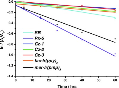
Photodegradation responses of Ir(III) emitters SB, Px‐5, Cz‐1–Cz‐3, [fac‐Ir(ppy)3], and [mer‐Ir(pmp)3], for which all samples were dissolved in deaerated toluene, placed in argon‐filled PL cuvette, followed by the simulated solar irradiation at 620 W m−2 and 35 °C.
These rate constants clearly verified the superior photostability of the bis‐tridentate emitters Cz‐1–Cz‐3, for which that data are comparable to that of the green‐emitting [fac‐Ir(ppy)3], but much superior to that of the true‐blue‐emitting [mer‐Ir(pmp)3] under the identical condition examined. These experimental results also corroborate the theoretical studies showing that 3 + 3 iridium skeleton can afford higher metal–ligand BDE than that of the 2 + 2 + 2 system.23 Moreover, the test also shows that the rate of photodegradation is also slower than that of SB and Px‐5 possessing bis‐tridentate ligands (cf. 5.0 and 16 × 10−3 h−1). We thus propose that the carbazole moiety of the (pzytBCzF6) ligand forms a six‐membered nitrogen‐containing metallacycle in Cz‐1–Cz‐3, which is more stable than that of the corresponding metallacycle made by the phenylpyridine of pzyph for SB and the phenoxypyridine of pzyOh for Px‐5 due to both the higher ligand field strength and robustly chelating framework.
In view of the remarkable photophysical properties of Cz‐1, Cz‐2, and Cz‐3, these emitters were next co‐deposited in DPEPO (T 1 = 3.3 eV) matrix to evaluate their solid‐state luminescence properties.28 In the thin film states (10 wt% in DPEPO), PLQYs of 80.3%, 86.9%, and 95.6% and transition PL decays of 2.95, 3.80, and 3.07 µs were observed for Cz‐1, Cz‐2, and Cz‐3, respectively (cf. Figure S7, Supporting Information). Accordingly, OLEDs with configuration of ITO/MoO3 (1 nm)/TCTA (30 nm)/mCP (10 nm)/DPEPO: Ir(III) emitters at 10 wt% (35 nm)/3TPYMB (50 nm)/LiF (1 nm)/Al (120 nm) were fabricated to assess their electroluminescence performances. Herein, both TCTA (4,4′,4″‐ tris(carbazol‐9‐yl)‐triphenylamine) and mCP (1,3‐di(9H‐carbazol‐9‐yl)benzene) were served as the hole transporting materials and 3TPYMB (tris(2,4,6‐trimethyl‐3‐(pyridin‐3‐yl)phenyl)borane) as the electron transporting layer. As shown in Figure 4 and Table 3 , device Cz‐1 displays sky‐blue emission with peak efficiencies (EQE: 19.6%; CE: 39.5 cd A−1; PE: 37.6 lm W−1; Commission Internationale de l'éclairage (CIE) coordinates of (0.19, 0.34)), while the Cz‐2‐ and Cz‐3‐based devices exhibited the blue emission and impressive performances, with max. EQE of 21.6% and 19.6%, CE of 31.7 and 33.8 cd A−1, PE of 29.3 and 31.2 lm W−1, and CIEx , y coordinates of (0.17, 0.25) and (0.17, 0.26) respectively. These characteristics are clearly superior to those displayed by other relevant bis‐tridentate Ir(III) emitters18, 29 and fall in the ranking column of typical tris‐bidentate blue‐emitting Ir(III) phosphors.30 The recorded CIE coordinates are still deviated from the NTSC blue standard (0.14, 0.08), e.g. National Television System Committee USA. However, this shortcoming can be fixed by employment of microcavity effect and/or using color filter in commercial OLEDs.
Figure 4.
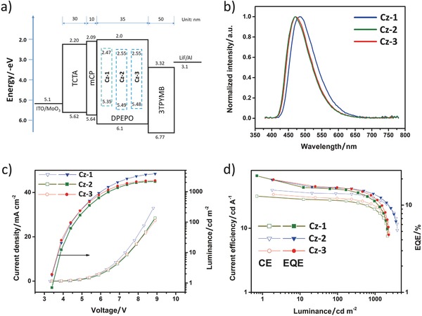
Uniformly doped blue‐emitting OLEDs: a) device diagram and energy levels of used materials, b) EL spectra of devices, c) current density–voltage–luminescence characteristics, and d) plots of current efficiency–luminance–EQE.
Table 3.
Key performance data for the OLED devices
| Emitter | Device types | V on [V] | λEL [nm] | CEa) [cd A−1] | PEa) [lm W−1] | EQEa) [%] | CIEx , y b) |
|---|---|---|---|---|---|---|---|
| Cz‐1 | Uniform | 3.3 | 484 | 39.5, 34.7, 29.1 | 37.6, 24.3, 15.1 | 19.6, 15.5, 12.9 | 0.19, 0.34 |
| Graded | 3.3 | 484 | 41.3, 36.2, 32.0 | 39.3, 24.3, 16.0 | 21.5, 16.5, 14.2 | 0.19, 0.34 | |
| Cz‐2 | Uniform | 3.5 | 468 | 31.7, 27.1, 19.9 | 29.3, 17.8, 9.80 | 21.6, 15.1, 11.0 | 0.17, 0.25 |
| Graded | 3.5 | 468 | 32.5, 30.8, 24.0 | 29.1, 20.3, 11.6 | 21.0, 17.1, 13.2 | 0.17, 0.25 | |
| Cz‐3 | Uniform | 3.4 | 472 | 33.8, 29.4, 21.5 | 31.2, 21.0, 10.6 | 19.6, 15.9, 11.7 | 0.17, 0.26 |
| Graded | 3.5 | 472 | 32.7, 32.1, 25.8 | 27.6, 21.3, 12.5 | 19.5, 17.7, 14.0 | 0.17, 0.26 |
Data at max. and @ 100 and 1000 cd m−2, respectively
@ 100 cd m−2. Device structure: uniformly doped: ITO/MoO3 (1 nm)/TCTA (30 nm)/mCP (10 nm)/DPEPO: 10 wt% dopant (35 nm)/3TPYMB (50 nm)/LiF (1 nm)/Al (120 nm); graded doping: ITO/MoO3 (1 nm)/TCTA (30 nm)/mCP (10 nm)/DPEPO: 15–6 wt% dopant (40 nm)/ 3TPYMB (50 nm)/LiF (1 nm)/Al (120 nm).
However, serious efficiency roll‐off was obtained as increasing luminance (Figure 4 and Table 3), especially at above 1000 cd m−2, which seems contradicting the better photophysical robustness of emitters. However, it should be noted that the chemical stability is not the solely factor in determining the OLED stability and efficiency roll‐off. Other device parameters such as the exciton interaction, exciton–polaron interaction, field‐induced quenching, and charge carriers imbalance also need to be considered.31 In an effort to unveil this efficiency roll‐off, a 2 nm thick, red‐emitting [Ir(piq)2(acac)] dopant was co‐deposited to the emitting layer, at a conc. of 2 wt% but with variable distances (x = 10, 15, and 20 nm) from the emitting layer (EML)/mCP interface.32 As shown in Figure S8 in the Supporting Information, the electroluminescence decreases with increase of x, indicating the close association of the EML/mCP interface and recombination zone (RZ). Furthermore, the red luminescence of device with x = 10 nm turned lowered upon increasing current and driving voltage, meaning that the RZ is further shifting closer to the EML/mCP interface.[[qv: 4c,32,33]] Therefore, in this case, the poor carrier balance in EML has resulted in a narrowed RZ and with highly concentrated excitons, causing the inferior efficiency roll‐off. This problem can be partially alleviated by adapting gradient‐doping technique,27 as shown in Figure S9 in the Supporting Information. For completely resolving this undesirable issue, bipolar host material with T 1 > 3.00 eV34 is needed to prevent the possible leakage of excitons into the adjacent mCP layer, which has a triplet energy of 2.9 eV and is known to contribute considerably to the efficiency roll‐off observed in many TADF‐based true‐blue‐emitting OLEDs.[[qv: 3b,35]]
In conclusion, stability remains to be one key issue for the development of robust and efficient blue‐emitting OLEDs, for which both the material‐related and the extrinsic fabrication issues were considered to be two main factors that gave the undesirable fast device degradation. The high photostability displayed by these new bis‐tridentate Ir(III) emitters Cz‐1–Cz‐3 mainly eliminates the material‐related factor. This, together with the decent OLED architecture to optimize and/or balance the carrier transport and stability of hole and electron transporting materials, would eventually provide a solution aimed at the long lifespan blue‐emitting OLED phosphors for commercial applications.
Conflict of Interest
The authors declare no conflict of interest.
Supporting information
Supplementary
Acknowledgements
H.‐H.K. and Z.‐l.Z. contribute equally to this work. This work was supported by the funding from Ministry of Science and Technology (MOST) of Taiwan, featured areas research program within the framework of the Higher Education Sprout Project administrated by Ministry of Education (MOE) of Taiwan, and City University of Hong Kong, Hong Kong SAR. The authors are grateful to the National Center for the High‐performance Computing (NCHC) of Taiwan for the valuable computer time and facilities.
Kuo H.‐H., Zhu Z.‐l., Lee C.‐S., Chen Y.‐K., Liu S.‐H., Chou P.‐T., Jen A. K.‐Y., Chi Y., Adv. Sci. 2018, 5, 1800846 10.1002/advs.201800846
Contributor Information
Chun‐Sing Lee, Email: c.s.lee@cityu.edu.hk.
Pi‐Tai Chou, Email: chop@ntu.edu.tw.
Alex K.‐Y. Jen, Email: alexjen@cityu.edu.hk.
Yun Chi, Email: ychi@mx.nthu.edu.tw, Email: yunchi@cityu.edu.hk.
References
- 1.a) Sasabe H., Kido J., Chem. Mater. 2011, 23, 621; [Google Scholar]; b) Yook K. S., Lee J. Y., Adv. Mater. 2012, 24, 3169; [DOI] [PubMed] [Google Scholar]; c) Adachi C., Jpn. J. Appl. Phys. 2014, 53, 060101; [Google Scholar]; d) Xu R.‐P., Li Y.‐Q., Tang J.‐X., J. Mater. Chem. C 2016, 4, 9116. [Google Scholar]
- 2. Lee J., Jeong C., Batagoda T., Coburn C., Thompson M. E., Forrest S. R., Nat. Commun. 2017, 8, 15566. [DOI] [PMC free article] [PubMed] [Google Scholar]
- 3.a) Wong M. Y., Zysman‐Colman E., Adv. Mater. 2017, 29, 1605444; [DOI] [PubMed] [Google Scholar]; b) Chan C.‐Y., Cui L.‐S., Kim J. U., Nakanotani H., Adachi C., Adv. Funct. Mater. 2018, 28, 1706023. [Google Scholar]
- 4.a) Scholz S., Kondakov D., Lüssem B., Leo K., Chem. Rev. 2015, 115, 8449; [DOI] [PubMed] [Google Scholar]; b) Furukawa T., Nakanotani H., Inoue M., Adachi C., Sci. Rep. 2015, 5, 8429; [DOI] [PMC free article] [PubMed] [Google Scholar]; c) Zhao F., Wei Y., Xu H., Chen D., Ahamad T., Alshehri S., Pei Q., Ma D., Mater. Horiz. 2017, 4, 641. [Google Scholar]
- 5.a) Im Y., Byun S. Y., Kim J. H., Lee D. R., Oh C. S., Yook K. S., Lee J. Y., Adv. Funct. Mater. 2017, 27, 1603007; [Google Scholar]; b) Li G., Fleetham T., Turner E., Hang X.‐C., Li J., Adv. Opt. Mater. 2015, 3, 390; [Google Scholar]; c) Yang X., Xu X., Zhou G., J. Mater. Chem. C 2015, 3, 913; [Google Scholar]; d) Hang X.‐C., Fleetham T., Turner E., Brooks J., Li J., Angew. Chem., Int. Ed. 2013, 52, 6753. [DOI] [PubMed] [Google Scholar]
- 6.a) Cho H., Lee J., Lee J.‐I., Cho N. S., Park J. H., Lee J. Y., Kang Y., Org. Electron. 2016, 34, 91; [Google Scholar]; b) Fleetham T. B., Huang L., Klimes K., Brooks J., Li J., Chem. Mater. 2016, 28, 3276; [Google Scholar]; c) Zhu Z.‐Q., Klimes K., Holloway S., Li J., Adv. Mater. 2017, 29, 1605002; [DOI] [PubMed] [Google Scholar]; d) Byeon S. Y., Han S. H., Lee J. Y., Adv. Opt. Mater. 2017, 5, 1700387; [Google Scholar]; e) Kim M., Lee I.‐S. H., Lee J.‐Y., Han S. H., Park K.‐M., Kang Y., J. Ind. Eng. Chem. 2018, 58, 386. [Google Scholar]
- 7. Kuei C.‐Y., Liu S.‐H., Chou P.‐T., Lee G.‐H., Chi Y., Dalton Trans. 2016, 45, 15364. [DOI] [PubMed] [Google Scholar]
- 8. Freidzon A. Y., Safonov A. A., Bagaturyants A. A., Krasikov D. N., Potapkin B. V., Osipov A. A., Yakubovich A. V., Kwon O., J. Phys. Chem. C 2017, 121, 22422. [Google Scholar]
- 9. Baranoff E. D., Curchod B., Dalton Trans. 2015, 44, 8318. [DOI] [PubMed] [Google Scholar]
- 10. Sarma M., Tsai W.‐L., Lee W.‐K., Chi Y., Wu C.‐C., Liu S.‐H., Chou P.‐T., Wong K.‐T., Chem 2017, 3, 461. [Google Scholar]
- 11. Li X., Zhang J., Zhao Z., Wang L., Yang H., Chang Q., Jiang N., Liu Z., Bian Z., Liu W., Lu Z., Huang C., Adv. Mater. 2018, 30, 1705005. [DOI] [PubMed] [Google Scholar]
- 12.a) Sajoto T., Djurovich P. I., Tamayo A., Yousufuddin M., Bau R., Thompson M. E., Holmes R. J., Forrest S. R., Inorg. Chem. 2005, 44, 7992; [DOI] [PubMed] [Google Scholar]; b) Chang C.‐F., Cheng Y.‐M., Chi Y., Chiu Y.‐C., Lin C.‐C., Lee G.‐H., Chou P.‐T., Chen C.‐C., Chang C.‐H., Wu C.‐C., Angew. Chem., Int. Ed. 2008, 47, 4542; [DOI] [PubMed] [Google Scholar]; c) Li K., Cheng G., Ma C., Guan X., Kwok W.‐M., Chen Y., Lu W., Che C. M., Chem. Sci. 2013, 4, 2630; [Google Scholar]; d) Visbal R., Gimeno M. C., Chem. Soc. Rev. 2014, 43, 3551; [DOI] [PubMed] [Google Scholar]; e) Elie M., Renaud J. L., Gaillard S., Polyhedron 2018, 140, 158. [Google Scholar]
- 13. Cheng Y.‐M., Li E. Y., Lee G.‐H., Chou P.‐T., Lin S.‐Y., Shu C.‐F., Hwang K.‐C., Chen Y.‐L., Song Y.‐H., Chi Y., Inorg. Chem. 2007, 46, 10276. [DOI] [PubMed] [Google Scholar]
- 14. Whittle V. L., Williams J. A. G., Dalton Trans. 2009, 3929. [DOI] [PubMed] [Google Scholar]
- 15. Darmawan N., Yang C.‐H., Mauro M., Raynal M., Heun S., Pan J., Buchholz H., Braunstein P., De Cola L., Inorg. Chem. 2013, 52, 10756. [DOI] [PubMed] [Google Scholar]
- 16. Esteruelas M. A., Gómez‐Bautista D., López A. M., Oñate E., Tsai J.‐Y., Xia C., Chem. Eur. J. 2017, 23, 15729. [DOI] [PubMed] [Google Scholar]
- 17. Kuei C.‐Y., Tsai W.‐L., Tong B., Jiao M., Lee W.‐K., Chi Y., Wu C.‐C., Liu S.‐H., Lee G.‐H., Chou P.‐T., Adv. Mater. 2016, 28, 2795. [DOI] [PubMed] [Google Scholar]
- 18. Kuo H.‐H., Chen Y.‐T., Devereux L. R., Wu C.‐C., Fox M. A., Kuei C.‐Y., Chi Y., Lee G.‐H., Adv. Mater. 2017, 29, 1702464. [DOI] [PubMed] [Google Scholar]
- 19.a) Lin C.‐H., Lin C.‐Y., Hung J.‐Y., Chang Y.‐Y., Chi Y., Chung M.‐W., Chang Y.‐C., Liu C., Pan H.‐A., Lee G.‐H., Chou P.‐T., Inorg. Chem. 2012, 51, 1785; [DOI] [PubMed] [Google Scholar]; b) Rahaman S. M. W., Dinda S., Sinha A., Bera J. K., Organometallics 2012, 32, 192. [Google Scholar]
- 20. Song W., Lee J. Y., Adv. Opt. Mater. 2017, 5, 1600901. [Google Scholar]
- 21. Volz D., Zink D. M., Bocksrocker T., Friedrichs J., Nieger M., Baumann T., Lemmer U., Bräse S., Chem. Mater. 2013, 25, 3414. [Google Scholar]
- 22. Sivasubramaniam V., Brodkorb F., Hanning S., Loebl H. P., van Elsbergen V., Boerner H., Scherf U., Kreyenschmidt M., J. Fluorine Chem. 2009, 130, 640. [Google Scholar]
- 23. Jacquemin D., Escudero D., Chem. Sci. 2017, 8, 7844. [DOI] [PMC free article] [PubMed] [Google Scholar]
- 24.a) Hohenleutner A., Schmidbauer S., Vasold R., Joosten D., Stoessel P., Buchholz H., König B., Adv. Funct. Mater. 2012, 22, 3406; [Google Scholar]; b) Schmidbauer S., Hohenleutner A., König B., Beilstein J. Org. Chem. 2013, 9, 2088. [DOI] [PMC free article] [PubMed] [Google Scholar]
- 25.a) Ihn S.‐G., Lee N., Jeon S. O., Sim M., Kang H., Jung Y., Huh D. H., Son Y. M., Lee S. Y., Numata M., Miyazaki H., Gómez‐Bombarelli R., Aguilera‐Iparraguirre J., Hirzel T., Aspuru‐Guzik A., Kim S., Lee S., Adv. Sci. 2017, 4, 1600502; [DOI] [PMC free article] [PubMed] [Google Scholar]; b) Chen W.‐C., Yuan Y., Ni S.‐F., Zhu Z.‐L., Zhang J., Jiang Z.‐Q., Liao L.‐S., Wong F.‐L., Lee C.‐S., ACS Appl. Mater. Interfaces 2017, 9, 7331. [DOI] [PubMed] [Google Scholar]
- 26. de Moraes I. R., Scholz S., Lüssem B., Leo K., Appl. Phys. Lett. 2011, 99, 053302. [Google Scholar]
- 27. Lee J., Chen H.‐F., Batagoda T., Coburn C., Djurovich P. I., Thompson M. E., Forrest S. R., Nat. Mater. 2016, 15, 92. [DOI] [PubMed] [Google Scholar]
- 28. Zhang Q., Li B., Huang S., Nomura H., Tanaka H., Adachi C., Nat. Photonics 2014, 8, 326. [Google Scholar]
- 29.a) Chi Y., Chang T.‐K., Ganesan P., Rajakannu P., Coord. Chem. Rev. 2017, 346, 91; [Google Scholar]; b) Lin J., Wang Y., Gnanasekaran P., Chiang Y.‐C., Yang C.‐C., Chang C.‐H., Liu S.‐H., Lee G.‐H., Chou P.‐T., Chi Y., Liu S.‐W., Adv. Funct. Mater. 2017, 27, 1702856; [Google Scholar]; c) Lin J., Chau N.‐Y., Liao J.‐L., Wong W.‐Y., Lu C.‐Y., Sie Z.‐T., Chang C.‐H., Fox M. A., Low P. J., Lee G.‐H., Chi Y., Organometallics 2016, 35, 1813; [Google Scholar]; d) Tong B., Ku H. Y., Chen I. J., Chi Y., Kao H.‐C., Yeh C.‐C., Chang C.‐H., Liu S.‐H., Lee G.‐H., Chou P.‐T., J. Mater. Chem. C 2015, 3, 3460. [Google Scholar]
- 30.a) Chiu Y.‐C., Hung J.‐Y., Chi Y., Chen C.‐C., Chang C.‐H., Wu C.‐C., Cheng Y.‐M., Yu Y.‐C., Lee G.‐H., Chou P.‐T., Adv. Mater. 2009, 21, 2221; [Google Scholar]; b) Ye H., Chen D., Liu M., Su S.‐J., Wang Y.‐F., Lo C.‐C., Lien A., Kido J., Adv. Funct. Mater. 2014, 24, 3268; [Google Scholar]; c) Udagawa K., Sasabe H., Cai C., Kido J., Adv. Mater. 2014, 26, 5062; [DOI] [PubMed] [Google Scholar]; d) Chen Z., Wang L., Su S., Zheng X., Zhu N., Ho C.‐L., Chen S., Wong W.‐Y., ACS Appl. Mater. Interfaces 2017, 9, 40497; [DOI] [PubMed] [Google Scholar]; e) Li Y.‐S., Liao J.‐L., Lin K.‐T., Hung W.‐Y., Liu S.‐H., Lee G.‐H., Chou P.‐T., Chi Y., Inorg. Chem. 2017, 56, 10054; [DOI] [PubMed] [Google Scholar]; f) Hu W.‐K., Li S.‐H., Ma X.‐F., Zhou S.‐X., Zhang Q.‐f., Xu J.‐Y., Shi P., Tong B.‐H., Fung M.‐K., Fu L., Dyes Pigm. 2018, 150, 284. [Google Scholar]
- 31.a) Murawski C., Leo K., Gather M. C., Adv. Mater. 2013, 25, 6801; [DOI] [PubMed] [Google Scholar]; b) Einzinger M., Zhu T., de Silva P., Belger C., Swager T. M., Van Voorhis T., Baldo M. A., Adv. Mater. 2017, 29, 1701987. [DOI] [PubMed] [Google Scholar]
- 32. Zhang Y., Lee J., Forrest S. R., Nat. Commun. 2014, 5, 6008. [DOI] [PubMed] [Google Scholar]
- 33. Chen C.‐H., Meng H.‐F., Appl. Phys. Lett. 2005, 86, 201102. [Google Scholar]
- 34.a) Zhang D., Song X., Cai M., Duan L., Adv. Mater. 2018, 30, 1705250; [DOI] [PubMed] [Google Scholar]; b) Zhang D., Song X., Cai M., Kaji H., Duan L., Adv. Mater. 2018, 30, 1705406. [DOI] [PubMed] [Google Scholar]
- 35. Liu M., Komatsu R., Cai X., Sasabe H., Kamata T., Nakao K., Liu K., Su S. J., Kido J., Adv. Opt. Mater. 2017, 5, 1700334. [Google Scholar]
Associated Data
This section collects any data citations, data availability statements, or supplementary materials included in this article.
Supplementary Materials
Supplementary


