

Abstract
Study Design:
Anatomic study.
Objectives:
To determine the relationship of the anatomical footprint of the C1 pedicle relative to the lateral mass (LM).
Methods:
Anatomic measurements were made on fresh frozen human cadaveric C1 specimens: pedicle width/height, LM width/height (minimum/maximum), LM depth, distance between LM’s medial aspect and pedicle’s medial border, distance between LM’s lateral aspect to pedicle’s lateral border, distance between pedicle’s inferior aspect and LM’s inferior border, distance between arch’s midline and pedicle’s medial border. The percentage of LM medial to the pedicle and the distance from the center of the LM to the pedicle’s medial wall were calculated.
Results:
A total of 42 LM were analyzed. The C1 pedicle’s lateral aspect was nearly confluent with the LM’s lateral border. Average pedicle width was 9.0 ± 1.1 mm, and average pedicle height was 5.0 ± 1.1 mm. Average LM width and depth were 17.0 ± 1.6 and 17.2 ± 1.6 mm, respectively. There was 6.9 ± 1.5 mm of bone medial to the medial C1 pedicle, which constituted 41% ± 9% of the LM’s width. The distance from C1 arch’s midline to the medial pedicle was 13.5 ± 2.0 mm. The LM’s center was 1.6 ± 1 mm lateral to the medial pedicle wall. There was on average 3.5 ± 0.6 mm of the LM inferior to the pedicle inferior border.
Conclusions:
The center of the lateral mass is 1.6 ± 1 mm lateral to the medial wall of the C1 pedicle and approximately 15 mm from the midline. There is 6.9 ± 1.5 mm of bone medial to the medial C1 pedicle. Thus, the medial aspect of C1 pedicle may be used as an anatomic reference for locating the center of the C1 LM for screw fixation.
Keywords: C1, atlas, lateral mass, pedicle, upper cervical spine
Introduction
Stabilization of the C1-2 joint is often performed in the setting of trauma, instability, C1-2 arthritis, and deformity. Techniques have evolved from using wires and clamps, as described by Brooks and Jenkins,1 Gallie,2 and Holness et al3 to the Magerl and Goel-Harms technique of screw fixation. The Magerl C1-2 trans-articular screw4 technique provides excellent biomechanical fixation5 but is contraindicated in up to 20% of patients secondary to a high-riding vertebral artery.6,7 In 1994, Goel and Laheri8 introduced a technique to independently instrument the C1 lateral mass (LM) and C2 pedicle thereby reducing risk to the vertebral artery. Harms and Melcher9 later popularized this technique and reported the clinical outcomes, which showed no neurovascular injuries, no implant failure, and fusion in all 37 patients at final follow-up. Others have reported on variations of the Goel technique, including C2 pars and translaminar fixation.10–13 All these modern techniques for C1-2 fixation require instrumentation of the C1 LM.
Placement of C1 LM screws requires intimate knowledge of atlantoaxial bony and soft tissue anatomy. The ideal “start-point” for a C1 LM screw has been described to be at the intersection of the inferior border of the posterior C1 arch (ie, C1 pedicle) and the C1 LM’s midpoint.14,15 The starting pilot hole is then drilled in a slightly convergent trajectory in an anterior-posterior direction and parallel to the plane of the C1 posterior arch in the sagittal direction toward the anterior arch of C1.9 The most challenging step in this process is correctly identifying the center of the LM and is commonly performed by dissecting out the borders of the LM. This step is often challenging secondary to the C2 dorsal root ganglion and large venous plexus that overlays the C1 LM. Some authors have advocated for transection of the C2 nerve proximal to the dorsal root ganglion to aid in visualization of the LM.16–19 Others have advocated for placement of the C1 screw through the C1 arch at the level of the LM precluding the need to identify the entire LM.20 While useful, this technique is contraindicated in the setting of a ponticulus posticus, which is prevalent in 15.5% of individuals.21
The C1 pedicle is confluent to the C1 arch and terminates in the LM. As is the case in the remainder of the spine the pedicle does not be become spondylotic and is a consistent anatomical landmark that can be readily identified. The purpose of the study is to determine the quantitative relationship of the C1 pedicle footprint to the C1 LM in order assist in C1 LM screw placement.
Materials and Methods
Fresh-frozen adult human cadaveric cervical spines were used for evaluated, and the average age of the specimens was 58 years. The atlas from each spine was detached and denuded of all soft tissue. Subsequently, the following anatomical measurements were made on each specimen to the nearest 0.1 mm using a digital caliper with an accuracy of 0.025 mm (Chicago Brand, Fremont, CA). Three consecutive measurements were made by the same individual and averaged. Measurements included the following: pedicle width, pedicle height at the vertebral artery groove, LM width (minimum/maximum), LM depth, LM height (minimum/maximum), distance between the inferior aspect of the C1 pedicle and the inferior border of the LM (Figure 1), distance between the medial aspect of the LM and the medial border of the C1 pedicle, distance between the lateral aspect of the LM to the lateral border of the pedicle (Figure 2), and distance from the midline of the C1 arch to the medial border of the C1 pedicle (Figure 3).
Figure 1.
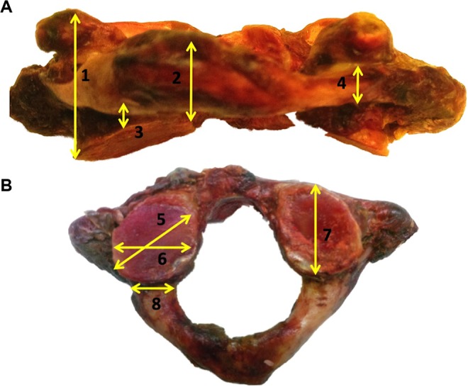
Coronal (A) and axial (B) images of representative cadaveric C1 vertebra. Anatomic measurements included (1) lateral mass (LM) height (maximum), (2) LM height (minimum) (3) inferior pedicle to inferior LM, (4) pedicle height, (5) LM width (maximum), (6) LM width (minimum), (7) LM depth, and (8) pedicle width.
Figure 2.
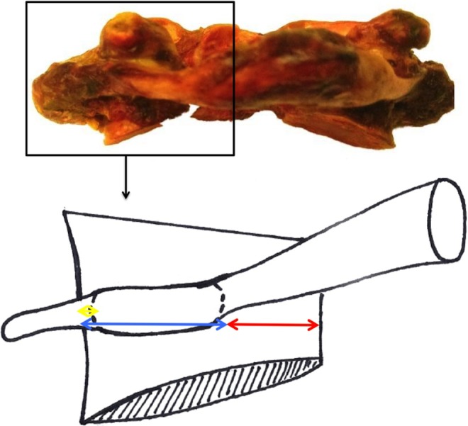
Schematic representation of anatomic relationships between C1’s pedicle and lateral mass (LM). Medial pedicle to medial LM (red), medial pedicle to lateral LM (blue), and lateral pedicle to lateral LM (yellow).
Figure 3.
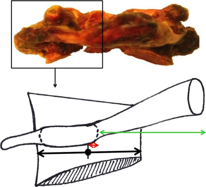
Anatomic landmarks relative to C1 pedicle’s medial border. Midline to medial pedicle (green) and center of lateral mass (LM) (“Start-Point”) to medial pedicle (red).
With these measurements, the following 2 calculations were performed:
Percentage of the C1 LM medial to the medial border of the C1 pedicle = (Distance from the medial border of the C1 pedicle to the medial aspect of the LM) / (Width of the LM) (Figure 2).
Distance from the LM’s center (screw “start-point”) to the medial aspect of the C1 pedicle = (LM width / 2) – (distance from the medial border of the C1 pedicle to the medial border of the C1 LM) (Figure 3).
Results
Forty-two C1 LMs (21 vertebrae) were analyzed. Measurements of the LM and pedicle dimensions are presented in Table 1. The average pedicle width was approximately 4 mm wider than its height. The pedicle’s height was on average 5.0 mm; it was as thin as 2.9 mm and no greater than 8 mm. The LM width varied from 11.6 to 20.2 mm. The depth of LM ranged from 14.7 to 21.4 mm. The height of the LM varied from as small as 4.4 mm at its smallest point to as much as 28.3 mm at its largest point. There was on average 3.5 ± 0.6 mm of the LM inferior to the inferior aspect of the pedicle.
Table 1.
Dimensions of C1 Lateral Masses and Pedicles.
| Distance, mm, Mean ± SD (Range) | |
|---|---|
| C1 lateral mass (LM) | |
| Width (minimum) | 14.7 ± 1.6 (11.6-18.4) |
| Width (maximum) | 17.0 ± 1.6 (14.2-20.2) |
| Height (minimum) | 6.3 ± 1.1 (4.4-9.0) |
| Height (maximum) | 20.6 ± 2.4 (17.7-28.3) |
| Depth | 17.2 ± 1.6 (14.7-21.4) |
| C1 pedicle | |
| Width | 9.0 ± 1.1 (6.8-13.1) |
| Height | 5.0 ± 1.1 (2.9-7.9) |
| Inferior pedicle to inferior LM | 3.5 ± 0.6 (2.2-4.7) |
The relationships between the C1 pedicle and LM borders are presented in Table 2 and Figure 2. The lateral aspect of the C1 pedicle was nearly confluent with the LM. There was 6.9 ± 1.5 mm of bone medial to the medial C1 pedicle, which constituted 41% ± 9% of the LM width.
Table 2.
Anatomic Relationship Between C1 Pedicle and C1 Lateral Mass (LM).
| Pedicle Relative to LM | Distance, mm, Mean ± SD (Range) |
|---|---|
| Medial pedicle to medial LM | 6.9 ± 1.5 (3.3-11.3) |
| % of LM | 41 ± 9 (22-67) |
| Medial pedicle to lateral LM | 10.1 ± 1.9 (5.3-13.0) |
| % of LM | 59 ± 9 (33-78) |
| Lateral pedicle to lateral LM | 1.3 ± 1.9 (−3.9 to 4.5) |
Measurements of anatomic landmarks relative to C1’s medial pedicle are presented in Table 3 and Figure 3. The center of the LM (“screw starting point”) was 1.6 ± 1.5 mm lateral to the medial pedicle. Since the medial pedicle was 13.5 mm from the midline of the C1 lamina, the “screw starting point” can be found approximately 15 mm from the midline on the LM.
Table 3.
Anatomic Landmarks Relative to the C1 Pedicle’s Medial Border.
| Distance, mm, Mean ± SD (Range) | |
|---|---|
| Medial pedicle to center of vertebra | 13.5 ± 2.0 (10.2-17.5) |
| Center of lateral mass (“start-point”) to medial Pedicle | 1.6 ± 1.5 (−4.3 to 2.7) |
Discussion
Instrumentation of the C1 LM provides the foundation for atlantoaxial fixation. Identification of the correct starting point for C1 LM screws is critical for achieving safe C1 LM fixation. A medially placed screw has the potential to damage the spinal cord or even the vertebral artery as the artery can course on the medial aspect of the LM, while a laterally placed screw can injure the vertebral artery as it courses lateral to the LM. In a series of 390 C1 LM screws in 196 patients, Hu et al22 noted 10 cases in which there was partial entry of the vertebral artery laterally and 7 separate screws that were medial in the spinal canal, of which 2 required revision. Bransford et al23 also demonstrated that 6% (11/216) of C1 LM screws were misplaced; many of these screws appeared to be the result of an incorrect start point and/or poor screw angulation.22
Traditionally, the proper starting point for a C1 LM screw is the center of the LM. Since the borders of the C1 LM may be difficult to visualize secondary to the C2 nerve and vascular plexus, we have proposed using the C1 pedicle as an additional guide to determine the center of the LM. Using this technique, there is no need to dissect the entire C2 nerve root, and dissect through the vascular plexus. Instead, the surgeon needs to only identify the medial wall of the C1 pedicle. The medial pedicle is easy to palpate with a nerve hook intraoperatively as it is the extension of the C1 arch into the LM. In this study, we found that the C1 pedicle is almost confluent with the lateral wall of the LM and that the medial aspect of the C1 pedicle is a reliable reference point for locating the center of the C1 LM. The center of the LM is 1.6 ± 1.5 mm lateral to the medial pedicle wall. Approximately 40% of the LM is medial to the medial pedicle wall.
While several authors have described using the posterior C1 arch to guide placement of an LM screw, this is the first study to quantify the relationship of the C1 pedicle to the center of the LM. Blagg et al24 stated that the safest entry point of the C1 LM was directly beneath the medial edge of the posterior arch/lamina where it joins the LM. On the contrary, other authors have recommended the ideal starting point to be at the insertion of the inferior posterior C1 arch at the midpoint of the C1 LM.14 Simsek et al14 and Hong et al15 found that the average distances between the midline of the C1 lamina and the middle of the C1 LM were 18.66 ± 1.6 and 17.6 ± 1.2 mm, respectively. They also reported that the average distances between the midline of the C1 lamina and the medial wall of the C1 pedicle were 14.06 ± 1.3 mm14 and 14.2 ± 1.2 mm,15 respectively. Subtracting these averages suggests that the centers of the C1 LM were on average 4.6 mm14 and 3.4 mm15 lateral to the medial pedicle. Our study found that the center of the LM is 1.5 mm lateral to the medial pedicle. These calculations and our direct measurements suggest that the medial border of the pedicle may be too medial of a starting point while the insertion point of the C1 arch onto the C1 LM is too lateral of a starting point.
The location of the medial wall of the C1 pedicle in our study was found on average 13.49 ± 1.95 mm from the C1 lamina’s midline which is in general in agreement with other anatomical studies.14,15 This measurement was used to determine that the amount of LM medial to the medial pedicle was 41%. This reinforces the fact that the C1 pedicle footprint sits on the lateral aspect of the LM with a significant amount of LM bone medial to the medial pedicle.
Our study found that the average minimum and maximum LM widths were 14.74 and 17.02 mm, respectively These dimensions are consistent with the average published LM’s overall width (12.32-17.52 mm)14,25–28 and distance between the medial wall and center of the LM (7.3 ± 1.3 mm).29
The cranial-caudal dimensions of the LM also dictate safe and accurate C1 LM screw fixation. A minimum height of 4 mm in the LM best permits accurate C1 LM screw placement. As the average LM height below the laminar arch at the level of the LM’s center is often less than 4 mm,14,15,29,30 removal of the inferior aspect of the dorsal arch is often required for proper screw placement by avoiding C1-2 facet joint violation. However, overaggressive removal of the inferior dorsal arch into the pedicle analogue may put the vertebral artery at risk, as this area has considerable anatomic variation (up to 19.2% have been reported to be less than 4.0 mm in height).27,30,31 In our study, the average height for C1 LM below the dorsal arch was 3.47 mm, which is slightly less than the literature’s reported averages.14,15,29,30 Nevertheless, our average LM height (6.3-20.6 mm), LM depth (17.19 mm), pedicle width (9.04 mm), and pedicle height (5.00 mm) are consistent with respective dimensions in previous studies of different ethnic cadaveric atlas specimens,14,15,25,27–30 which suggest that our quantifications of the anatomic relationships between the C1 pedicle and the center of the C1 LM are widely reliable and applicable.
It is important to recognize that the C1 ring is a unique structure, and this begins with its embryology. C1 ossification most often occurs in 2 sites from each LM. The ossification then continues into the anterior arch, and not infrequently, an additional ossification site is found in the anterior arch. Once this is completed, the posterior arch ossifies, but there can be a failure of complete posterior arch formation in up to 6% of the population.32 Furthermore, some would argue that the bone connecting the posterior arch with the C1 LM is not a true pedicle, but for ease of understanding, this section of bone was referred to as a pedicle throughout this article.
Limitations of our study include a small sample of cadaveric specimens with little ethnic variation. It is also a direct anatomic evaluation of cadaveric specimens without clinical or radiographic correlation. Additionally, this study only demonstrates the safety of the proposed starting point, it does not compare the accuracy to the traditional starting point. Future studies should focus on application of this technique in the clinical setting with documenting accuracy of C1 LM screw placement using postoperative computed tomography imaging. Furthermore, the relationship between the medial border of the pedicle and the medial border of the LM was evaluated with cadaveric measurements, but not by advanced imaging. Future work confirming this on advanced imaging studies would be beneficial. Finally, because of significant variation in C1 anatomy, surgeons should not rely on this measurement alone, rather they should confirm the relationship between the medial border of the LM and the medial border of the pedicle on preoperative imaging.
Conclusion
The location of the center of the C1 LM (screw “start-point”) is 1.6 mm lateral to the medial wall of the C1 pedicle. There is 6.9 ± 1.5 mm of bone medial to the medial C1 pedicle, which constitutes 41% ± 9% of the LM width. Understanding this anatomical relationship may obviate the need to define the entire LM’s medial-lateral dimension, avoid sacrificing the C2 nerve root, and minimize mobilization of the venous plexus.
Footnotes
Declaration of Conflicting Interests: The author(s) declared no potential conflicts of interest with respect to the research, authorship, and/or publication of this article.
Funding: The author(s) received no financial support for the research, authorship, and/or publication of this article.
References
- 1. Brooks AL, Jenkins EB. Atlanto-axial arthrodesis by the wedge compression method. J Bone Joint Surg Am. 1978;60:279–284. [PubMed] [Google Scholar]
- 2. Gallie WE. Fractures and dislocations of cervical spine. Am J Surg. 1939;46:495–499. [Google Scholar]
- 3. Holness R, Huestis W, Howes W, Langille R. Posterior stabilization with an interlaminar clamp in cervical injuries: technical note and review of the long term experience with the method. Neurosurgery. 1984;14:318–322. [DOI] [PubMed] [Google Scholar]
- 4. Jeanneret B, Magerl F. Primary posterior fusion C1/2 in odontoid fractures: indications, technique, and results of transarticular screw fixation. J Spinal Disord. 1992;5:464–475. doi:10.1097/00002517-199212000-00012. [DOI] [PubMed] [Google Scholar]
- 5. Du J, Aichmair A, Kueper J, Wright T, Lebl D. Biomechanical analysis of screw constructs for atlantoaxial fixation in cadavers: a systematic review and meta-analysis. J Neurosurg Spine. 2015;22:151–161. [DOI] [PubMed] [Google Scholar]
- 6. Madawi AA, Casey AT, Solanki GA, Tuite G, Veres R, Crockard HA. Radiological and anatomical evaluation of the atlantoaxial transarticular screw fixation technique. J Neurosurg. 1997;86:961–968. doi:10.3171/jns.1997.86.6.0961. [DOI] [PubMed] [Google Scholar]
- 7. Resnick DK, Benzel EC. C1-C2 pedicle screw fixation with rigid cantilever beam construct: case report and technical note. Neurosurgery. 2002;50:426–428. doi:10.1097/00006123-200202000-00039. [DOI] [PubMed] [Google Scholar]
- 8. Goel A, Laheri V. Plate and screw fixation for atlanto-axial subluxation. Acta Neurochir (Wien). 1994;129:47–53. doi:10.1007/BF01400872. [DOI] [PubMed] [Google Scholar]
- 9. Harms J, Melcher RP. Posterior C1-C2 fusion with polyaxial screw and rod fixation. Spine (Phila Pa 1976). 2001;26:2467–2471. doi:10.1097/00007632-200111150-00014. [DOI] [PubMed] [Google Scholar]
- 10. Bransford RJ, Russo AJ, Freeborn M, et al. Posterior C2 instrumentation: accuracy and complications associated with four techniques. Spine (Phila Pa 1976). 2011;36:E936–E943. doi:10.1097/BRS.0b013e3181fdaf06. [DOI] [PubMed] [Google Scholar]
- 11. Parker SL, McGirt MJ, Garcés-Ambrossi GL, et al. Translaminar versus pedicle screw fixation of C2: comparison of surgical morbidity and accuracy of 313 consecutive screws. Neurosurgery. 2009;64(5 suppl 2):343–348. doi:10.1227/01.NEU.0000338955.36649.4F. [DOI] [PubMed] [Google Scholar]
- 12. Payer M, Luzi M, Tessitore E. Posterior atlanto-axial fixation with polyaxial C1 lateral mass screws and C2 pars screws. Acta Neurochir (Wien). 2009;151:223–229. doi:10.1007/s00701-009-0198-4. [DOI] [PubMed] [Google Scholar]
- 13. Mummaneni PV, Lu DC, Dhall SS, Mummaneni VP, Chou D. C1 lateral mass fixation: a comparison of constructs. Neurosurgery. 2010;66(3 suppl):153–160. doi:10.1227/01.NEU.0000365804.75511.E2. [DOI] [PubMed] [Google Scholar]
- 14. Simsek S, Yigitkanli K, Seçkin H, et al. Ideal screw entry point and projection angles for posterior lateral mass fixation of the atlas: an anatomical study. Eur Spine J. 2009;18:1321–1325. doi:10.1007/s00586-009-1105-7. [DOI] [PMC free article] [PubMed] [Google Scholar]
- 15. Hong X, Dong Y, Yunbing C, Qingshui Y, Shizheng Z, Jingfa L. Posterior screw placement on the lateral mass of atlas: an anatomic study. Spine (Phila Pa 1976). 2004;29:500–503. doi:10.1097/01.BRS.0000113874.82587.33. [DOI] [PubMed] [Google Scholar]
- 16. Dewan MC, Godil SS, Mendenhall SK, Devin CJ, McGirt MJ. C2 nerve root transection during C1 lateral mass screw fixation: does it affect functionality and quality of life? Neurosurgery. 2014;74:475–480. doi:10.1227/NEU.0000000000000306. [DOI] [PubMed] [Google Scholar]
- 17. Kang MM, Anderer EG, Elliott RE, Kalhorn SP, Frempong-Boadu A. C2 nerve root sectioning in posterior C1-2 instrumented fusions. World Neurosurg. 2012;78:170–177. doi:10.1016/j.wneu.2011.07.010. [DOI] [PubMed] [Google Scholar]
- 18. Elliott RE, Kang MM, Smith ML, Frempong-Boadu A. C2 nerve root sectioning in posterior atlantoaxial instrumented fusions: a structured review of literature. World Neurosurg. 2012;78:697–708. doi:10.1016/j.wneu.2011.10.035. [DOI] [PubMed] [Google Scholar]
- 19. Squires J, Molinari RW. C1 lateral mass screw placement with intentional sacrifice of the C2 ganglion: functional outcomes and morbidity in elderly patients. Eur Spine J. 2010;19:1318–1324. doi:10.1007/s00586-010-1452-4. [DOI] [PMC free article] [PubMed] [Google Scholar]
- 20. Yeom JS, Kafle D, Nguyen NQ, et al. Routine insertion of the lateral mass screw via the posterior arch for C1 fixation: feasibility and related complications. Spine J. 2012;12:476–483. doi:10.1016/j.spinee.2012.06.010. [DOI] [PubMed] [Google Scholar]
- 21. Young JP, Young PH, Ackermann MJ, Anderson PA, Riew KD. The ponticulus posticus: implications for screw insertion into the first cervical lateral mass. J Bone Joint Surg Am. 2005;87:2495–2498. doi:10.2106/JBJS.E.00184. [DOI] [PubMed] [Google Scholar]
- 22. Hu Y, Kepler C, Albert T, et al. Accuracy and complications associated with the freehand C-1 lateral mass screw fixation technique: a radiographic and clinical assessment. J Neurosurg Spine. 2013;18:372–377. [DOI] [PubMed] [Google Scholar]
- 23. Bransford RJ, Freeborn MA, Russo AJ, et al. Accuracy and complications associated with posterior C1 screw fixation techniques: a radiographic and clinical assessment. Spine J. 2012;12:231–238. doi:10.1016/j.spinee.2012.02.011. [DOI] [PubMed] [Google Scholar]
- 24. Blagg S, Don A, Robertson P. Anatomic determination of optimal entry point and direction for C1 lateral mass screw placement. Spinal Disord Tech. 2009;22:233–239. doi:10.1097/BSD.0b013e31817ff95a.Full. [DOI] [PubMed] [Google Scholar]
- 25. Schulz R, Macchiavello N, Fernández E, et al. Harms C1-C2 instrumentation technique: anatomo-surgical guide. Spine (Phila Pa 1976). 2011;36:945–950. doi:10.1097/BRS.0b013e3181e887df. [DOI] [PubMed] [Google Scholar]
- 26. Dong Y, Hong MX, Jianyi L, Lin MY. Quantitative anatomy of the lateral mass of the atlas. 2003;28:860–863. [DOI] [PubMed] [Google Scholar]
- 27. Tan M, Wang H, Wang Y, Zhang G, Yi P. Morphometric evaluation of screw fixation in atlas via posterior arch and lateral mass. 2003;28:888–895. [DOI] [PubMed] [Google Scholar]
- 28. Ma X, Yin Q, Wu Z, Xia H. Anatomic considerations for the pedicle screw placement in the first cervical vertebra. 2005;30:1519–1523. [DOI] [PubMed] [Google Scholar]
- 29. Wang MY, Samudrala S. Cadaveric morphometric analysis for atlantal lateral mass screw placement. Neurosurgery. 2004;54:1436–1440. doi:10.1227/01.NEU.0000124753.74864.07. [DOI] [PubMed] [Google Scholar]
- 30. Christensen DM, Eastlack RK, Lynch JJ, Yaszemski MJ, Currier BL. C1 anatomy and dimensions relative to lateral mass screw placement. 2007;32:844–848. [DOI] [PubMed] [Google Scholar]
- 31. Ebraheim N, Xu R, Ahmad M, Heck B. The quantitative anatomy of the vertebral artery groove of the atlas and its relation to the posterior atlantoaxial approach. Spine (Phila Pa 1976). 1998;23:320–323. [DOI] [PubMed] [Google Scholar]
- 32. Junewick JJ, Chin MS, Meesa IR, Ghori S, Boynton SJ, Luttenton CR. Ossification patterns of the atlas vertebra. AJR Am J Roentgenol. 2011;197:1229–1234. [DOI] [PubMed] [Google Scholar]