

Abstract
Robot-assisted minimally invasive surgical systems enable procedures with reduced pain, recovery time, and scarring compared to traditional surgery. While these improvements benefit a large number of patients, safe access to diseased sites is not always possible for specialized patient groups, including pediatric patients, due to their anatomical differences. We propose a patient-specific design paradigm that leverages the surgeon’s expertise to design and fabricate robots based on preoperative medical images. The components of the patient-specific robot design process are a virtual reality design interface enabling the surgeon to design patient-specific tools, 3-D printing of these tools with a biodegradable polyester, and an actuation and control system for deployment. The designed robot is a concentric tube robot, a type of continuum robot constructed from precurved, elastic, nesting tubes. We demonstrate the overall patient-specific design workflow, from preoperative images to physical implementation, for an example clinical scenario: nonlinear renal access to a pediatric kidney. We also measure the system’s behavior as it is deployed through real and artificial tissue. System integration and successful benchtop experiments in ex vivo liver and in a phantom patient model demonstrate the feasibility of using a patient-specific design workflow to plan, fabricate, and deploy personalized, flexible continuum robots.
Keywords: Continuum robots, personalized surgical robots, 3D printing, minimally invasive procedures
Introduction
ROBOT-assisted minimally invasive surgical systems offer a number of advantages, but there remain certain limitations of current commercial systems. First, their overall large size and high cost limit the feasible use cases. Second, there are situations where access via a straight path using rigid tools may pose a safety risk. Finally, in order to accommodate a large range of patients for a wide variety of procedures, the systems are built to be highly general. This model may succeed at helping a large portion of the population, but it tends to marginalize specialized patient populations with non-standard anatomical features.
Pediatric patients are one such specialized group, whose compact anatomy often leads to higher risks. For example, access to the kidney is relatively straightforward in adults using a straight needle. However, the smaller body surface area of pediatric patients makes it more difficult to gain access to diseased sites due to intervening tissues. Safe access to the kidney is critical for treatment of tumors, which can form in the kidney and often spread to other regions of the body. These childhood renal tumors account for approximately 7% of all childhood cancers4. The current standard for surgical treatment is a procedure called nephrectomy, where the kidney (or part of the kidney) is removed. There have also been studies showing the effectiveness of percutaneous radiofrequency ablation (RFA)22 as a surgical treatment. The development of a tool that could allow for percutaneous entry below the 12th rib followed by a nonlinear path through the renal pelvis and curving towards the diseased region of the kidney could improve safe access and avoid injury to the lung and pleura i.e., pneumothorax, hemothorax, hydrothorax.
Although this work focuses on access to the pediatric kidney, we propose the personalized design workflow as a general platform that can be applied to other procedures and populations. The work presented here can therefore be viewed as a case study for a sample group and application. The overall goal is to bring the necessary components together to demonstrate the feasibility of integration and implementation of a patient-specific robotic system.
Concentric Tube Robots
We propose to use a class of continuum robots known as concentric tube robots24,29. Concentric tube robots consist of nesting, precurved tubes that are each made with an elastic material and fit concentrically one inside the next. As the tubes are inserted and rotated with respect to each other, their elastic interaction causes the shape of the overall robot to bend and twist.
Applications of concentric tube robots include steerable needles and teleoperated manipulators12. Previous work has considered the use of concentric tube robots for a variety of surgical procedures, including trans-endoscopic2,31, transvascular3,14, percutaneous7,15,24, and natural orifice6,26 procedures. While it is useful to ground initial research in a specific procedure, it is also important to address the potential of such robots in a wider context. There have been initial proposals for customized concentric tube robots6,8 but no previous development of a generalized workflow.
Previous Concentric Tube Robot Design Approaches
Over the past decade, researchers have developed a number of methods and tools for designing concentric tube robots. Burgner et al.5,6 used an optimization algorithm to find a design that covered the target surgical workspace, emphasizing the importance of reachability over a given volume. Bergeles et al.3 divided a intracardiac design problem into two parts: design of the portion of the concentric tube robot responsible for navigation to the surgical site and design of the portion responsible for performance of the surgical task. Torres et al.28 incorporated motion planning and a robot’s time-varying shape to create a robot that can reach multiple clinically relevant sites while avoiding obstacles.
Application-specific customization typically requires optimization of a selected objective function. In contrast, we propose a method that enables a surgeon to design concentric tube robots based on his or her expertise, rather than relying solely on the ability to formalize and weight a combination of desired requirements and constraints. Although any of the previously described methods could be used for designing the concentric tubes, we have selected to build on our approach developed previously19, which places the surgeon in the design loop.
Previous Fabrication Approaches
Concentric tube robots to date have primarily been fabricated from Nitinol, a superelastic alloy. Concentric tube robot designs leverage the high recoverable strains of Nitinol, which are generally 8-11%30. The standard method for creating concentric tubes includes creating a fixture of the desired shape, bending a Nitinol tube into that fixture, and shape-setting the tube through heating-cooling cycles or heating it to an extremely high temperature13. After the tubes are shape-set, the curvatures can relax, making it difficult to achieve the desired design.
Our patient-specific design paradigm prompted a complementary fabrication process. We proposed 3-D printing because it enables rapid fabrication of a physical model from a digital model21. To find materials appropriate for making concentric tubes that withstand high strains during bending, we performed an initial investigation of numerous 3-D printing methods21, including Fused Deposition Modeling (FDM), Digital Light Processing (DLP), Selective Laser Sintering (SLS), Stereolithography (SLA), and Multi-jet Printing (MJP). Despite this thorough investigation of available materials, there was not a material that clearly fit all the needs for fabricating concentric tube robots.
Contributions
The primary contribution of this paper is to establish the feasibility of a patient-specific design workflow from preoperative images to physical implementation of a continuum surgical robot, while putting the surgeon in the design loop. We present two main studies: In Study 1 we measure the forces during insertion of a 3-D printed concentric tube robot through artificial and ex vivo tissue and validate the ability of the robot and the proposed actuation system20 to perform these insertions. In Study 2 we demonstrate, from start to finish, the patient-specific design process and evaluate benchtop experimental data from deploying the system in a phantom patient model. In addition to these studies, we build upon our previous work19,20,21, which initially demonstrated individual components of our proposed patient-specific design workflow. Here we present improvements to and analysis of each step in the workflow, with the most significant changes being: analysis of surgeon activity during the design process using a virtual reality interface, identification and validation of a new 3-D printing material for fabricating concentric tubes, and fabrication and teleoperation of surgeon-designed instruments.
Materials and Methods
Design: Virtual Reality Design Interface
Here we describe an interface that immerses a surgeon in a 3D virtual environment in order to facilitate design of a patient- and procedure-specific concentric tube robot.
Physical Setup and Design Process
The design interface (Figure 2) consists of the following: An Oculus Rift Development Kit 2 (DK2; Oculus VR) is a virtual reality head-mounted display that enables 3D rendering of the patient anatomy and concentric tube robot designs. A PHANTOM Omni (SensAble Technologies, Inc.) is a haptic device that allows bidirectional interactions between the surgeon and the interface. A set of da Vinci surgical system foot pedals (Intuitive Surgical, Inc.) are used to switch between the various modes of the system as shown in Figure 2(c). These components are integrated using Chai3D (www.chai3d.org), an open source framework for haptics, visualization, and real-time simulation.
Fig. 2.
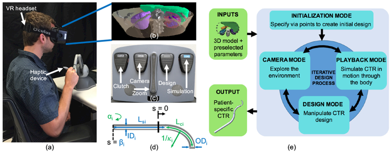
The surgeon design interface includes (a) virtual reality headset and six degree-of-freedom haptic device. The headset is used to render (b) a 3D model of the relevant patient anatomy, (c) Foot pedals are used to switch between the different interaction modes of the interface, (d) Concentric tube robot parameters shown in blue are preselected and include the number of tubes (n), outer and inner diameters (ODi, IDi), straight length (Lsi), and translation actuator distance (βi). Concentric tube robot parameters shown in green can be modified with the design interface and include individual tube curvature (κi,), curved length (Lci), rotation actuator angle (αi), and Young’s Modulus (Ei). (e) Iterative workflow for the surgeon design interface. Inputs to the interface include the reconstructed model of the patient anatomy and surgeon-defined tube parameters, and the output is a set of patient-specific concentric tube parameters.
The patient model shown in Figure 2(b) is developed based on a specific patient’s preoperative medical images (here, computerized tomography, or CT, scans). The images are segmented, and a 3D model of each organ in the area of interest is reconstructed and imported into the virtual environment (prior work19 provides more detail). We then set the values of a few tube parameters based on the specific patient and procedure. Figure 2(d) shows a high number of tunable concentric tube parameters; this creates a large overall design space, which is reduced into a more reasonable space using the expertise of the surgeon. For any given tube i (where i = 0 to i = n − 1), the parameters shown in green in Figure 2(d) (κi, Lci, αi as well as Ei (Young’s modulus) are adjustable, and the total number of tubes (n), along with the parameters shown in blue {ODi, IDi, Lsi, βi), are determined by the surgeon. It should be noted that αi (rotation actuator angle) and βi (translation actuator distance) are configuration-dependent parameters. Based on the obstacles that must be avoided in order to reach the target location within the body, the surgeon can approximate the number of distinct curves the path will need to take, and therefore the number of tubes (n).The size of the patient places an upper limit on the maximum diameter of the concentric tube set (ODn−1), and the size of the tool to be passed through the concentric tube robot will determine the minimum possible inner diameter of the smallest tube (ID0). The remaining ODi and IDi can be determined using the limits on these two extremes along with the limitations on minimum wall thickness. Although set here by the surgeon, future versions of the interface could include these preselected parameters as adjustable parameters.
The process of designing a set of concentric tubes is iterative (Figure 2(e)). The interface organizes the main tasks into four “modes” (Initialization Mode, Design Mode, Camera Mode, Simulation Mode). The following descriptions and examples are for a three-tube (n = 3) concentric tube robot.
Initialization Mode:
An initial design is generated using a combination of the surgeon’s expertise along with automatic computation of the kinematics. The surgeon selects n + 1 via points through which the robot will ideally pass and orients a vector representing the straight portion of the concentric tube robot as shown in Figure 3(a). A piecewise, constant-curvature spline (Figure 3(b)) is fit through the via points as explained in detail in previous work19. Each radius of curvature represents the radius of curvature of a section of the backbone of the overall concentric tube set and is used to back-calculate the individual tube parameters. Each curved section consists of i + 1 overlapping tubes with an equilibrium curvature for the planar case given by
| (1) |
where Ii and Ei are the cross-sectional moment of inertia and Young’s modulus of tube i, respectively29,30, and m is the number of overlapping tubes. Equation 1 is then rearranged and solved to find each κi. Finally, we assume that each constant curvature spline segment consists of overlapping curved tube sections, and therefore determine the values of Lci by adding the length of the corresponding spline segment to the lengths of any previous segments. After computing the actuator angles (αi) and distances (βi) of each tube19, the initial tube parameters are used to compute the deployed concentric tube robot configuration, using previously developed mechanics models9,23. Procrustes analysis is used to rotate the computed concentric tube robot configuration (shown in green in Figure 3(c)) about (treated as the origin) in order to align it with the initial via points25, giving the configuration shown in blue in Figure 3(c). The final configuration is displayed in the surgeon design interface as shown in Figure 3(d). The methods and constraints used during this initialization process were selected to simplify the initial design generation, because a sequence of via points on its own creates a very large design space. Alternative design optimization algorithms and parameter initialization methods could easily be integrated into the interface.
Fig. 3.
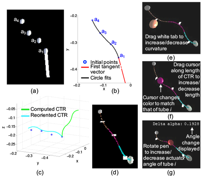
Initialization of a concentric tube robot design includes (a) using the interface to place via points through which the robot will ideally pass, (b) fitting a piecewise, constant-curvature spline to the via points, (c) computing the forward kinematics of the robot and aligning the configuration with the via points, and (d) displaying in the interface the initial design to the surgeon. Interactions with the virtual concentric tube robot can change the (e) curvature, (f) curved length, and (g) actuator angle of any of the tubes.
Design Mode:
The surgeon can change several tube parameters once the initial design has been generated. As shown in Figure 3(e-g), the surgeon can alter the curvature, curved length, and actuator angle of each tube. Different materials can also be selected and used in the design process. However, in this work we focus on a single 3-D printable material, as explained in subsequent sections. Various interactions are performed by moving the Omni and pressing a combination of its two buttons when the cursor is in contact with the robot body, the proximal or distal spheres located at either end of the robot, or the white tab (perpendicular to the tangent of the curve at the midpoint). Once the desired tube parameter has been changed, the forward kinematics are computed, and the new configuration is drawn. Future versions of this interface could include additional design constraints that may not be intuitive to the surgeon operator, in order to ensure elastic stability and minimize torsion of the final design.3,16,32
Camera Mode:
One of the motivations for using a virtual reality head-mounted display is to enable intuitive viewing and exploration of the patient anatomy in 3D. 2D medical images can be difficult to interpret, especially when designing a 3D device. Camera Mode can make visualization and interpretation easier for the surgeon, especially in the region of the anatomical target. When a surgeon selects camera mode via the foot pedal (Figure 2(c)), a semi-transparent sphere can be manipulated to orient the anatomy with respect to the viewpoint, and foot pedals can be used to zoom. The surgeon can also select from preset sagittal, coronal, and transverse views.
Simulation Mode:
It is important for the surgeon to visualize the concentric tube robot in motion through the patient’s body. The combination of possible insertions and rotations creates a large space of potential deployment sequences. Based on the requirements of nonlinear renal access and the need to minimize lateral movement and forces, we have limited the simulation to an approximate follow-the-leader deployment sequence9,11, where the backbone follows the path through space traced by the tip. The sequence is considered approximate because, as outlined in11, constant curvature tubes can only follow the leader exactly when all tube curvatures lie in the same plane, which is not currently constrained in the design process. The goal here is to enable design and teleoperation of a surgeon-created tool that can reach a target, avoid obstacles, and avoid tissue damage due to excessive lateral movement. We use this deployment sequence to compute and display the configuration of the concentric tube robot as the insertion distance (βi) increases. The surgeon can pause and restart the simulation at any point, in order to better analyze the robot’s position relative to the anatomy.
From Virtual Design to Fabricable Digital Model
Once the surgeon has decided on a final set of concentric tubes, the tubes must be fabricated. In order to do so, the final physical parameters, including ODi IDi, Lci, Lsi, and κi, are written to a text file. We have a template CAD model of an individual tube, which can be used to quickly generate a 3-D model with these specific parameter values. This is accomplished by importing the tube parameter file as a design table, which is a Solidworks (Dassault Systèmes) feature that enables building multiple configurations of parts by specifying parameters in an embedded Microsoft Excel worksheet. After this import, the template model is automatically updated to match the specific tube parameter values found in the design table. The resulting model is then saved as an STL file for fabrication as explained in the subsequent section.
Fabrication: Concentric Tubes and Actuation System
For a given procedure, two main components must be fabricated – the concentric tubes and the actuation system. After the surgeon has designed the concentric tube robot, the tubes are 3-D printed based on this patient-specific design. The actuation system is not fully fabricated for an individual patient, but is modular, such that the appropriate number of actuation modules can be selected and assembled for the particular procedure20.
3-D Printing Concentric Tubes
A number of key factors must be considered when evaluating materials and 3-D printing methods. First, some methods require the use of a support material in order to fabricate hollow, curved tubes. If the support material is not easily dissolvable, it has to be manually removed from the inside of the tubes, which can break during cleaning. Second, the quality of surface finishes depends on the material and printing method. Some methods produce parts with a rough, powdery surface that require labor intensive post-processing. The surfaces must be smooth for low-friction insertion and rotation of nested tubes. Third, the material must be biocompatible.
We evaluated materials beyond those previously tested21, several of which are shown in Table I. The main issues encountered with both thermoplastic polyurethanes were the extremely low values of Young’s Modulus, which caused buckling, and the difficulty in printing thin-walled structures. In comparison, the value of Young’s Modulus of Polycaprolactone (PCL) was significantly higher and the material could be consistently printed in very thin layers. PCL can also be printed without any support material and with a smooth surface finish on an FDM machine (Figure 4(a)). Moreover, PCL is available commercially in a form ready for 3-D printing. And unlike any of our previously tested 3-D printing materials, PCL is a biodegradable polyester that already has several uses in the medical field, such as long term implantable devices, and can be sterilized using electron beam (EB) sterilization18. For these reasons, we found PCL to be the most appropriate material for 3-D printing concentric tube robots and it was selected for the studies described here.
TABLE I.
3-D Printed Material Comparison*
| Type | Name | Strength [MPa] | Modulus [MPa] | Min. wall [mm] |
|---|---|---|---|---|
| Polycaprolactone | Makerbot flexible filament | 7.4 | 2400 | 0.4 |
| Thermoplastic Polyurethane | Semiflex | 9 | 25 | 0.8 |
| Thermoplastic Polyurethane | Ninjaflex | 4 | 12 | 0.8 |
This table can be compared to Table V21
Fig. 4.
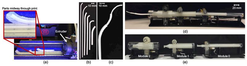
Sample tubes printed with polycaprolactone (a) during the 3-D printing process using a MakerBot Replicator 2X and shown as (b) individual tubes and (c) assembled into a three-tube concentric tube robot. Modular actuation and control system shown (d) deploying a three-tube concentric tube robot and (e) separated into individual actuation modules.
Several parameter values must be known in order to reliably print and use PCL concentric tubes (Figure 4(b)). Burgner et al.1 measured an average yield strength and average Young’s Modulus of 7.4 MPa and 2.4 GPa, respectively. PCL has a melting temperature of 60°C, and we found that a print nozzle temperature of 128°C led to the most consistent prints using a MakerBot Replicator 2×. We empirically found that the smallest feasible inner diameter was 0.8 mm, the minimum wall thickness was 0.4-0.5 mm depending on the diameter of the tube, and the minimum clearance between tubes was 0.6 mm.
To fully validate PCL for clinically viable concentric tube robots, there are a number of additional tests that should be performed. In this work, we measured the insertion forces through various tissue samples and demonstrate the ability of PCL printed tubes to withstand these forces to successfully drive through the tissues (Study 1). Future studies would include model validation similar to those presented in21, validation of the consistency of stiffness and strength values in various directions, and measurements of the ultimate strength of the printed tubes. In addition, it would be feasible to use Nitinol tubes and associated shape setting methods13 with our patient-specific design process. 3-D printing has the advantage of a rapid design cycle from conception to on-the-spot fabrication, with little expertise required. The use of higher-end 3-D printers could be explored for possible improvements in diameter size, uniformity, and surface finish.
Actuation and Control System
We deploy the resulting concentric tube robot (Figure 4(c)) using a compact, lightweight, and modular actuation and control system described previously20 and shown in Figure 4(d). Each module controls two degrees of freedom – rotation and translation – of a single tube. Rather than designing the entire actuation system for each patient, depending on the patient and procedure, the correct number and sized modules are selected and assembled (Figure 4(e)). Each module consists of a roller gear with teeth in both the axial and radial directions27. The resulting grid-like pattern enables a compact design because each roller gear can align axially and nest inside the previous one. Actuating one of the two spur gears that are oriented orthogonally to one another, either translates or rotates the roller gear. In contrast to previous work20, the spur gears were 3D printed using a higher performance material, PLA (polylactic acid), on an FDM machine. In addition, the entire system was attached to a Noga arm (Noga Technologies Ltd.) for repositioning.
Study 1: Deployment in Artificial and Ex Vivo Tissue
To be viable in a clinical setting, concentric tube robots must be capable of driving between or through tissue, since there are very few situations that would require moving only through free space. In order to assess whether the 3-D printed tubes and actuation system could withstand the necessary forces, we drove a three-tube concentric tube robot through both gelatin and biological tissue and measured the resulting forces. To our knowledge, these experiments present the first insertion-force data for concentric tube robots through tissues.
As shown in Figure 6(a), our selected clinical application involves insertion through various fat and tissue layers, as well as through the renal parenchyma of the kidney itself in order to reach the calyces of the renal pelvis. Nonlinear access is critical since straight line paths above the 12th rib risk puncturing the pleural cavity, and straight line paths below the 12th rib require steep angles that can result in high torques and sheering of the kidney. The tissues selected for the following experiments are representative of tissues that would be encountered during nonlinear renal access.
Fig. 6.
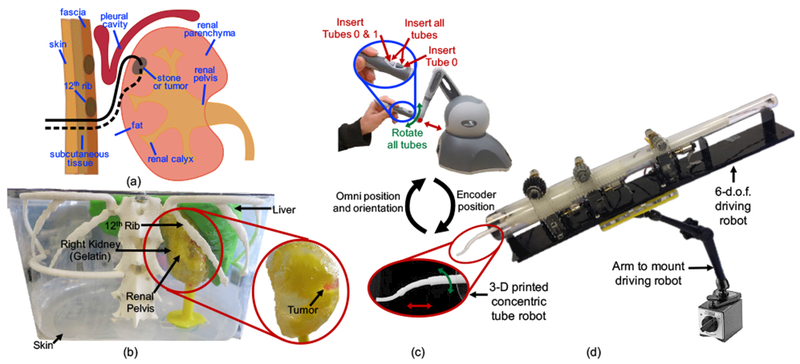
(a) Two potential concentric tube robot paths, entering under the 12th rib and snaking up into the kidney to the diseased site (either a stone or tumor), (b) Phantom patient model based on CT scans from a 9-year-old patient. Model was constructed from 3-D printed organs and a gelatin kidney, (c) Teleoperation scheme developed to enable movement that best approximated follow-the-leader deployment, (d) Actuation system mounted on a passive positioning arm for easy maneuverability.
We created a setup (Figure 5) consisting of an acrylic platform mounted on top of an ATI Industrial Automation Mini 45 force/torque sensor (resolution of 0.125 N and 0.00133 Nm). The tissue was placed on top of the platform and secured by fixing it with an acrylic top plate. The entire setup was then clamped to the table to eliminate movement of the tissue during insertion. This setup was designed to enable measurement of forces along all three axes during the insertion of any combination of the tubes.
Fig. 5.
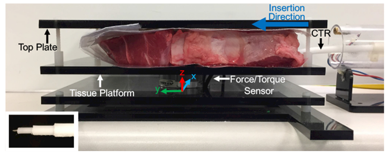
Experimental setup for measuring the forces resulting from driving a three-tube concentric tube robot through various tissues. Inset image shows tip of the concentric tube robot with attached sharp needle tip added to enable easy tissue penetration.
We fabricated two sets of concentric tube robots, consisting of three tubes each. The first set consisted solely of straight tubes, while the second set consisted of tubes with a straight segment and a constant curvature segment, selected based on curvature ranges used in previous research9,10. The parameters for the second set are given in Table II, and the straight set was printed with the same diameter values. A sharp needle tip was attached to the innermost tube in order to enable easy tissue penetration (inset image of Figure 5). For each test, the distal end (tips) of the three tubes were initially aligned, the proximal end (base) of the tubes were attached to the actuation system, and an initial tissue puncture was made with the three tubes together. A series of three constant velocity insertions, 10 mm each, were then performed to approximate follow-the-leader deployment as follows: (1) all three tubes were inserted simultaneously, (2) the outermost tube was held constant while the inner pair of tubes was inserted simultaneously, and (3) only the innermost tube was inserted. During each test, the insertion forces along all three axes and the position of the tubes were recorded.
TABLE II.
Concentric Tube Parameters
| Tube # | OD [mm] | ID [mm] | Lc [mm] | Ls | κ [mm−1] |
|---|---|---|---|---|---|
| 0 | 2.4 | 1.0 | 30 | 210 | 0.025 |
| 1 | 3.8 | 3.0 | 70 | 95 | 0.0067 |
| 2 | 5.4 | 4.4 | 40 | 40 | 0.004 |
Study 2: Patient-Specific Design and Deployment Demonstration
We demonstrate our platform technology by asking a pediatric urologic surgeon to design a concentric tube robot to access a hard-to-reach, upper-pole tumor in the kidney. The phantom patient model used was based on a 3-D reconstruction of CT scans from a 9-year-old patient. The relevant patient-specific organs, including the liver, internal structures of the kidney, and the spine and ribs, were 3-D printed with PLA (polylactic acid). The kidney was formed by pouring gelatin into a mold surrounding the 3-D printed model of the internal structures. A piece of clear LDPE (0.05 mm thick) was used for the skin in order to better visualize when the concentric tube robot was inside versus outside the phantom patient body.
The actuation system was attached to a Noga arm (Noga Technologies Ltd.) as shown in Figure 6(d). Use of the passive arm facilitated easy setup of the actuation system with respect to the phantom patient model. The surgeon then used the Omni to teleoperate the concentric tubes to reach the tumor. There are a number of possible teleoperation schemes that could be integrated into our system17. For our clinical application it was desirable to deploy via the follow-the-leader strategy11 as closely as possible. Therefore, the tubes were initially arranged with the desired relative rotation (αi) between the tubes as determined with the design interface. The surgeon was then given the ability to control (1) insertion of all three tubes simultaneously, (2) insertion of the inner tube pair, (3) insertion of the innermost tube, and (4) rotation of all three tubes together, as shown in Figure 6(c). Although standard follow-the-leader deployment does not involve any tube rotation, the surgeon may need this extra degree of control due to any misalignment during the initial arrangement of the tubes, as well as any error in the modeling.
The system was naturally clutched to avoid unwanted motion, and movement would only occur when the surgeon held down the appropriate button while simultaneously moving the Omni. The surgeon was also given audio cues, based on the follow-the-leader deployment sequence determined from the design interface, to signal when to transition to the next insertion phase (i.e., when to stop inserting all three tubes simultaneously and to start inserting just the innermost tube pair). The goal of these audio cues is to make the surgeon aware of the deployment plan, while still allowing him or her to deviate from the plan if needed.
Results
Study 1: Deployment in Artificial and Ex Vivo Tissue
The tests were performed using gelatin and cow liver, with the goal of measuring the resulting insertion forces. Figures 7(a) and 7(b) show the magnitude of these in-plane forces throughout the insertion sequence for the gelatin and liver, respectively. The solid lines show the mean over five trials, and the surrounding shaded regions show the standard deviations. The mean out-of-plane forces were measured to be less than 0.22 N for gelatin and less than 0.34 N for liver, indicating that out-of-plane motions were minor.
Fig. 7.
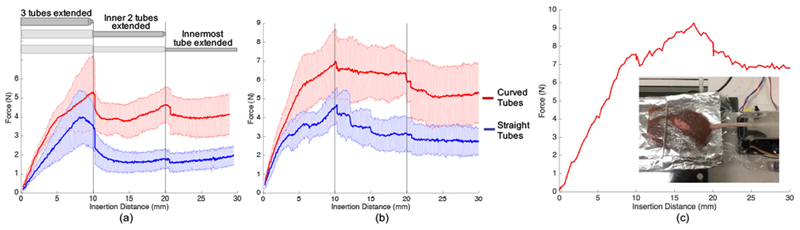
Results of Study 1. Magnitude of forces during insertion of a three-tube concentric tube robot through (a) gelatin and (b) cow liver. The approximate follow-the-leader deployment sequence is shown at the top of (a) as all three tubes were extended simultaneously to 10 mm, the inner two extended to 20 mm, and the innermost tube extended to 30 mm. (c) Peak insertion forces reached over 9 N during insertion of a concentric tube robot into the kidney, our target organ.
For both tissue samples, we see higher forces when inserting the curved tubes compared to the straight tubes. In addition, the increase in measured force is higher during the first insertion phase when all three tubes are being simultaneously inserted. There is then a distinct decrease in force at an insertion distance of 10 mm and 20 mm, corresponding to the points at which the insertion was temporarily paused before transition to the next step in the insertion sequence. This decrease is particularly apparent for the gelatin tests (Figure 7(a)), which resulted in overall less variable force data, most likely due to the more homogeneous nature of the gelatin compared to the liver. Based on additional testing, this trend of increased force during the first phase is likely due to the larger diameter of the outermost tube.
The 3-D printed tubes and modular actuation system did withstand the forces necessary to drive through both gelatin and liver. These tests also showed the ability of the 3-D printed tubes to successfully drive through inhomogeneous tissue, such as the liver. In addition, we performed a test to demonstrate the system’s ability to drive through kidney tissue, which is important for our target clinical application. As shown in Figure 7(c), the three-tube concentric tube robot could withstand over 9 N of insertion force. Due to the large degree of inhomogeneity of the kidney, we show here only a single insertion, rather than an average, since the force profiles are highly inconsistent.
Study 2: Patient-Specific Design and Deployment Demonstration
Tube Design
The 3D-reconstructed anatomical model was imported into the virtual reality-based design interface as explained in the methods. Based on the diameter of the RF ablation tool that would be passed through the concentric tube robot, the minimum inner diameter of the smallest tube was set to 1.1 mm. The remaining diameters were selected based on empirical tests performed to determine the minimum wall thickness for various sized tubes printed with PCL as well as the empirically determined minimum gap between nesting tubes. The surgeon proceeded to design two different sets of concentric tubes that each followed what he believed to be a feasible path to reach the tumor. Designing the first set of tubes took approximately 5.5 minutes, and the final configuration was a “c-shape” as shown artificially highlighted in yellow in the first column of Figure 8(a). The second set of tubes took approximately 3.5 minutes to design, and the final configuration was an “s-shape” that curved under the 12th rib (artificially highlighted in blue) and up into the kidney as shown in the second column of Figure 8(a). Based on observations of the surgeon designing these two sets of tubes and practicing using the interface prior to this, the design process varied depending on the plan the surgeon aimed to execute. Sometimes more time was spent initializing the design, and the surgeon was meticulous about examining the environment from every angle before placing each via point. Other times the surgeon was less careful about placing the initial points, and he spent the majority of the time modifying the tube parameters in later phases. An example plot of the time spent in various phases of the design process is shown in Figure 8(b). The final parameters of the designed tubes are given in Table III.
Fig. 8.
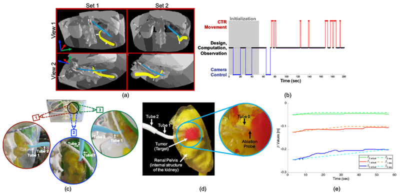
Results of Study 2. (a) Screenshots with artificially highlighted (yellow) concentric tube robot and (blue) 12th rib. The first column shows Set 1 which was designed as a “c-shape”, and the second column shows Set 2 which was designed as an “s-shape”. Two different views are given, and these views are slightly different for each set since the images are acquired from the surgeon’s view during the design process, (b) Example of time spent by a pediatric urologic surgeon in various phases throughout the design process. Phases include initialization of the design, controlling the camera, moving the concentric tube robot with respect to the anatomy, and time spent doing design, computation, and observation, (c) Three viewpoints of a surgeon-designed concentric tube robot (artificially highlighted in blue) curving below the 12th rib, into the kidney, and up to the tumor. The two outermost tubes (Tube 2 and Tube 1) are labeled in each view, and the innermost tube (Tube 0) is inside the kidney and therefore not visible, (d) Closeup view of the concentric tube robot inside the kidney with the ablation probe successfully in contact with the target tumor, (e) Insertion values (βiactual) during actual teleoperation to a target compared to planned (or desired) values βides).
TABLE III.
Example Surgeon-Designed Tube Parameters
| Tube # | OD [mm] | ID [mm] | Lc [mm] | Ls [mm] | κ [mm−1] | |
|---|---|---|---|---|---|---|
| Set 1 | 0 | 2.5 | 1.1 | 29.8 | 261.3 | 0.066 |
| 1 | 4.1 | 3.3 | 12.3 | 138.6 | 0.044 | |
| 2 | 5.9 | 4.9 | 50.0 | 50.0 | 0.035 | |
| Set 2 | 0 | 2.5 | 1.1 | 32.4 | 254.5 | 0.033 |
| 1 | 4.1 | 3.3 | 11.3 | 139.5 | 0.066 | |
| 2 | 5.9 | 4.9 | 36.9 | 50.0 | 0.034 | |
Tube Fabrication
The surgeon-designed tube sets were then 3-D printed with polycaprolactone (PCL). Printing a set of three tubes took approximately 50 minutes. The parameters of the designed tubes, including outer diameters, inner diameters, curvatures, and lengths are given in Table III. Calipers were used to measure the diameters of the tubes at several points. The outer diameters were measured to be 2.46±0.10, 3.99±0.23, and 5.87±0.33 mm for tubes 0, 1, and 2, respectively. The inner diameters were measured to be 1.0±0.08, 3.21±0.18, and 4.8±0.16 mm for tubes 0, 1, and 2, respectively.
Deployment
Before final positioning and deployment, a thin Nitinol wire (0.3 mm diameter) used as the RF ablation tool (to be replaced by an off-the-shelf ablation tool for future studies) was placed inside the innermost concentric tube such that the tips were aligned. Because this tool is over 200 times less stiff than even the innermost concentric tube, there was a negligible effect on the robots overall shape. The surgeon then used the passive positioning arm to fix the actuation system relative to the phantom model based on measurements taken during the design process, and a small puncture was made in the phantom skin layer. The surgeon then sat at the workbench next to the phantom and, using direct vision from outside the model, teleoperated each concentric tube robot (Set 1 and Set 2 described in Table III) to the target using the Omni.
The surgeon successfully reached the target, as verified visually, using both sets of tubes. Various viewpoints of the final configuration of the robot (artificially highlighted in blue) curving under the 12th rib and up into the kidney are shown in Figure 8(c) for the second set of tubes. Once the surgeon reached the target, we removed the kidney from the rest of the phantom model in order to examine the target area closer. As shown in Figure 8(d), the concentric tube robot curves through the gelatin, avoiding the internal structures of the kidney, and the RF ablation probe exits the tip of the robot and enters into the tumor. Ablation of the tumor and characterization of the efficacy is left for future work.
During these deployments, we found that the surgeon did not always follow the audio cues; instead, he used his judgement and intuition during the teleoperation process. This could be due to inherent differences between the designed robot/planned deployment and the actual implemented robot/environment. For example, there are variations in the physical tube parameters compared to the designed parameters, which can add to uncertainties of the deployment plan that relies on the kinematic model. In addition, there is uncertainty in the initial position and orientation of the robot with respect to the anatomy, as well as in the exact target location.
To investigate the importance of having the human in the loop in order to compensate for these inherent uncertainties, Set 2 was teleoperated to a desired target tumor position and recorded the actual insertion (βi) and rotation (αi) values. The measured βi are compared to the planned (or desired) values and are shown in Figure 8(e) for an example teleoperation to within approximately 3 mm of the target coordinates. As shown, the actual values of βi over the insertion process vary from the planned values as the user compensates for the uncertainties in order to reach the target. Unlike in a perfect follow-the-leader scenario, the values of αi were changed by approximately 27° in this particular example, due to the difficulty in setting the exact initial relative orientation of the tubes.
Discussion
We demonstrated the feasibility of integration and implementation of the entire patient-specific design process from medical images to physical deployment of a 3-D printed concentric tube robot in a phantom patient model. We also tested the 3-D printed tubes during insertion into phantom and ex vivo liver and kidney tissues.
Each component of the overall process could be further tested and optimized. For example, future improvements could be made to the surgeon design interface, including visual or force feedback if the robot is going to contact tissue, simulation of soft tissue deformations, and increased freedom over control of the deployment sequence. In addition, there is a wide spectrum of possible surgeon involvement in the design process, ranging from selecting every individual tube parameter to selecting only initial via points for the final path, and we plan to use the existing design interface to investigate the optimum level of involvement. In addition, visualization during the deployment could be improved with the addition of ultrasound imaging, which could also be used for measuring the system accuracy and path data. And finally, feature-based registration of the robot to the patient anatomy would simplify the initial setup process.
Fig. 1.
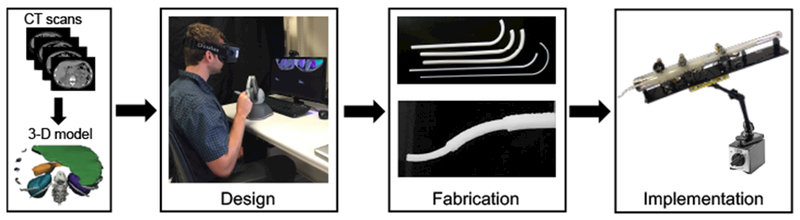
The proposed patient- and procedure-specific design workflow includes a 3D reconstruction of the anatomy based on medical images, followed by the design and fabrication of the personalized tools, and finally deployment of the robot in a procedure.
Acknowledgment
This work was supported in part by the National Institutes of Health through R01 EB018849 and a National Science Foundation Graduate Research Fellowship. The authors would like to thank Robert Webster III, Richard Hendrick, and Hunter Gilbert for their help with kinematic computations, Simon DiMaio and Intuitive Surgical, Inc. for the use of the da Vinci foot pedals, and Mark Cutkosky and David Camarillo for contributions to the artificial and ex vivo tissue testing concepts.
References
- 1.Amanov E, Nguyen T-D, and Burgner-Kahrs J (2015). Additive manufacturing of patient-specific tubular continuum manipulators. Proc. SPIE, 9415:94151–94159. [Google Scholar]
- 2.Anor T, Madsen JR, and Dupont PE (2011). Algorithms for design of continuum robots using the concentric tubes approach: A neurosurgical example. In Proc. IEEE Int. Conf. Robotics and Automation, pages 667–673. [DOI] [PMC free article] [PubMed] [Google Scholar]
- 3.Bergeles C, Gosline AH, Vasilyev NV, Codd PJ, Pedro J, and Dupont PE (2015). Concentric tube robot design and optimization based on task and anatomical constraints. Transactions on Robotics, 31(1):67–84. [DOI] [PMC free article] [PubMed] [Google Scholar]
- 4.Brok J, Treger TD, Gooskens SL, van den Heuvel-Eibrink MM, and Pritchard-Jones K (2016). Biology and treatment of renal tumours in childhood. European Journal of Cancer, 68:179–195. [DOI] [PubMed] [Google Scholar]
- 5.Burgner J, Gilbert HB, and Webster RJ III (2013). On the Computational Design of Concentric Tube Robots: Incorporating Volume-Based Objectives. In Proc. IEEE Int. Conf. Robotics and Automation, pages 1185–1190. [Google Scholar]
- 6.Burgner J, Rucker DC, Gilbert HB, Swaney PJ, Russell PT III, Weaver KD, and Webster RJ III (2014). A Telerobotic System for Transnasal Surgery. IEEE/ASME Trans. Mechatronics, 19(3):996–1006. [DOI] [PMC free article] [PubMed] [Google Scholar]
- 7.Burgner J, Swaney PJ, Bruns TL, Clark MS, Rucker DC, Burdette EC, and Webster RJ III (2012). An Autoclavable Steerable Cannula Manual Deployment Device: Design and Accuracy Analysis. ASME Journal of Medical Devices, 6(4):410071–410077. [DOI] [PMC free article] [PubMed] [Google Scholar]
- 8.Burgner-Kahrs J, Gilbert HB, Granna J, Swaney PJ, and Webster RJ III (2014). Workspace characterization for concentric tube continuum robots. In IEEE/RSJ Int. Conf. Intelligent Robots and Systems, pages 1269–1275. [Google Scholar]
- 9.Dupont P, Lock J, Itkowitz B, and Butler E (2010a). Design and control of concentric-tube robots. IEEE Trans. Robotics, 26(2):209–225. [DOI] [PMC free article] [PubMed] [Google Scholar]
- 10.Dupont PE, Lock J, and Itkowitz B (2010b). Real-time position control of concentric tube robots. In Proc. IEEE Int. Conf. Robotics and Automation, pages 562–568. [DOI] [PMC free article] [PubMed] [Google Scholar]
- 11.Gilbert H and Webster R III (2013). Can concentric tube robots follow the leader? In Proc. IEEE Int. Conf. Robotics and Automation, pages 4881–4887. [DOI] [PMC free article] [PubMed] [Google Scholar]
- 12.Gilbert HB, Rucker DC, and Webster RJ III (2016). Concentric Tube Robots: State of the Art and Future Directions, pages 253–269. Springer International Publishing. [Google Scholar]
- 13.Gilbert HB and Webster RJ III (2016). Rapid, Reliable Shape Setting of Superelastic Nitinol for Prototyping Robots. IEEE Robotics and Automation Letters, 1(1):98–105. [DOI] [PMC free article] [PubMed] [Google Scholar]
- 14.Gosline A, Vasilyev N, Butler E, Folk C, Cohen A, Chen R, Lang N, Del Nido P, and Dupont P (2012). Percutaneous intracardiac beating-heart surgery using metal mems tissue approximation tools. International Journal of Robotics Research, 31(9):1081–1093. [DOI] [PMC free article] [PubMed] [Google Scholar]
- 15.Graves CM, Slocum AH, Gupta R, and Walsh CJ (2012). Towards a compact robotically steerable thermal ablation probe. In Proc. IEEE Int. Conf. Robotics and Automation, pages 709–714. [Google Scholar]
- 16.Ha J, Park FC, and Dupont PE (2017). Optimizing tube precurvature to enhance the elastic stability of concentric tube robots. IEEE Transactions on Robotics, 33(1):22–37. [DOI] [PMC free article] [PubMed] [Google Scholar]
- 17.Hendrick RJ, Mitchell CR, Herrell SD, and Webster RJ III (2015). Hand-held transendoscopic robotic manipulators: A transurethral laser prostate surgery case study. I. J. Robotics Res, 34(13):1559–1572. [DOI] [PMC free article] [PubMed] [Google Scholar]
- 18.Kodama Y, Oishi A, Nagasawa N, Nakayama K, Tamada M, and Machado L (2009). Effect of sterilization dose on electron beam irradiated biodegradable polymers and coconut fiber based composites. In Int. Conf. Nuclear Atlantic. [Google Scholar]
- 19.Morimoto TK, Greer JD, Hsieh MH, and Okamura AM (2016). Surgeon design interface for patient-specific concentric tube robots. In Int. Conf. on Biomedical Robotics and Biomechatronics, pages 41–48. [DOI] [PMC free article] [PubMed] [Google Scholar]
- 20.Morimoto TK, Hawkes EW, and Okamura AM (2017). Design of a compact actuation and control system for flexible medical robots. IEEE Robotics and Automation Letters, 2(3):1579–1585. [DOI] [PMC free article] [PubMed] [Google Scholar]
- 21.Morimoto TK and Okamura AM (2016). Design of 3-D printed concentric tube robots. IEEE Trans. Robotics, 32(6):1419–1430. [DOI] [PMC free article] [PubMed] [Google Scholar]
- 22.Pantelidou M, Challacombe B, McGrath A, Brown M, Ilyas S, Katsanos K, and Adam A (2016). Percutaneous radiofrequency ablation versus robotic-assisted partial nephrectomy for the treatment of small renal cell carcinoma. Cardiovascular and Interventional Radiology, 39(11):15950–1603. [DOI] [PMC free article] [PubMed] [Google Scholar]
- 23.Rucker DC, Jones BA, and Webster RJ III (2010). A Geometrically Exact Model for Externally Loaded Concentric Tube Continuum Robots. IEEE Trans. on Robotics, 26(5):769–780. [DOI] [PMC free article] [PubMed] [Google Scholar]
- 24.Sears P and Dupont P (2006). A steerable needle technology using curved concentric tubes. In IEEE/RSJ Int. Conf. Intelligent Robots and Systems, pages 2850–2856. [Google Scholar]
- 25.Solomon J (2015). Numerical Algorithms: Methods for Computer Vision, Machine Learning, and Graphics. A. K. Peters, Ltd., Natick, MA, USA. [Google Scholar]
- 26.Swaney PJ, Croom JM, Burgner J, Gilbert HB, Rucker DC, Russell PT III, Weaver KD, and Webster RJ III (2012). Design of a Quadramanual Robot for Single-Nostril Skull Base Surgery. In ASME Dynamic Systems and Control, volume 3, pages 387–393. [Google Scholar]
- 27.Tadakuma K, Tadakuma R, Ioka K, Kudo T, Takagi M, Tsumaki Y, Higashimori M, and Kaneko M (2012). Omnidirectional driving gears and their input mechanism with passive rollers. In IEEE/RSJ Int. Conf. Intelligent Robots and Systems, pages 2881–2888. [Google Scholar]
- 28.Torres L, Webster RJ III, and Alterovitz R (2012). Task-oriented Design of Concentric Tube Robots using Mechanics-based Models. In IEEE/RSJ Int. Conf. Intelligent Robots and Systems, pages 4449–4455. [DOI] [PMC free article] [PubMed] [Google Scholar]
- 29.Webster R, Okamura A, and Cowan N (2006). Toward active cannulas: Miniature snake-like surgical robots. In IEEE/RSJ Int. Conf. Intelligent Robots and Systems, pages 2857–2863. [Google Scholar]
- 30.Webster R, Romano J, and Cowan N (2009). Mechanics of precurved-tube continuum robots. IEEE Trans. Robotics, 25(1):67–78. [Google Scholar]
- 31.Webster R III, Romano J, and Cowan N (2008). Kinematics and calibration of active cannulas. In IEEE Int. Conf. Robotics and Automation, pages 3888–3895. [Google Scholar]
- 32.Xu R, Atashzar SF, and Patel RV (2014). Kinematic instability in concentric-tube robots: Modeling and analysis. In Biomedical Robotics and Biomechatronics (2014 5th IEEE RAS & EMBS International Conference on, pages 163–168. IEEE. [Google Scholar]