Abstract
Virtual reality (VR) head-mounted displays are an attractive technology for viewing intrasurgical optical coherence tomography (OCT) volumes because they liberate surgeons from microscope oculars. We demonstrate real-time, interactive viewing of OCT volumes in a commercial HTC Vive immersive VR system using previously reported ray casting techniques. Furthermore, we show interactive manipulation and sectioning of volumes using handheld controllers and guidance of mock surgical procedures in porcine eyes exclusively within VR. To the best of our knowledge, we report the first immersive VR-OCT viewer with stereo ray casting volumetric renders, arbitrary sectioning planes, and live acquisition support. We believe VR-OCT volume displays will advance ophthalmic surgery towards VR-integrated surgery.
OCIS codes: (170.4500) Optical coherence tomography, (330.4460) Ophthalmic optics and devices, (100.6890) Three-dimensional image processing
1. Introduction
Optical coherence tomography (OCT) is an increasingly popular imaging modality for intrasurgical guidance in ophthalmology [1–21]. Incorporation of OCT scanners into traditional surgical microscopes for live cross-sectional and volumetric imaging at video rates has only further established OCT as a key intraoperative technology [22–27]. Ophthalmic surgeons often struggle, however, as consumers of OCT datasets due to poor visualization. OCT, intraoperative or otherwise, simply does not benefit the surgeon if they cannot find the desired cross-section, orient the volume intuitively, or appreciate the spatial relationships between tissue structures in three dimensions. The OCT community has consequently invested considerable effort into developing visualization techniques that give surgeons the high-quality views they need. These techniques include stereoscopic systems for use inside [28,29] and outside [30,31] the operating room and heads-up displays (HUDs) incorporated into microscopes for intraoperative augmented reality [15,32–35].
Virtual reality (VR) has drawn attention as a method for displaying complex images, including OCT volumes. Formerly an expensive research technology, VR is commercially available in 3D monitors/televisions and even relatively high-end consumer-oriented immersive head-mounted displays (HMDs). HMDs exhibit several notable advantages for VR compared with 3D TVs and HUDs [36]. HMDs not only offer a much larger field of view (potentially the full 4π sr) to display imagery, owing to users’ unrestricted head motion, but also permit users to move through a virtual space. Even while immersed, video feedthrough of HMD-mounted and other cameras can maintain users’ connection with the physical world. In the ophthalmic surgery context, we believe immersed surgeons can even gain a heightened situational awareness through careful context-dependent feedthrough of relevant information, such as patient status data displays (e.g., vital signs monitors) and pre- or intra-operative imaging visualizations. Far from “blinded” to the outside world, an HMD-immersed surgeon potentially has access to much more information than they could see when obligated to direct their attention through the microscope oculars alone. With increasingly clever VR interfaces that make navigating virtual menus and switching between video displays intuitive, the immersed surgeon can simply look around the operating room as usual while simultaneously benefiting from OCT and other data visualizations.
To provide a compelling visual experience, however, immersive VR systems require complete control over users’ visual inputs. Unfortunately, such extensive control can predispose users to motion sickness. If, when users move their heads, the VR system fails to track that motion sufficiently accurately (tracking error) or fails to render the viewed scene sufficiently quickly (rendering lag), the discordance between users’ visual and vestibular senses may induce simulator sickness [37]. VR manufacturers have suitably addressed tracking error by synthesizing data from accurate fixed-base HMD pose trackers and responsive HMD-integrated inertial measurement units. Similarly, they have mitigated the rendering lag by imposing high frame rate requirements on VR applications and by predicting the HMD pose one or more frames ahead. For many consumer VR systems, this means rendering at no less than 90 fps.
VR for OCT visualization is not new, however. In 2013, Schulze et al. explored non-immersive 3D TV-based VR for viewing OCT volumes using a texture-based approximation to ray casting for volumetric rendering [38]. In 2015, Bukaty et al. reported viewing of segmentation results from macular traction datasets in seated immersive VR with the Oculus Rift (Oculus VR; Irvine, CA) using a mesh reconstruction approach [39]. We extend these works by developing an interactive VR-OCT viewer for both static and live datasets using the Vive (HTC; New Taipei City, Taiwan) for room-scale immersive VR. Rather than using texture-based approximations or mesh reconstructions, we optimize our previously reported graphics processing unit (GPU) enhanced ray casting algorithms [40] for high-quality volumetric rendering at 180 fps (90 fps per eye) as required for immersive VR. In particular, we structure our GPU algorithms to capitalize on the frame rate differential between volume acquisition and VR rendering (e.g., 10 fps vs. 180 fps). This paper describes GPU approaches and data organization techniques for high-frame rate ray casting, presents performance comparisons for optimizations with their quality trade-offs, and demonstrates guidance of mock surgical procedures exclusively by live OCT and video feedthrough from within immersive VR.
2. Volume ray casting
Volume ray casting is a direct volumetric rendering technique for visualizing 3D volumes. In medical imaging applications, the volume is typically a scalar field (e.g., reflectance or density) with shading and classification transfer functions. These transfer functions assign application-dependent color and opacity, respectively, to each voxel. Volume ray casting samples and blends these colors and opacities along imagined rays to generate a representative 2D image [41].
2.1. Ray generation
Figure 1 shows the typical scheme for a 3D rendering with perspective in graphics environments like OpenGL (The Khronos Group; Beaverton, OR) and DirectX (Microsoft; Redmond, WA). The rendering pairs a “world” of geometries with a “camera” that projects this world into an image. The camera’s field of view and vantage point are defined by projection and modelview matrices, respectively. The projection matrix P defines a pyramid extending from the camera’s focal point along the −z axis, which the camera’s near and far clip planes truncate into a frustum. Objects within the frustum participate in the render; objects outside do not. The modelview matrix M positions the camera’s frustum in the world such that it contains the objects of interest. Both matrices are 4 × 4 and operate on homogenous coordinates.
Fig. 1.
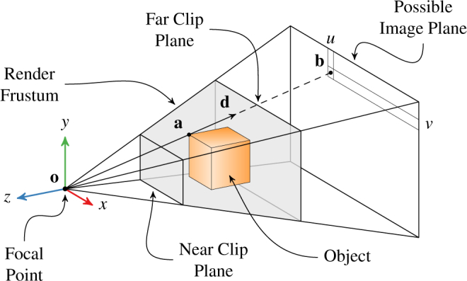
Diagram of projective geometry for a perspective 3D rendering. The 3D object point a in camera coordinates is projected to the 2D image point b with pixel coordinates (u, v). The ray d from o passes through both a and b.
After transforming all object points into camera coordinates with M, each 3D object point a = (x, y, z) is projected into a 2D point b = (u, v) on the image plane of pixels. Any plane parallel to the xy-plane at a negative z offset suffices as an image plane because the pixel size scales with the z offset. Mathematically, the perspective projection process is expressed as
| (1) |
where the leading factor of −z arises from the perspective projection. As shown in Fig. 1, u and v determine b’s position on the image plane, but w only reflects the depth of a. This is consistent with a 3D ray’s complete specification by two parameters. Thus, u and v uniquely determine the ray from the focal point that passes through a.
Although many schemes for ray generation in volume ray casting exist, choosing rays that correspond to pixels is particularly helpful when working with both volume and mesh objects. When volume ray casting using rays from the focal point through the image plane’s pixels, the volume behaves like a normal object posed in the 3D scene. The resulting volumetric render coincides pixel-for-pixel with the 3D graphics render such that compositing them together is trivial. Furthermore, each ray’s origin and direction vectors can be extracted from P and M, which completely define the 3D graphics render. The ray origin is simply o = (0, 0, 0) in camera coordinates. The ray direction d for a given pixel b is determined from Eq. (1) by noting that it holds for any z. Choosing z = −1 conveniently eliminates this parameter. Furthermore, w does not affect the ray, so it is chosen as zero. Solving for x and y, which define the ray in camera coordinates, gives
| (2) |
which is subsequently normalized such that ║d║ = 1. To obtain the ray in world coordinates, the ray origin is transformed by M−1,
| (3) |
and the ray direction is rotated by M−1,
| (4) |
Notably, M−1 always exists because M is a homogenous transformation matrix. P−1 exists if neither clip plane includes the origin. This is typically required by the graphics environment.
2.2. Sampling
Fig. 2 depicts how the previously generated rays sample the volume’s color and opacity. The rays propagate outward from the common origin in fixed steps along their respective directions of travel. Specifically, the ray’s ith step is at position
| (5) |
where Δt is the step size and t0 is the initial propagation distance. t0 is chosen per ray to avoid unnecessary steps before the ray enters the volume. At every step, the rays sample the volume’s color c (x) and opacity α(x). These application-dependent functions are designed to reveal or highlight certain volume features. For example, shading is frequently incorporated into α(x) to give the volume an appearance of structure.
Fig. 2.
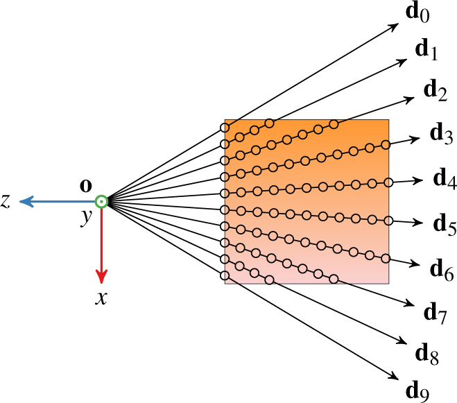
Illustration of sampling the volume with ten rays. Each ray samples the volume at a fixed interval from entry until exit. Circles denote the sample positions.
Evaluating c(x) and α(x) incurs the largest computational cost of volume ray casting. These functions internally query the volume, or do so indirectly via gradient computations. Unfortunately, it is desirable to keep Δt small to preserve render quality, which increases the sample count. If Δt is too large, the resulting render may not capture smaller structures within the volume. The target application typically enforces an upper bound on Δt such that optimizations other than increasing Δt are preferred for expediting slow renders. Furthermore, each ray takes samples at unique positions; because the rays all propagate in different directions from the same point, their paths never cross. The sample count is consequently proportional to the ray count as well.
2.3. Blending
Blending combines each ray’s samples into a single pixel value with color and opacity. Many techniques in 3D graphics exist for this purpose; however, the front-to-back method is particularly advantageous because samples are blended in the order the ray encounters them. Once the pixel has accumulated sufficient opacity, the ray can “exit early” to skip subsequent samples without significantly affecting the pixel’s final color. As the ray encounters each sample, it performs front-to-back blending according to
| (6) |
| (7) |
where cr,i and αr,i are the accumulated color and opacity at the ith step. Blending is initialized with cr,0 = 0 and αr,0 = 0 for a perfectly black and completely transparent initial pixel. The final pixel color and opacity are cr,n and αr,n, respectively, where n is the index of the final step. These recursive equations can be expressed as
| (8) |
| (9) |
in closed form [40]. In practice, the recursive form lends to more efficient computation if cr,i−1 and αr,i−1 are cached. For color renders, each channel blends independently according to Eq. (6).
3. GPU optimizations
We applied four distinct optimizations to perform ray casting as in [40] but at the high frame rates needed for immersive VR systems. The first two improve data storage and computational efficiency without significant render quality reduction. The second two, however, eliminate expensive computations and thereby degrade the rendered volume’s visual appearance. Notably, we performed these optimizations without sampling density or resolution reductions. Table 1 summarizes the optimizations and introduces the letter-based convention we use for referencing combinations of them. A numeric suffix after the configuration letters specifies the render resolution (e.g., PCNI-512 at 512 × 512 pixels). An underscore indicates that a particular optimization class is left unspecified (e.g., E_LF refers to both ESLF and ECLF). The “baseline” configuration from [40] is ESLF.
Table 1.
Letter Convention for Render Configurations
| Quality | Class | Letter | Configuration |
|---|---|---|---|
| Preserving | Data Layout | E | intensity |
| P | gradient packing | ||
| K | voxel packing | ||
|
| |||
| Kernel | S | sequential (2D) | |
| C | concurrent (3D) | ||
|
| |||
| Degrading | Texture Interpolation | L | trilinear |
| N | nearest | ||
|
| |||
| Data Type | F | floating-point (32 bits) | |
| I | integer (8 bits) | ||
3.1. Data layout
Data layout has a significant impact on rendering runtime because it affects the volume sampling latency. This latency is exaggerated for large volumes, which may exceed texture memory cache sizes, and for renders with shading and edge enhancement, which require multiple samples for gradient computations. In a render with gradient-based shading especially, a single ray may incur several hundred gradient computations depending upon its propagation depth and step size. The gradient is computed with central finite differences in three dimensions for six total volume texture lookups (E). GPUs optimize texture memory for spatial locality, yet the number of rays and the volume’s storage size can still cause performance-reducing cache misses. We avoided these six texture lookups in two separate techniques: gradient packing and voxel packing.
Gradient packing (P) combines volume sampling and gradient computation into a single texture lookup. We accomplish this by precomputing the gradient for the entire volume once at voxel resolution and interleaving it with the volume intensity as a four-vector. The x, y, and z vector components store the vector-valued gradient whereas the w vector component stores the scalar-valued volume intensity. This approach is effective because the volume is rendered much faster (180 fps) than it is acquired (10 fps for typical real-time OCT systems). Consequently, the gradient is computed only when the volume is updated and cached for many render frames until the next update. Interleaving the gradient and intensity thus reduces each ray propagation step to a single volume texture lookup, even with gradient-based shading. Because ray casting uses voxel resolution for its gradient computation, precomputing the gradient at the voxel level does not significantly affect render quality. Storage of three additional values does quadruple the volume size in memory, especially when a 32 bit floating-point data type is used. If an 8 bit data type is chosen instead, the packed gradient fits into the storage size of a single 32 bit floating-point scalar.
Voxel packing (K) combines volume sampling, gradient computation, and trilinear interpolation into a single texture lookup. We accomplished this by bit-packing each voxel’s eight corner values as 8 bit integers into one 32 bit integer two-vector using the scheme in Fig. 3. As with gradient packing, voxel packing is performed once and then reused in subsequent renders until the next volume update. When sampling the volume during ray propagation, we round that ray’s position to the containing voxel and retrieve that voxel’s corners via a single texture lookup with nearest-neighbor interpolation. This approach avoids the additional volume samples needed behind the scenes for a texture lookup with trilinear interpolation. With the eight voxel corners available, we manually perform trilinear interpolation within the render kernel to compute the volume intensity and gradient at the ray’s actual position. The resulting render quality is slightly degraded because the manual interpolation performs poorly at the voxel faces. Nevertheless, voxel packing provides quality comparable to trilinear interpolation without requiring additional volume samples. The storage of one additional 32 bit integer does double the volume size in memory, but not as much as gradient packing with a 32 bit floating-point four-vector.
Fig. 3.
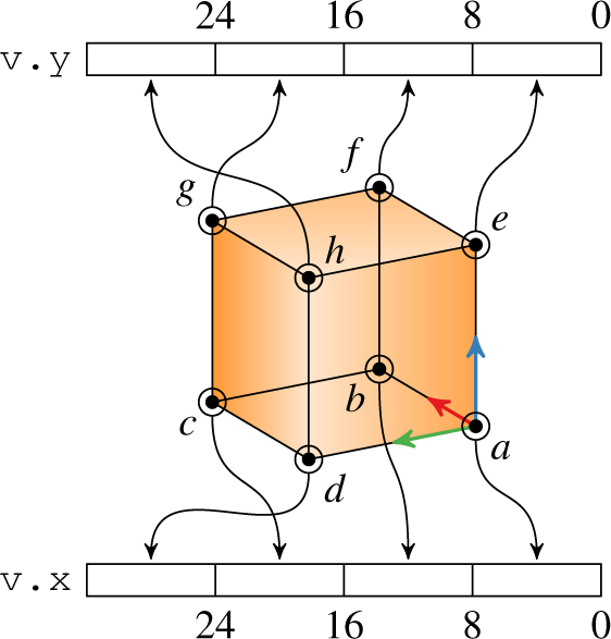
Storage arrangement for voxel packing. The voxel’s eight corner values (a – h) are stored as 8 bit integers in a 32 bit integer two-vector (v). Numbers indicate bit offsets into each integer.
3.2. Kernel launch
The GPU kernel launch configuration (e.g., block size) affects performance through streaming multiprocessor scheduling. We improved GPU occupancy by combining ray casting kernels for the left and right eyes into a single kernel invocation (C) rather than invoking the same render kernel once for each eye (S). This was accomplished with a third kernel dimension that serves as an index into an array of render parameters. We extended this approach to allow an arbitrary number of concurrent ray castings as needed in 360° recordings, for example. In practice, aggregating multiple identical kernels into a single monolithic one allows the GPU to achieve greater efficiency in streaming multiprocessor usage. This optimization does not alter the ray casting computation and thus does not affect render quality or storage requirements.
3.3. Interpolation and data type
We reduced GPU computation by converting from texture trilinear interpolation (L) to nearest-neighbor interpolation (N). This improves performance by avoiding the extra texture lookups otherwise performed. Furthermore, when using nearest-neighbor interpolation, the volume texture data type can be changed from 32 bit floating point (F) to 8 bit integer (I) without affecting quality because the interpolation result is independent of data type. In [40], the volume intensity was originally an 8 bit integer so no precision was gained from floating-point storage. This data type change further increases performance by reducing the volume texture size in memory by a factor of four. The decreased memory size increases the fraction of the volume that will fit in the texture cache, which reduces cache misses.
4. Interactive virtual reality viewer
Our VR-OCT viewer supports interactive posing and sectioning of static and live volumes while meeting the rendering requirements of immersive VR. We implemented our viewer using OpenGL and OpenVR (Valve Corporation; Bellevue, WA), which allows us to integrate with any OpenVR-supported hardware. Section 4.1 provides an overview of the viewer’s rendering pipeline while Section 4.2 focuses on live sectioning. Section 4.3 extends the pipeline to handle live volume datasets, and then Section 4.4 describes the user interactivity scheme.
4.1. Pipeline
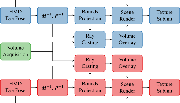
The rendering pipeline is divided into three stages that execute sequentially every frame: pose update, volumetric render, and compositing (Fig. 4). During pose update, we queried the VR tracking system for updated HMD and controller poses. In accordance with OpenVR recommended practices, we used the pose velocity to predict the HMD and controller poses at the instant when the HMD screen redraws. We used these predicted poses to drive the eye view matrices and controller input poses for ray casting and user interactivity features, respectively.
Fig. 4.
Virtual reality display pipeline for right (bottom, red) and left (top, blue) eyes. The pipeline begins (left) with OCT volume acquisition (green) or OpenVR pose update and completes (right) with HMD texture submissions.
The volume render stage is responsible for producing an image from the volumetric datasets stored in GPU texture memory. Typical real-time viewing applications render OCT volumes at 512 × 512 pixels and 30 fps. In contrast, rendering at the Vive’s native resolution and frame rate of 1512 × 1680 pixels and 90 fps, respectively, is difficult without building a small render farm. Ray casting only within the screen area containing the volume significantly reduces this rendering burden. Thus, we computed the on-screen volume bounding rectangle and performed ray casting at 512 × 512 pixels only within that rectangle using the view and projection matrices for each eye. This optimization allowed us to concentrate rays in the OCT screen region while sharing the view and projection matrices with the scene camera. The volumetric render image consequently remained sharp even when occupying a small screen region. The process was performed independently for each eye because of the difference in view and projection matrices between eyes. Additional volumes could be readily incorporated here, if needed, with further bounding box projections and ray castings at the associated computational expense. For later compositing steps, we considered the ray casting intensity as the transparency channel of a uniform intensity texture. This produced an effect where less dense regions of the OCT volume appear more translucent rather than less bright.
The compositing stage combines the OCT volumetric render image with the 3D scene to produce the final image for each eye. Compositing is done at OpenVR’s recommended Vive oversampling resolution of 1512 × 1680 pixels. For simplicity, we divided the VR scene into the background, volume, and foreground layers. The scene background layer contained static models to help orient the user (e.g., a floor). The volume layer included only the OCT volumetric render image. The scene foreground layer contained interactive models with which the user manipulated the volume (e.g., Vive controller models). To build the final image, the scene background layer was first rendered onto a black background using the eye’s view and projection matrices. We chose a completely black background to enhance volume visibility. Similarly, we included only an unobtrusive wireframe floor to orient the user without detracting from the volume’s visibility. Next, a rectangle textured with the volumetric render that matched the volume’s on-screen bounding rectangle was rendered in orthographic projection. We enabled OpenGL texture linear interpolation for upsampling or downsampling the volumetric render image as needed. Finally, the scene foreground was rendered. We performed these renders into OpenGL framebuffer objects using the HMD-specific non-visible pixel mask and submitted the resultant textures to OpenVR for presentation.
4.2. Live sectioning
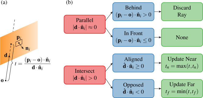
We implemented dynamic volume sectioning by defining a set of cut planes that bounded ray propagation. The ith cut plane is defined by a point pi and a normal vector in the volume space. Similarly, each ray is defined by an origination point o and direction vector d (Fig. 5(a)). The cut plane divides the volume into the hidden half-space for which and the visible half-space for which , where x is a point in the volume. Rays passing through the hidden half-space accumulate no additional color and opacity. Conversely, rays passing through the visible half space accumulate color and opacity as in Eq. (6). When more than one cut plane is present, the volume’s only visible portion is that region within the intersection of every cut plane’s visible half-space, which is a convex hull by construction. We call this region the visible convex hull (VCH). Applying cut planes is thus equivalent to ray casting as if the volume were completely transparent except within the VCH.
Fig. 5.
(a) Ray-plane intersection geometry for a non-parallel ray. (b) Decision tree from left to right for a cut plane’s effect on a given ray.
Rather than explicitly computing the complete VCH, we instead determined the distance along its propagation vector at which each ray enters (tn) and exits (tf) the VCH. If the ray intersects the VCH, it is then propagated from o + tnd to o + tfd according to Eq. (5) with t0 = tn for n = ⌈(tf − tn)/Δt⌉ steps. The distances tn and tf are readily computed using the ray-plane intersection equation as tn = max D and tf = min D where
| (10) |
for k cut planes with points {pi} and normals . If the ray is parallel to any cut plane such that and lies behind the cut plane such that , it is discarded; otherwise, the ray is unaffected by that cut plane. Figure 5(b) summarizes this procedure, which is performed independently for each ray.
4.3. Live volumes
We supported volume texture updates to enable viewing and manipulation of live OCT volumes within the VR environment. For live volumes, viewing and acquisition are traditionally collocated because the OCT engine is responsible for display. In contrast, we elected to stream OCT volumes across an Ethernet network from the OCT engine to the VR system and thereby decouple viewing from acquisition. This is advantageous in that dedicated computational resources can be allocated separately to viewing and acquisition and in that multiple viewers can display the same acquired data concurrently in different locations. Capitalizing upon this networked approach, however, requires attention to efficient data handling as the processed OCT volume is no longer immediately available in the viewer’s device (GPU) memory.
To support remote viewing, we implemented a network server in our acquisition software that streamed sets of processed B-scans. Once the acquisition GPU completed processing of a B-scan batch, these B-scans were copied to host (CPU) memory and written out to all connected network clients. This incurred little overhead because B-scans were already copied from device to host memory for writing to persistent storage. The VR-OCT viewer implemented a network client that received each B-scan batch and incrementally updated the volume texture. To minimize delays, the viewer performed concurrent network reads, host-to-device transfers, and texture updates. A dedicated CPU thread read each B-scan batch into rotating pinned host memory buffers. When a given buffer was filled, a host-to-device transfer for that buffer was issued in a dedicated “copy” GPU stream and a matching update kernel invocation was issued in a dedicated “update” GPU stream. The update kernel performed gradient or voxel packing, depending upon the active data layout scheme, and directly updated the volume texture. A GPU event was used to synchronize the kernel execution and transfer without host intervention. Serializing all update kernels in the same GPU stream ensured that the volume texture was updated in the acquisition order.
4.4. Interactivity
We added interactivity to the VR-OCT viewer with two handheld Vive controllers for posing and sectioning the volume. The user independently switched each controller between posing and sectioning using specific positions on the directional pad.
In posing mode, the user could translate, rotate, and scale the volume. When the user depressed the trigger of one controller only, the relative motion of the controller was then mapped onto the volume. This produced an effect where the user grabbed and moved the volume as if grasped by the hand. When the user depressed the triggers of both controllers, the controllers’ relative motion affected the volume’s rotation and scale. Increasing or decreasing the distance between the controllers magnified or minified the volume, respectively. This allowed the user to zoom the volume in or out, much like the pinch gesture common on touchscreen-enabled devices. Rotating the controllers about each other applied the same rotation to the volume. This produced an effect where the user grabbed the volume with two hands and pivoted it about its center.
In sectioning mode, a translucent cut plane was drawn extending from the controller. When the user partially depressed the controller’s trigger, the volume was sectioned with that cut plane, which moved with the controller. When the user completely depressed the trigger, the volume was persistently sectioned with that cut plane. Subsequently releasing the trigger allowed the user to start another live section. The persistent cut planes were defined in the volume’s local coordinate system and therefore moved, rotated, and scaled with the volume. All cut planes were cleared using a button on the controller.
5. Methods
We evaluated our VR-OCT viewer’s rendering latency, live volume latency, and user experience through benchmarking and testing. Sections 5.1 and 5.2 describe the OCT and graphics systems, respectively, for these evaluations. Sections 5.3 through 5.5 present our testing methodology.
5.1. OCT system parameters
We used two different OCT systems to evaluate our VR-OCT viewer. System A was the OCT system previously reported in [42]. This system illuminated a spectrally-balanced interferometer with a 1060 nm swept-frequency source (Axsun Technologies; Bileraca, MA) at a 100 kHz A-scan rate. The optical signal detection chain used a 1.8 GS/s digitizer (AlazarTech; Quebec, Canada) to measure the output of a balanced photoreceiver (Thorlabs; Newton, NJ). We acquired 1327 × 1024 × 128 voxel volumes at 0.39 vol/s for ray casting latency characterization (Section 5.3). System B illuminated a Mach-Zender topology interferometer with a 1060 nm swept-frequency source (Axsun Technologies; Bileraca, MA) at a 100 kHz A-scan rate. Again, the optical signal detection chain used a 1.8 GS/s digitizer (AlazarTech; Quebec, Canada) to measure the output of a balanced photoreceiver (Thorlabs; Newton, NJ). We acquired 500 × 500 × 128 voxel volumes at 1.56 vol/s for live volume latency analysis (Section 5.4) and 481 × 301 × 96 voxel volumes at 3.46 vol/s for user experience assessment (Section 5.5).
5.2. Ray casting parameters
Our VR computer featured dual GPUs; a NVIDIA GTX 1080 was dedicated to ray casting whereas all other graphics processing (e.g., scene compositing) was performed on a NVIDIA GTX 670. We used CUDA (NVIDIA; Santa Clara, CA) with “fast math” enabled for GPU programming. The ESLF-512 configuration (see Table 1) represented baseline performance for all metrics. Ray propagations used a step size of 0.01 in normalized texture space, were limited to 500 steps, and exited early at 95 % opacity in all configurations. All renderings used the parameters given in Table 2 according to their definitions in [40].
Table 2.
Ray Casting Rendering Parameters
| Edge Enhancement
|
Feature Enhancement
|
Depth-Based Shading
|
Phong Shading
|
||||
|---|---|---|---|---|---|---|---|
| Constant | Value | Constant | Value | Constant | Value | Constant | Value |
| kg 1 | 0.25 | kf 1 | 0.05 | kd 1 | 1.2 | kp 1 | 1.2 |
| kg 2 | 0.3 | kf 2 | 0.4 | kd 2 | 4 | kp 2 | 0.45 |
| kd 3 | 0.5 | kp 3 | 0.6 | ||||
| kp 4 | 1 | ||||||
5.3. Ray casting latency characterization
We characterized ray casting latency for compatible configurations from Table 1 using a standardized battery of stereo renders. For a given configuration, we rendered static volumes at 512 × 512 pixels from views uniformly distributed over a sphere and recorded ray casting kernel execution durations using the NVIDIA Visual Profiler. To elicit worst-case performance, we used synthetic, all-zero volumes sized 1 × 1 × 1 voxels and 256 × 256 × 256 voxels to examine computational overhead and caching effects, respectively. To elicit typical performance, we used a static 1327 × 1024 × 128 voxel anterior segment volume acquired with System A. Each viewing angle was repeated at four distances for a total of 648 renders per volume and per configuration, after 100 initial “warm-up” renders. We evaluated all possible configurations with the E and P data layouts except those using trilinear interpolation with integer data types (LI). Such configurations were excluded because they produced unacceptably low render quality. For the most optimized configuration (PCNI), we considered renders at 768 × 768 pixels and 1024 × 1024 pixels as well to determine if higher resolutions were possible while still meeting the render deadline. Additionally, we evaluated the KCNI configuration as an alternative to trilinear interpolation (L) for preserving render quality.
5.4. Live volume latency characterization
We characterized live volume latency by measuring the time required for changes in System B’s acquired signal to affect an ongoing stereo render. With its photoreceiver unpowered, we artificially alternated System B’s signal between zero and saturation in software by overwriting acquired A-scans and streamed processed B-scans in chunks of 4 to the VR computer over a 1 Gbps Ethernet network. Furthermore, we adapted our software to synchronize a light emitting diode (LED) with the artificial signal level alternations. In the ongoing ray casting with the PCNI-512 configuration, saturated B-scans rendered as pure white (high brightness) whereas zero B-scans rendered as pure transparency onto the black background (low brightness). Using a Grasshopper3 (FLIR Systems; Wilsonville, OR) camera viewing both the LED and HMD oculars in a dimly-lit environment, we recorded 600 fps video that captured the delay between LED illumination and HMD brightness change with approximately 1.67 ms resolution. In addition, we recorded the render and update kernel execution durations with the NVIDIA Visual Profiler to assess the impact of live updates on VR frame rate.
5.5. User experience assessment
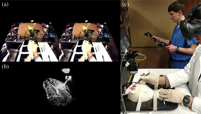
We assessed user experience with regards to image quality and usability through two sets of mock surgical procedures in ex vivo porcine eyes. In each procedure, an experienced anterior segment surgeon performed partial-thickness passes through the cornea with a 6-0 suture needle. We imaged each pass with System B in real-time and streamed processed B-scans in chunks of 32 to the VR computer over a 1 Gbps Ethernet network. For the “observed” procedure set, the surgeon executed passes with the unaided eye and on-screen OCT while a nearby observer wearing the HMD followed along in VR-OCT. The operator used interactive volume posing and sectioning to reveal needle depth during a series of passes. For the “guided” procedure set, the surgeon guided the same needle passes exclusively with VR-OCT. The surgeon wore the HMD which displayed live OCT from System B in addition to external video feedthrough from the HMD’s front-facing camera to improve situational awareness. We presented external video on a plane fixed in the surgeon’s field of view that aligned the camera’s perspective with the physical world and then rendered the OCT volume over this plane with colorization to provide extra contrast (see Fig. 10(a) for example). To facilitate surgeon interaction in VR-OCT, an assistant manipulated the volume using VR controllers at the surgeon’s request by viewing a screen that mirrored the HMD. To keep handheld controller motions intuitive, the assistant and surgeon faced the same direction in the tracked VR environment.
Fig. 10.
Demonstration of mock corneal surgery in a porcine eye guided by VR-OCT and HMD camera feedthrough (a). The surgeon passes a needle through the cornea without a microscope (b) and uses an assistant for volume manipulation (c). See Visualization 2 (5.2MB, mp4) for full video.
We also assessed render quality by comparing the output of incrementally optimized configurations from Table 1. For quality comparison purposes, we compared renders with a standardized volume and viewing angle to the baseline ESLF configuration. Images for quality analysis were taken directly from the ray casting output and did not include other 3D scene elements. We examined these images overall and at magnification for preservation of fine detail and introduction of artifacts.
6. Results
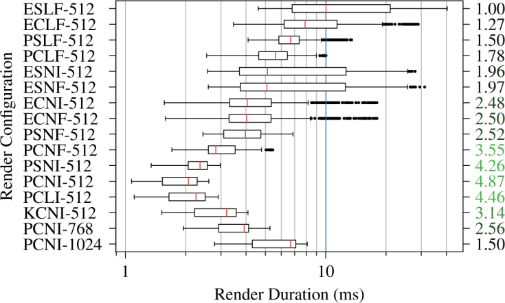
We performed renders in sixteen different configurations for a total of 31,104 stereo ray castings across the three test volumes when evaluating ray casting latency. Figs. 6 and 7 show ray casting latency and speedup factors for the 1 × 1 × 1 voxel and 256 × 256 × 256 voxel all-zero volumes, respectively. The most optimized PCNI-512 configuration achieved speedup factors of 3.08 and 4.87 from baseline for the respective volumes. The quality-preserving KCNI-512 configuration achieved speedup factors of 1.73 and 3.14 from baseline for the same volumes. PCNI-768 and PCNI-1024 showed much more modest speedup factors, however, especially for the single voxel volume. Fig. 8 shows ray casting latency and overrun rates for the 1327 × 1024 × 128 voxel typical volume. The overrun rate is the fraction of stereo render durations that exceeded 11.1 ms, the interval corresponding to 90 fps. The PCNI-512 and KCNI-512 configurations achieved 0 % and 1 % overrun rates, respectively, compared to 100 % for the baseline ELSF-512 configuration. Both PCNI-768 and PCNI-1024 demonstrated 0 % overrun rates.
Fig. 6.
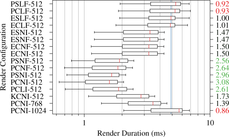
Stereo ray casting latency and speedup (right) by render configuration for a 1 × 1 × 1 voxel transparent volume. The vertical blue line indicates the median latency in the baseline ESLF-512 configuration.
Fig. 7.
Stereo ray casting latency and speedup (right) by render configuration for a 256 × 256 × 256 voxel transparent volume. The vertical blue line indicates the median latency in the baseline ESLF-512 configuration.
Fig. 8.
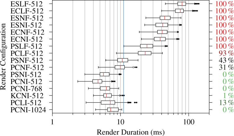
Stereo ray casting latency and render overrun rate (right) by render configuration for a 1327 × 1024 × 128 voxel typical OCT volume. The vertical blue line indicates the 90 fps deadline at 11.1 ms.
We measured 32 ± 8 ms delay from acquisition to display across 13 zero/saturation transitions when assessing live volume latency. At 90 fps, this corresponds to a 3 ± 1 frame delay. OCT processing in batches of four B-scans introduced a fixed latency of approximately 10 ms, leaving approximately 22 ± 8 ms of latency attributable to network transfer and volume update. During live updates, the VR pipeline maintained a median frame interval of 11.2 ms, corresponding to 89.3 fps, over 833 renders with 375 updates. The longest observed frame interval was 11.7 ms. The render and update kernels accounted for 98.3 % and 1.6 % of GPU execution time, respectively.
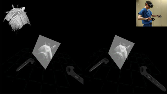
Fig. 9 illustrates the observer’s VR-OCT experience during the “observed” procedure set. The VR rendering pipeline operated without noticeable frame drops or lag, despite live volume updates. The immersed user viewed volumes from any perspective by looking and walking around or inside them. Similarly, the user readily manipulated the volume’s pose and applied live cut planes through the controller-based interaction modes to reveal needle bite depth. Fig. 10 shows the surgeon’s VR-OCT experience during the “guided” procedure set. The surgeon successfully visualized the tool and completed needle passes guided exclusively in VR-OCT. The live OCT visualization provided sufficient detail to identify and maneuver the needle tip near the cornea without microscope assistance. Furthermore, the surgeon effectively used external video feedthrough to orient themselves in the procedure environment. They had difficulty, however, controlling the tool outside of the OCT field of view due to low camera resolution. The assistant found the HMD display mirror adequate for satisfying the surgeon’s volume manipulation requests.
Fig. 9.
Example view through the HMD as the user (top right) sections a live OCT volume (top left) to reveal needle bite depth. Insets are not visible in HMD. See Visualization 1 (14.6MB, mp4) for full video.
Fig. 11 shows render quality obtained with incremental optimization. Gradient packing (P) slightly altered the output from baseline (E) but did not significantly degrade its quality. Switching from trilinear (L) to nearest-neighbor (N) interpolation yielded noticeably fuzzy output which masked previously visible volume features. Converting from floating-point (F) to integer (I) data types with nearest-neighbor interpolation did not significantly alter quality. Voxel packing (K), however, greatly restored render quality but not without introducing some gradient-related artifacts.
Fig. 11.
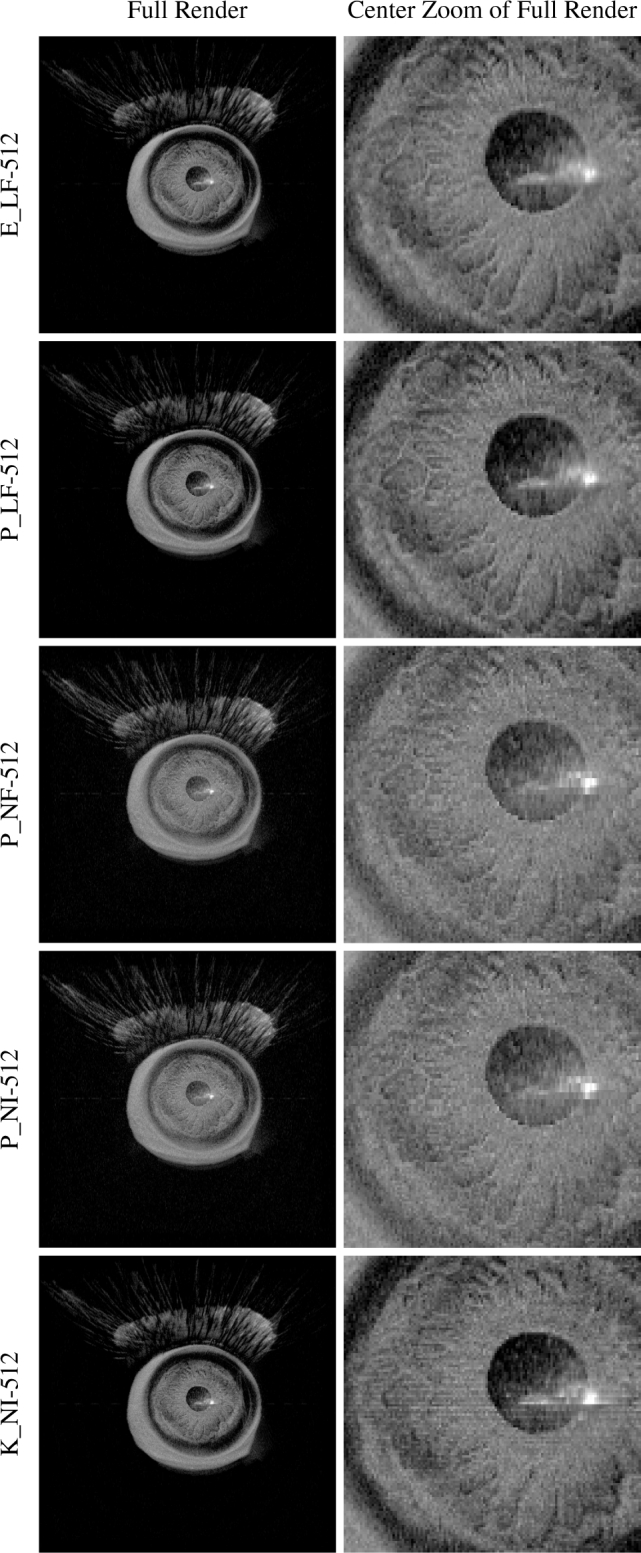
Render quality by configuration for a 1327 × 1024 × 128 voxel typical OCT volume. Optimization increases progressively from top to bottom until the K data layout is used to restore interpolation. Quality is independent of kernel launch configuration (Section 3.2).
7. Discussion
Our VR-OCT viewer demonstrated successful visualization of OCT volumes without significant frame drops or lag at 90 fps. The primary drivers of this success were the large speedups obtained with certain optimization combinations. The combination responsible for the most speedup varied with the volume type and size, however. For the computation-bound renders in Fig. 6, changing from floating-point (F) to integer (I) data type produced the single greatest observed speedup (PCLF → PCLI). Despite this potential, PCLI yielded poor quality output and later overran a substantial fraction of typical volume renders in Fig. 8. Gradient packing (P) produced a superior speedup but only when combined with nearest-neighbor (N) interpolation (P_LF → P_NF). Surprisingly, P_LF performed worse than E_LF, most likely due to four-vector rather than scalar trilinear interpolation. The combinations in P_NF avoid this interpolation for a speedup. In contrast, the broader effects of kernel launch and data types are not seen until the larger, memory-bound volumes in Figs. 7 and 8. These optimizations produce smaller gains which the quick renders for small volumes do not elicit.
In meeting VR requirements, we unfortunately conceded some render quality. As seen in Fig. 11, our best performing configuration, PCNI-512, yielded the fuzziest renders, primarily due to its avoidance of trilinear interpolation (L). Partially restoring quality with KCNI-512 barely “meets” the 90 fps deadline for a typical volume in Fig. 8 and actually overruns in 1 % of renders. On the other hand, if somewhat fuzzy renders are acceptable, PCNI scales to 1024 × 1024 pixels while still meeting deadlines. Resolution is thus more available than quality, which is a trade-off that can be made on a case-by-case basis. We expect the continual advancement of GPU technology will eventually bring larger texture caches and faster interpolation to improve this situation. That said, because each render is independent, ray casting for the two eyes could be split over two GPUs with existing technology. This would double the number of host-to-device transfers, but as long as the volume is rendered many more times than it is updated, an incremental speedup of up to two would be possible. This approach could in theory be extended by splitting up individual eye renders into parts for separate GPUs to process, but expanding beyond several GPUs may require multiple computers or specialized hardware. Distributing live updates to all GPUs may become difficult in this case.
The viewer’s interactivity features provided new ways to visualize OCT volumes. Users could walk through, carry, spin, and look at volumes that floated comfortably in front of them, towered through the ceiling, or fit compactly in their hand. Furthermore, the ability to add multiple live sectioning planes offered new insights into OCT volumes, especially when viewing inside hollow structures. These new viewing techniques are relevant even beyond intrasurgical use; there exist opportunities for VR-OCT in educational settings and collaborative, shared VR experiences. Notably, our VR-OCT viewer is not specific to ophthalmology. Any scalar 3D volume can be displayed and sectioned in our optimized viewer.
Intrasurgical interactivity via handheld controllers presented a significant problem, however, primarily because the surgeon’s hands were already busy with surgical tools. In addition to maintaining surgeon situational awareness during VR immersion (Section 1), this is a potential barrier to VR-OCT’s introduction into the operating room. We avoided the issue here by introducing an assistant exclusively for VR control, although other workarounds include motion capture-compatible surgical tools and camera-based eye or hand tracking. These solutions are fundamentally insufficient, however. Even if surgeons had convenient and ergonomic VR interactivity, they would find themselves limited to small visualization changes while operating because large view rotations would sever their intuitive connection to their tools [43]. Consequently, surgeons would suffer from misalignment between their hands and viewed tool motions, offsetting the benefits of intraoperative volumetric imaging. Even worse, consciously compensating for such misalignment would incur a significant performance penalty. We believe that surgical robots offer the best solution for intrasurgical VR interactivity because they free surgeons from their tools and can restore or even improve performance [44]. With their hand motions computationally transformed into the intended tool motions, surgeons are no longer needlessly tethered in an otherwise unrestricted VR environment.
8. Conclusion
To the best of our knowledge, we have reported the first immersive VR-OCT viewer with stereo ray casting volumetric renders, arbitrary sectioning planes, and live acquisition support. We have demonstrated this viewer’s suitability for both review of pre-recorded volumes and guidance of mock surgical procedures in porcine eyes. VR-OCT brings the benefits of interactivity, full field of view display, and unrestricted head orientation to ophthalmic surgeons. We believe that VR-OCT may eventually become standard for intrasurgical navigation and medical education in OCT-guided ophthalmic procedures.
Acknowledgments
The authors would like to thank the Duke Advanced Research in Swept Source/Spectral Domain OCT Imaging Laboratory for their support.
A typographical correction was made to the author listing.
Funding
National Institutes of Health (R01-EY023039, F30-EY027280, T32-GM007171); NVIDIA Global Impact Award (2016)
Disclosures
AK: Leica Microsystems (P), ClarVista (C). JI: Leica Microsystems (P, R), Carl Zeiss Meditec (P, R).
References and links
- 1.Carrasco-Zevallos O. M., Viehland C., Keller B., Draelos M., Kuo A. N., Toth C. A., Izatt J. A., “Review of intraoperative optical coherence tomography: technology and applications,” Biomed. Opt. Express 8, 1607–1637 (2017). 10.1364/BOE.8.001607 [DOI] [PMC free article] [PubMed] [Google Scholar]
- 2.Dayani P. N., Maldonado R., Farsiu S., Toth C. A., “Intraoperative use of handheld spectral domain optical coherence tomography imaging in macular surgery,” Retina 29, 1457–1468 (2009). 10.1097/IAE.0b013e3181b266bc [DOI] [PMC free article] [PubMed] [Google Scholar]
- 3.Lee L. B., Srivastava S. K., “Intraoperative spectral-domain optical coherence tomography during complex retinal detachment repair,” Ophthalmic. Surg. Lasers Imaging 42 Online, 71–74 (2011). [DOI] [PubMed] [Google Scholar]
- 4.Geerling G., Muller M., Winter C., Hoerauf H., Oelckers S., Laqua H., Birngruber R., “Intraoperative 2-dimensional optical coherence tomography as a new tool for anterior segment surgery,” Arch. Ophthalmol. 123, 253–257 (2005). 10.1001/archopht.123.2.253 [DOI] [PubMed] [Google Scholar]
- 5.Lankenau E., Klinger D., Winter C., Malik A., Müller H. H., Oelckers S., Pau H.-W., Just T., Hüttmann G., Combining Optical Coherence Tomography (OCT) with an Operating Microscope (Springer, 2007), pp. 343–348. [Google Scholar]
- 6.Tao Y. K., Ehlers J. P., Toth C. A., Izatt J. A., “Intraoperative spectral domain optical coherence tomography for vitreoretinal surgery,” Opt. Lett. 35, 3315–3317 (2010). 10.1364/OL.35.003315 [DOI] [PMC free article] [PubMed] [Google Scholar]
- 7.Binder S., Falkner-Radler C. I., Hauger C., Matz H., Glittenberg C., “Feasibility of intrasurgical spectral-domain optical coherence tomography,” Retina 31, 1332–1336 (2011). 10.1097/IAE.0b013e3182019c18 [DOI] [PubMed] [Google Scholar]
- 8.Ehlers J. P., Tao Y. K., Farsiu S., Maldonado R., Izatt J. A., Toth C. A., “Integration of a spectral domain optical coherence tomography system into a surgical microscope for intraoperative imaging,” Invest. Ophthalmol. Vis. Sci. 52, 3153 (2011). 10.1167/iovs.10-6720 [DOI] [PMC free article] [PubMed] [Google Scholar]
- 9.Hahn P., Migacz J., O’Donnell R., Day S., Lee A., Lin P., Vann R., Kuo A., Fekrat S., Mruthyunjaya P., Postel E. A., Izatt J. A., Toth C. A., “Preclinical evaluation and intraoperative human retinal imaging with a high-resolution microscope-integrated spectral domain optical coherence tomography device,” Retina 33, 1328–1337 (2013). 10.1097/IAE.0b013e3182831293 [DOI] [PMC free article] [PubMed] [Google Scholar]
- 10.Hahn P., Migacz J., O’Connell R., Izatt J. A., Toth C. A., “Unprocessed real-time imaging of vitreoretinal surgical maneuvers using a microscope-integrated spectral-domain optical coherence tomography system,” Graefes Arch. Clin. Exp. Ophthalmol. 251, 213–220 (2013). 10.1007/s00417-012-2052-2 [DOI] [PMC free article] [PubMed] [Google Scholar]
- 11.Steven P., Le Blanc C., Velten K., Lankenau E., Krug M., Oelckers S., Heindl L. M., Gehlsen U., Hüttmann G., Cursiefen C., “Optimizing descemet membrane endothelial keratoplasty using intraoperative optical coherence tomography,” JAMA Ophthalmology 131, 1135–1142 (2013). 10.1001/jamaophthalmol.2013.4672 [DOI] [PubMed] [Google Scholar]
- 12.Tao Y. K., Srivastava S. K., Ehlers J. P., “Microscope-integrated intraoperative OCT with electrically tunable focus and heads-up display for imaging of ophthalmic surgical maneuvers,” Biomed. Opt. Express 5, 1877–1885 (2014). 10.1364/BOE.5.001877 [DOI] [PMC free article] [PubMed] [Google Scholar]
- 13.Ehlers J. P., Tam T., Kaiser P. K., Martin D. F., Smith G. M., Srivastava S. K., “Utility of intraoperative optical coherence tomography during vitrectomy surgery for vitreomacular traction syndrome,” Retina 34, 1341–1346 (2014). 10.1097/IAE.0000000000000123 [DOI] [PMC free article] [PubMed] [Google Scholar]
- 14.Ehlers J. P., Kaiser P. K., Srivastava S. K., “Intraoperative optical coherence tomography using the RESCAN 700: Preliminary results from the DISCOVER study,” Br. J. Ophthalmol. 98, 1329–1332 (2014). 10.1136/bjophthalmol-2014-305294 [DOI] [PMC free article] [PubMed] [Google Scholar]
- 15.Ehlers J. P., Srivastava S. K., Feiler D., Noonan A. I., Rollins A. M., Tao Y. K., “Integrative advances for OCT-guided ophthalmic surgery and intraoperative OCT: Microscope integration, surgical instrumentation, and heads-up display surgeon feedback,” PLoS One 9, e105224 (2014). 10.1371/journal.pone.0105224 [DOI] [PMC free article] [PubMed] [Google Scholar]
- 16.Hahn P., Carrasco-Zevallos O., Cunefare D., Migacz J., Farsiu S., Izatt J. A., Toth C. A., “Intrasurgical human retinal imaging with manual instrument tracking using a microscope-integrated spectral-domain optical coherence tomography device,” Translational Vision Science & Technology 4, 1 (2015). 10.1167/tvst.4.4.1 [DOI] [PMC free article] [PubMed] [Google Scholar]
- 17.Nam D. H., Desouza P. J., Hahn P., Tai V., Sevilla M. B., Tran-Viet D., Cunefare D., Farsiu S., Izatt J. A., Toth C. A., “Intraoperative spectral domain optical coherence tomography imaging after internal limiting membrane peeling in idiopathic epiretinal membrane with connecting strands,” Retina 35, 1622–1630 (2015). 10.1097/IAE.0000000000000534 [DOI] [PMC free article] [PubMed] [Google Scholar]
- 18.Lytvynchuk L., Glittenberg C., Binder S., “The use of intraoperative spectral domain optic coherence tomography in vitreoretinal surgery: The evaluation of efficacy,” Acta Ophthalmologica 93, 667 (2015). 10.1111/j.1755-3768.2015.066725988844 [DOI] [Google Scholar]
- 19.Heindl L. M., Siebelmann S., Dietlein T., Hüttmann G., Lankenau E., Cursiefen C., Steven P., “Future prospects: Assessment of intraoperative optical coherence tomography in ab interno glaucoma surgery,” Current Eye Research 40, 1288–1291 (2015). 10.3109/02713683.2014.995311 [DOI] [PubMed] [Google Scholar]
- 20.Siebelmann S., Steven P., Cursiefen C., “Intraoperative optical coherence tomography: Ocular surgery on a higher level or just nice pictures?” JAMA Ophthalmology 133, 1133–1134 (2015). 10.1001/jamaophthalmol.2015.2396 [DOI] [PubMed] [Google Scholar]
- 21.Siebelmann S., Steven P., Hos D., Hüttmann G., Lankenau E., Bachmann B., Cursiefen C., “Advantages of microscope-integrated intraoperative online optical coherence tomography: Usage in Boston keratoprosthesis type I surgery,” J. Biomed. Opt. 21, 16005 (2016). 10.1117/1.JBO.21.1.016005 [DOI] [PubMed] [Google Scholar]
- 22.Shieh C., DeSouza P., Carrasco-Zevallos O., Cunefare D., Izatt J. A., Farsiu S., Mruthyunjaya P., Kuo A. N., Toth C. A., “Impact of microscope integrated OCT on ophthalmology resident performance of anterior segment maneuvers in model eyes,” Invest. Ophthalmol. Vis. Sci. 56, 4086 (2015). [DOI] [PMC free article] [PubMed] [Google Scholar]
- 23.Pasricha N. D., Shieh C., Carrasco-Zevallos O. M., Keller B., Izatt J. A., Toth C. A., Kuo A. N., “Real-time microscope-integrated OCT to improve visualization in DSAEK for advanced bullous keratopathy,” Cornea 34, 1606–1610 (2015). 10.1097/ICO.0000000000000661 [DOI] [PMC free article] [PubMed] [Google Scholar]
- 24.Toth C. A., Carrasco-Zevallos O., Keller B., Shen L., Viehland C., Nam D. H., Hahn P., Kuo A. N., Izatt J. A., “Surgically integrated swept source optical coherence tomography (SSOCT) to guide vitreoretinal (VR) surgery,” Invest. Ophthalmol. Vis. Sci. 56, 3512 (2015). [Google Scholar]
- 25.Carrasco-Zevallos O. M., Keller B., Viehland C., Shen L., Waterman G., Todorich B., Shieh C., Hahn P., Farsiu S., Kuo A. N., Toth C. A., Izatt J. A., “Live volumetric (4D) visualization and guidance of in vivo human ophthalmic surgery with intraoperative optical coherence tomography,” Sci. Rep. 6, 31689 (2016). 10.1038/srep31689 [DOI] [PMC free article] [PubMed] [Google Scholar]
- 26.Probst J., Hillmann D., Lankenau E. M., Winter C., Oelckers S., Koch P., Hüttmann G., “Optical coherence tomography with online visualization of more than seven rendered volumes per second,” J. Biomed. Opt. 15, 1–4 (2010). 10.1117/1.3314898 [DOI] [PubMed] [Google Scholar]
- 27.Jian Y., Wong K., Sarunic M. V., “Graphics processing unit accelerated optical coherence tomography processing at megahertz axial scan rate and high resolution video rate volumetric rendering,” J. Biomed. Opt. 18, 1–5 (2013). 10.1117/1.JBO.18.2.026002 [DOI] [PubMed] [Google Scholar]
- 28.Ehlers J. P., Uchida A., Srivastava S., “THE INTEGRATIVE SURGICAL THEATER: Combining intraoperative optical coherence tomography and 3D digital visualization for vitreoretinal surgery in the DISCOVER study,” Retina, epub ahead of print (2017). 10.1097/IAE.0000000000001999 [DOI] [PMC free article] [PubMed]
- 29.TrueVision Systems , “NGENUITY,” http://www.truevisionsys.com/ngenuity.html.
- 30.Aaker G. D., Gracia L., Myung J. S., Borcherding V., Banfelder J. R., D’Amico D. J., Kiss S., “Volumetric three-dimensional reconstruction and segmentation of spectral-domain OCT,” Ophthalmic. Surg. Lasers Imaging 42 Suppl, S116–S120 (2011). 10.3928/15428877-20110627-11 [DOI] [PubMed] [Google Scholar]
- 31.Kozak I., Banerjee P., Luo J., Luciano C., “Virtual reality simulator for vitreoretinal surgery using integrated OCT data,” Clin. Ophthalmol. 8, 669–672 (2014). 10.2147/OPTH.S58614 [DOI] [PMC free article] [PubMed] [Google Scholar]
- 32.Roodaki H., Filippatos K., Eslami A., Navab N., “Introducing augmented reality to optical coherence tomography in ophthalmic microsurgery,” in “IEEE International Symposium on Mixed and Augmented Reality,” (2015), pp. 1–6. [Google Scholar]
- 33.Shen L., Carrasco-Zevallos O., Keller B., Viehland C., Waterman G., Hahn P. S., Kuo A. N., Toth C. A., Izatt J. A., “Novel microscope-integrated stereoscopic heads-up display for intrasurgical optical coherence tomography,” Biomed. Opt. Express 7, 1711–1726 (2016). 10.1364/BOE.7.001711 [DOI] [PMC free article] [PubMed] [Google Scholar]
- 34.Horvath S. J., “The optical coherence tomography microsurgical augmented reality system (OCT-MARS): A novel device for microsurgeries,” Ph.D. thesis, Carnegie Mellon University, Pittsburgh, PA: (2016). [Google Scholar]
- 35.Carl Zeiss Meditec , “OPMI LUMERA 700 and RESCAN 700 from ZEISS,” https://www.zeiss.com/meditec/us/products/ophthalmology-optometry/glaucoma/therapy/surgical-microscopes/opmi-lumera-700.html.
- 36.Shen L., Keller B., Carrasco-Zevallos O., Viehland C., Bhullar P. K., Waterman G., Kuo A. N., Toth C. A., Izatt J. A., “Oculus Rift® as a head tracking, stereoscopic head mounted display for intra-operative OCT in ophthalmic surgery,” Invest. Ophthalmol. Vis. Sci. 57, 1701 (2016). [Google Scholar]
- 37.Buker T. J., Vincenzi D. A., Deaton J. E., “The effect of apparent latency on simulator sickness while using a see-through helmet-mounted display,” Human Factors 54, 235–249 (2012). 10.1177/0018720811428734 [DOI] [PubMed] [Google Scholar]
- 38.Schulze J. P., Schulze-Dobold C., Erginay A., Tadayoni R., “Visualization of three-dimensional ultra-high resolution OCT in virtual reality,” Stud. Health Technol. Inform. 184, 387–391 (2013). [PubMed] [Google Scholar]
- 39.Bukaty E., Glittenberg C. G., Binder S., “Interactive, stereoscopic, three dimensional, virtual reality visualization of optical coherence data sets of vitreo-macular tractions before and after enzymatic vitreolysis,” Invest. Ophthalmol. Vis. Sci. 56, 5919 (2015). [Google Scholar]
- 40.Viehland C., Keller B., Carrasco-Zevallos O. M., Nankivil D., Shen L., Mangalesh S., Viet du T., Kuo A. N., Toth C. A., Izatt J. A., “Enhanced volumetric visualization for real time 4D intraoperative ophthalmic swept-source OCT,” Biomed. Opt. Express 7, 1815–1829 (2016). 10.1364/BOE.7.001815 [DOI] [PMC free article] [PubMed] [Google Scholar]
- 41.Levoy M., “Display of surfaces from volume data,” IEEE Computer Graphics and Applications 8, 29–37 (1988). 10.1109/38.511 [DOI] [Google Scholar]
- 42.Nankivil D., Waterman G., LaRocca F., Keller B., Kuo A. N., Izatt J. A., “Handheld, rapidly switchable, anterior/posterior segment swept source optical coherence tomography probe,” Biomed. Opt. Express 6, 4516–4528 (2015). 10.1364/BOE.6.004516 [DOI] [PMC free article] [PubMed] [Google Scholar]
- 43.DeJong B. P., Colgate J. E., Peshkin M. A., Mental Transformations in Human-Robot Interaction (Springer, Netherlands, 2011), vol. 1010 of Intelligent Systems, Control and Automation: Science and Engineering, book section 3, pp. 35–51. [Google Scholar]
- 44.Draelos M., Keller B., Toth C., Kuo A., Hauser K., Izatt J., “Teleoperating robots from arbitrary viewpoints in surgical contexts,” in “IEEE/RSJ International Conference on Intelligent Robots and Systems (IROS),” (2017), pp. 2549–2555. [Google Scholar]


