Abstract
Macroscopic structures that undergo rapid and reversible stiffness transitions can serve as functional polymeric materials for many applications in robotics and medical devices. Thermomechanical phase transitions can provide a suitable mechanism for transient control of mechanical properties. However, the characteristic time scale for actuation is large and dictated by the dimensions of the structure. Embedding vascular networks within bulk polymers can reduce the characteristic length scale of the material and permit rapid and reversible thermomechanical transitions. Here we report perfusable bulk materials with embedded microvascular networks that can undergo rapid and reversible stiffness transitions. Acrylate-based thermoplastic structures exhibit storage moduli with a dynamic range between E’ = 1.02 ± 0.07 GPa and E’ = 13.5 ± 0.7 MPa over time scales as small as 2.4 ± 0.5 s using an aqueous thermal perfusate. The spatiotemporal evolutions of temperature profiles were accurately predicted using finite element simulation and compared to experimental values. Rigid-compliant transitions were leveraged in a demonstration in which a microvascularized device was used to grasp an external object without the aid of moving parts.
Keywords: microfluidics, functional polymers, microfabrication, reconfigurable materials
1. Introduction
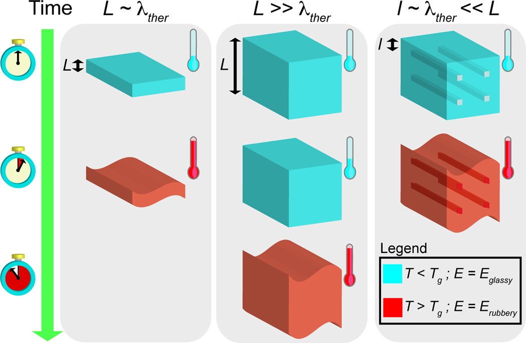
Natural organisms utilize highly specialized microstructures that permit rapid control of mechanical properties of biological materials. Rigid-compliant transitions serve many functions including protection from predators and actuation of structural components. Sea cucumbers (Cucumaria frondosa) utilize rapid reversible collagen linking to control the rigidity of the endoskeleton.[1] There are also many examples of synthetic materials and devices that utilize similar mechanisms including neural implants for brain-machine interfaces[2] and robotics.[3] Hydrogen-bonded hygroscopic polymeric networks with elastic modulus E = 540 ± 32.1 GPa can be converted into ultra-compliant networks with E = 4.58 ± 0.404 MPa upon hydration.[4] Structures that undergo rapid reversible transformations in mechanical properties could be useful in a number of applications related to medical devices and soft robotics. Microvascular networks fabricated using polymers with moderate glass transition temperatures (Tg) serve as a central strategy in the design and fabrication of materials that can undergo rapid and reversible rigid-compliant transitions in mechanical properties. Vascular networks facilitate thermoregulation, nutrient distribution, healing, and actuation of tissue structures in higher order organisms.[5,6] Vascular networks reduce the characteristic diffusion length scale and facilitate mass transfer within bulk volumes. Vascularization using microfluidic channels has been utilized in various synthetic materials including cell-seeded microfluidic scaffolds, gas exchange units, self-healing polymers, deformable electronics and actuation of functionality in soft materials.[7–18] The ideal phase-change material would be capable of achieving rigid-compliant transformations that are rapid, reversible, occur at moderate temperatures, and achieve a dynamic range of elasticities that spans at least one order of magnitude. Polymeric materials that are impermeable to water and exhibit moderate glass transition temperatures (30 °C < Tg < 60 °C) are ideally suited for these applications.[19–23] Cost-effective polymers that are amenable to facile fabrication processes such as 3D printing are also desirable.[24–29] This report describes the use of bulk materials that can undergo rapid and reversible transitions in mechanical properties. This capability is achieved by integrating embedded microfluidic networks within bulk polymers (Figure 1) using 3D printing.
Figure 1.
Schematic of the general strategy used to accelerate stiffness transitions in thermoplastic structures. Utilizing a vascularized material design in bulk thermoplastics decreases the characteristic length-scale of the material. This reduction leads to accelerated heat transfer and stiffness transitions when compared to monolithic thermoplastics.
2. Results and Discussion
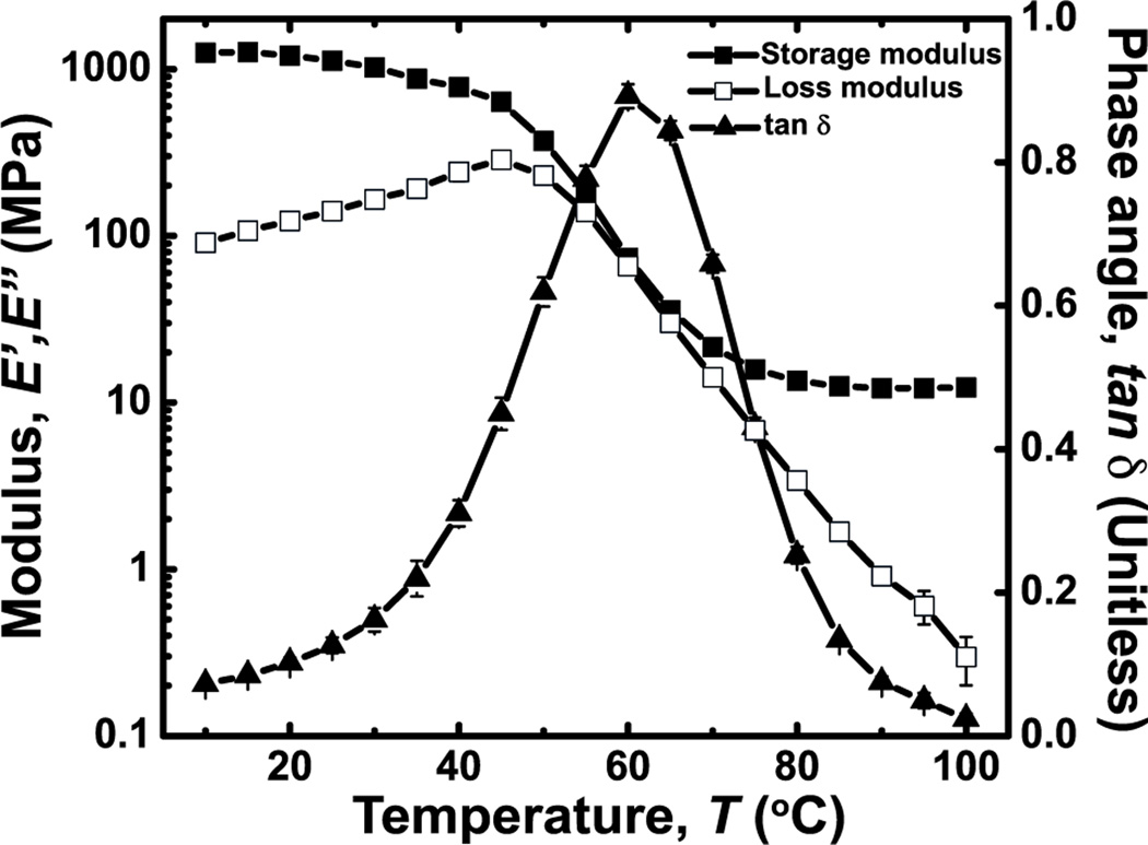
3D printing was selected as the fabrication method to produce thermoplastic polymers into microfluidic thermally activated materials. 3D printing is a generalizable fabrication technique that can process numerous polymers into complex geometries.[30] Acrylate-based thermoplastic polymer (ATPP) was selected as the thermally activated material for reversible modulation of rigid-compliant mechanical properties because it exhibits a Tg of 43 °C as measured by differential scanning calorimetry (DSC) and a softening temperature of 60 °C as measured by the phase angle (tan δ) (Figure 2, see Experimental). Complete glass-rubber transitions occur between 30 and 80 °C. The storage modulus spans nearly two orders of magnitude in this temperature range (E’g = 1.02 ± 0.07 GPa at T = 30 °C; E’r = 13.5 ± 0.7 MPa at T = 80 °C) (Figure 2). ATPP is the optimal polymeric composition because of the sharp thermomechanical transitions that are centered about moderate temperatures (Figure S1). ATPP is cost-effective and amenable to 3D printing of bulk structures.
Figure 2.
Thermomechanical properties of ATPP used in microfluidic thermally activated materials. Plots of the storage (E’) modulus, loss modulus (E’’), and tan δ of ATPP versus temperature from 10 to 100 °C indicate a softening temperature at Ts ~ 60 °C.
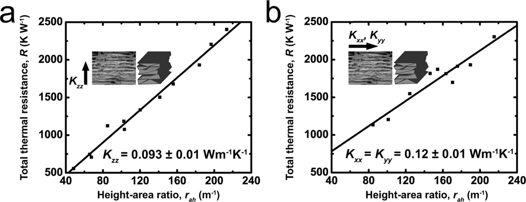
3D printed materials exhibit an intrinsic microstructural anisotropy due to the nature of the fabrication process. Layer-by-layer UV curing generates laminated multilayers of ATPP. The in-plane thermal conductivity (Kxx, Kyy) is expected to be larger compared to the transverse thermal conductivity (Kzz). The terms in the thermal conductivity matrix were measured to be Kxx = Kyy = 0.12 ± 0.01 W m−1 K−1 and Kzz = 0.093 ± 0.01 W m−1 K−1 (Figure 3). Anisotropy arises due to microscale defects between the ATPP layers along the z-axis.
Figure 3.
Plots of the total thermal resistance of ATPP versus height-area ratio of coupon geometries are shown. The thermal resistance is measured in ATPP samples with printing directions that are either oriented (a) orthogonal or (b) parallel to the direction of thermal conduction. These data are used to calculate the anisotropic thermal conductivities Kxx, Kyy and Kzz of ATPP.
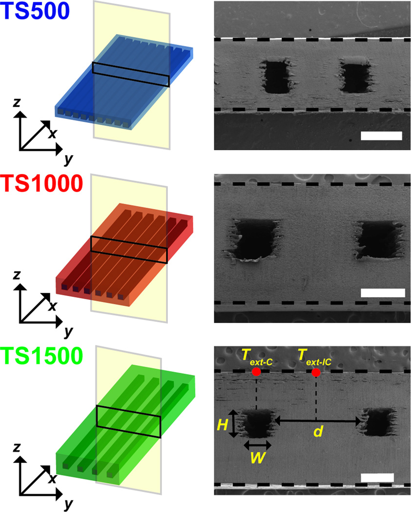
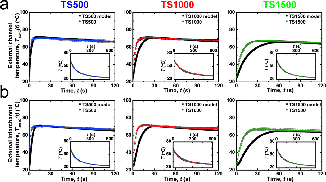
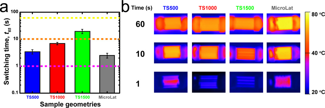
ATPP test structures with prescribed feature geometries were designed and fabricated. ATPP test structures were composed of rectangular microfluidic arrays with defined nominal cross-sectional areas (W = H = 500 µm) and inter-channel distances (d) where d = 500 (TS500), 1000 (TS1000), or 1500 µm (TS1500) (Table S1). The cross-sectional geometry of the microfluidic networks in test structures shows that the actual feature sizes are smaller than the nominal feature sizes due to reduced microchannel widths (Figure 4). Test structures with microchannel geometries are fabricated in low yields due to difficulty in removing non-crosslinked resin support material. Integrating microfluidic networks within ATPP does not significantly alter the temperature-dependent values of bulk E’ as measured by dynamic mechanical analysis (DMA) from 10 to 100 °C (Figure S3). Experimental and predicted temporal temperature profiles for microfluidic ATPP networks under aqueous thermal perfusate (To = 80 °C) are plotted in Figure 5. The spatiotemporal evolution of surface temperatures was measured at two external locations: (1) the region directly above the centerline of microfluidic channels (Text-C(t)); (2) the midplane of the ATPP structures between two adjacent microchannels (Text-IC(t)). The rate of increase during thermal perfusion for both Text-C(t) and Text-IC(t) increases as d is reduced. The time for complete modulus switching (t65) in glassy-rubbery transitions in ATPP occurs when Text-IC(t65) = 65 °C. The shortest and longest switching times were achieved for TS500 and TS1500, respectively.
Figure 4.
Schematics of microfluidic test structures used in this work. Scanning electron micrographs of the cross-section of each device indicate the relevant feature dimensions. Scale bars indicate 500 µm.
Figure 5.
A comparison of the experimental and predicted temperature profiles of microfluidic thermally activated materials perfused with media at 80 °C (n = 3). Temperatures are measured on the surface of test structures directly (a) above the centerline above microfluidic channels (Text-C) or (b) above the centerline between adjacent microfluidic channels (Text-IC). Insets show the cooling kinetics at ambient temperature after 120 s of thermal perfusion. The temporal surface evolution kinetics of the devices accelerates as the effective thermal diffusion length scale λ decreases. The fit between experimental and predicted external temperatures varies inversely with the characteristic thermal diffusion length scale (See text).
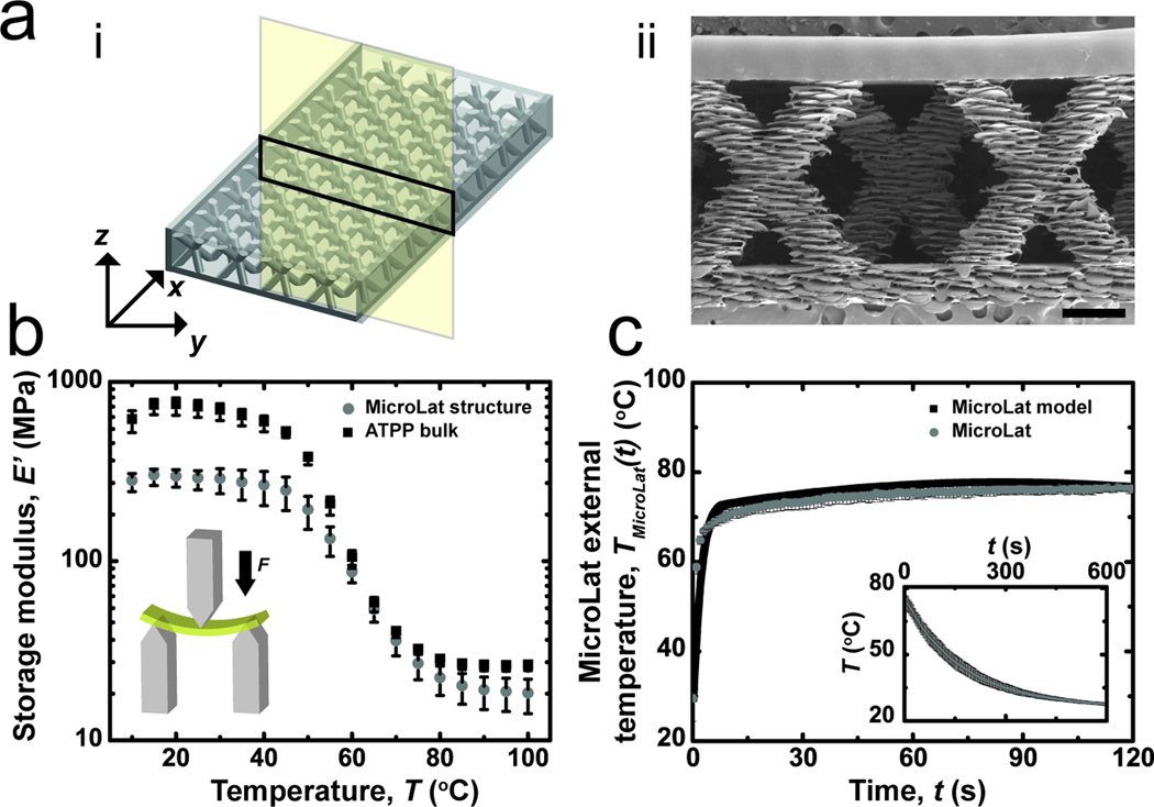
Microfluidic test structures accelerate phase transition kinetics by reducing the characteristic thermal diffusion length scale (λ). Parallel microfluidic arrays pose significant operational limitations that arise due to large pressure drops due to microchannel geometries. One half of the fluid velocity head is lost (KL = 0.5) as the fluid enters the microfluidic manifold due to dissipation of kinetic energy.[31] High-aspect ratio linear microchannels are challenging to fabricate with layer-by-layer rapid prototyping techniques such as 3D printing. Alternative geometries were designed to further reduce the time scale for glass-rubber phase transitions while increasing maximum achievable perfusion rates and fabrication yield. Microfluidic manifolds composed of alternating arrays of microscale struts (Figure 6; Figure S4) were fabricated using 3D printing. This cellular micro-lattice geometry (referred to as MicroLat) preserves structural integrity while reducing the effective volume fraction of bulk material ( ) within the microfluidic network.[32] The advantages of cellular microlattice geometries in metals for cooling and heat dissipation applications have been well documented.[33,34] Microstrut arrays reduce the characteristic length scale for thermal diffusion while permitting a higher flow rate through the macroscopic structure due to a reduced volume fraction of polymer (ϕpoly-MicroLat < ϕpoly-TS) (Figure S5). Microstrut arrays also reduce the pressure drop at the entrance compared to microchannel array geometries. ATPP MicroLat structures exhibit reduced extensive values of storage modulus E’ compared to test structures with microfluidic arrays as measured by DMA (Figure 6; Table S2). The dynamic range of storage moduli associated with rigid-compliant transitions is reduced in MicroLat geometries compared to bulk test structures due to a reduced volume fraction of ATPP in the former: ϕpoly-MicroLat < ϕpoly-TS < ϕpoly-bulk. Reduced extensive values of E’glass and E’rubber in MicroLat geometries were higher than predicted values due to the presence of the encapsulation layer, which is required to permit thermal perfusate delivery (Table S2; Figure S4).[35–37] In most open cellular solids such as foams, the deflection mechanism consists of flexion of cellular networks as well as extension/compression of the cellular material.[35] MicroLat geometries exhibit two types of defects within the strut: edge defects and incomplete lamination. These defects arise due to the accuracy restriction during 3D printing. The printer used in this study exhibits a typical accuracy of 20–85 µm in x, y and z printing direction (Table S3), which can result in lateral offsets and incomplete lamination between successive layers.
Figure 6.
a) (i) Schematic and (ii) micrograph of cross-section of MicroLat structure. Scale bar indicates 500 µm. b) Thermomechanical properties of both bulk and MicroLat structures composed of ATPP. c) Experimental and predicted temporal evolution of external temperatures of MicroLat structures (n = 3) measured using thermal media at 80 °C. Insets indicate cooling kinetics at ambient temperature after 120 s of thermal perfusion.
The temporal evolution of external temperature profiles for MicroLat geometries actuated using aqueous thermal perfusate (To = 80 °C) is shown (Figure 6c). Microfabricated MicroLat geometries exhibit accelerated glass-rubber phase transitions as assessed by reduced values of t65, MicroLat = 2.4 ± 0.5 s compared to t65, TS500 = 3.6 ± 1 s (Figure 7). This can be attributed to a reduced λMicroLat compared to λTS500 and increased flow rates of thermal perfusate. The characteristic timescale for thermomechanical phase transitions are governed by the diameter of the struts in MicroLat microstructures. Reducing the strut diameter will accelerate stiffness transitions during perfusion. Currently available 3D printing techniques can produce structures with minimum feature sizes of 10 µm or smaller,[38] albeit with increased fabrication time. Minimum feature sizes of approximately 100 µm could serve as a balance to achieve rapid phase transitions in centimeter-scale devices. These bounds will expand with increased sophistication of 3D printing technology. 3D printing can make arbitrarily complex structures very rapidly. This aspect renders 3D printing advantageous when designing structures with embedded vascular networks.
Figure 7.
a) Comparison of switching times (t65) for microfluidic and MicroLat structures. b) Thermal images at t = 1, 10, and 60 s for microfluidic test structures and MicroLat geometries.
Finite element models (FEM) predict the surface temperatures with accuracies that are both geometry- and location-dependent. FEM accurately predict the surface steady state temperature profiles (Text-C (t = ∞) and Text-IC (t = ∞)) for all geometries but underestimate the rate at which surface temperatures approach Text-C (t = ∞) and Text-IC (t = ∞) (Figure 5). This underestimation results in the overestimation of t65 times for all geometries. The extent of overestimation is proportional to λ (Figure S6). Microstructural defects along the x-y plane contribute to the systemic error because of increased perfusate penetration through defect networks compared to the z-direction, thereby decreasing the effective λ.
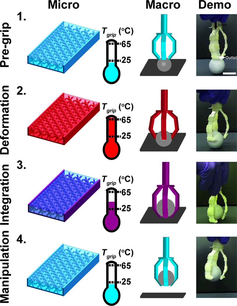
Macroscopic structures capable of rapid reversible rigid-compliant transitions could have applications as dynamic structural components in medical devices and soft robotics.[39–42] The utility of rapid actuation of mechanical properties was demonstrated by actuating a macroscopic gripper without the aid of moving parts using isothermal perfusate. The device features three arms composed of MicroLat unit structures that are joined with fluidic connectors. The initial temperature of the ATPP in the gripper (Tgrip < 25 °C) ensures that the device components are glassy and rigid (E’glass ~ 250 MPa) (Figure 8). Introduction of thermal perfusate (To = 80 °C) induces mechanical compliance at Tgrip > 65 °C (E’rubber ~ 20 MPa). Transiently compliant grippers ensconce the spherical object after which the ATPP material is restored to a glassy state (Tgrip < 25 °C). Manual manipulation of the object is possible thereafter. Reversible manipulation can be accelerated by integrating complementary cellular networks that can be selectively addressed with binary thermal perfusates (To,hot = 80 °C; To,cold = 20 °C). Complex manifold topologies could enable simultaneous spatially-defined rigid or compliant microdomains within the device superstructure.
Figure 8.
Microfluidic thermally activated materials can be assembled into a gripping device that can be actuated using thermal perfusion. Rapid rigid-compliant transitions can be used to grip objects without direct mechanical actuation. Four phases of device operation are shown: (1) Pre-grip phase (Tgrip < 25 °C) with rigid structures; (2) Deformation (Tgrip > 65 °C) where the compliant structures ensconce an object; (3) Integration (Tgrip < 65 °C) in which the rigid structures secure the object; (4) Manipulation (Tgrip < 25 °C) in which the rigid gripper elevates the object. Scale bar indicates 2 cm.
The general mechanism described herein could be useful for soft robotics in which structures can be manipulated in temporary states of mechanical compliance and remain static in the rigid state thereafter.[43] Other applications in robotics include reversible mechanical compliance in exoskeletons to permit egress through tortuous paths and dimensionally small orifices.[44] Rigid-compliant transitions induced by aqueous perfusates could be suitable for controlling surgical instruments such as those used in endovascular and gastrointestinal procedures. Programmable and segmented control of mechanical properties along the z-axis of cylindrical device geometries could permit device deployment through obstructions while reducing risk of damage and perforation of soft tissue structures. For example in endoscopy,[45] it has been observed that tissue perforations occur when forces > 54N is applied to the colon wall. Commercially-available endoscope cores consists of stainless steel or NiTinol which have a bulk material modulus of ~ 100 GPa.[46] Endoscopes with such cores have increased risk of causing perforations due to large forces applied on the tissue while negotiating tortuosity. Materials with modulus ranges from 20 MPa to 1 GPa would reduce potentially damaging mechanical insults on soft tissue structures while retaining structural integrity for surgical manipulation. Endovascular device applications are particularly suitable because of the potential ability to create high aspect ratio devices with millimetric features. The prospect for these envisioned applications and beyond will expand as the feature resolution, material capabilities, and parallelization of rapid prototyping techniques continues to advance.[47]
3. Conclusion
Integrating microfluidic networks within macroscopic form factors composed of thermoplastic polymers permits rapid control of mechanical properties through accelerated rubber-glass phase transitions. This concept was demonstrated using accelerated thermomechanical phase transitions in polymeric microstructures fabricated by 3D printing. Microfluidic thermoplastic structures heated using aqueous perfusates achieve modulus switching times as small as 2.4 ± 0.5 s. The application of such dynamic switchable structures was demonstrated by the actuation of a macroscopic gripper composed of microfluidic thermoplastic structures to grasp objects without the need for movable parts. Vascularized macroscopic materials with rapidly controllable rigid-compliant mechanical properties have potential applications in robotics and medical surgical devices. Further decreasing the time-scales for modulus transition might be desirable in applications where the switching time is a critical figure of merit. One strategy to further reduce the switching times would be by incorporating thermoplastics with Tg closer to ambient temperatures (Tg ~ 30 °C). Switching times can also be reduced by the incorporation of thermally conductive additives in thermoplastic polymers to increase the overall thermal conductivity. Such strategies can be readily implemented due to the facile and versatile nature of the 3D printing fabrication process.
4. Experimental Section
Polymer Fabrication and Physical Property Characterization
Bulk films and microfabricated structures were designed using Solidworks (Version 2012, Dassault Systèmes SolidWorks Corp, Waltham, MA, USA) and fabricated using an Object Connex 350 3D printer (Stratasys, Eden Prairie, MN, USA). The composition of the material was Object VerowhitePlus, a proprietary acrylated-based photo-crosslinkable resin (Stratasys, Eden Prairie, MN, USA) with a density ρ = 1.17 g cm−3 and a hardness of 73 – 76 on Rockwell M scale (Table S3). Post-processing of constructs consisted of the following steps: mechanical removal of bulk support material; sonication in 3% (w/w) NaOH solution (Sigma-Aldrich, Milwaukee, WI, USA) for 7.5 h; and washing in ddH2O. Feature dimensions were measured from scanning electron micrographs (Philips XL-30 FEG, FEI, Hillsboro, OR, USA). Samples were coated with 4 nm layer of platinum before imaging (Emtech K575X, Quorum Technologies, Guelph, ON, Canada).
Thermal property characterization
The thermal conductivity of ATPP was characterized by DSC.[48] Briefly, ATPP coupons with known geometries were prepared using 3D printing. Cylindrical test structures (D = 3.7, H varying from 0.52 to 2.3 mm) were printed, polished using a 1200 grade paper, and placed directly on the heating stage of the calorimeter with an empty reference chamber (Q-20, TA instruments, New England, DE, USA). Indium discs (D = 3.7 mm, H = 0.50 mm) were placed on the apical surface of ATPP samples. Sample (n = 10) and reference chambers were heated from 120 °C to 190 °C at a heating rate of 10 °C min−1. The extrinsic thermal resistance R vs. height-area ratio () was plotted to extract the anisotropic thermal conductivities of ATPP (Kxx, Kyy, and Kzz ). The Tg and the heat capacity Cp of ATPP were calculated using the DSC at a heating rate of 5 °C min−1. The mass density ρ of ATPP was measured using a pycnometer (25 ml nominal volume, Kimble Chase, Vineland, NJ, USA).
Thermomechanical Characterization of Microfabricated Networks
ATPP was fabricated into microfluidic array test structures with several geometries (Table S1). The thermomechanical properties of test structures were measured using DMA with a 10 mm 3-point bending setup with a minimum nominal pre-stress of 0.5 N (RSA-G2, TA instruments, New England, DE, USA). Samples were strained to 0.05 % at a frequency of 1 Hz from 0 °C to 100 °C with a soak time of 20 s.
ATPP test structures were perfused with aqueous solutions at well-defined temperatures (9501, Fischer Scientific, Pittsburgh, PA, USA) at a nominal flow rate of 0.17 ± 0.03 ml s−1 channel−1 (Table S1). The nominal flow rate in MicroLat geometries was 2.3 ± 0.3 ml s−1. External spatiotemporal temperature profiles of perfused ATPP networks were measured using near-IR imaging (IRXP-5000, SPi infrared, Las Vegas, NV, USA).
Macroscopic Gripper Demonstration
Individual components for the gripper device were printed and assembled using epoxy to create water-tight component connections. Macroscopic grippers were perfused with water (To = 80 °C) for 10 s prior to encapsulating a spherical test load (mass = 9.3 g). The gripper equilibrated to room temperature prior to manual lifting tests. Two negative controls were performed: (i) no water perfusion; (ii) water perfusion followed by immediate object manipulation (Figure S9). Device manipulations were recorded using digital video (Pro Webcam C910, Logitech, Fremont, CA, USA).
Finite Element Modeling
Temperature profiles within ATPP structures were predicted using finite element modeling (COMSOL Muliphysics, Version 4.2.0.150, Burlington, MA, USA) (See Supporting Information).
Supplementary Material
Acknowledgements
Funding provided by the following organizations: the Berkman Foundation; the American Chemical Society Petroleum Research Fund (ACS PRF #51980-DNI7); the American Heart Association (12SDG12050297) the Proctor & Gamble Education Grant Program; and the Carnegie Mellon University School of Engineering.
Footnotes
Supporting Information is available online from Wiley InterScience or from the author.
References
- 1.Trotter JA, Tipper J, Lyons-Levy G, Chino K, Heuer AH, Liu Z, Mrksich M, Hodneland C, Dillrnore WS, Koob TJ, Koob-Ernunds MM, Kadler K, Holrnes D. Biochem. Soc. Trans. 2000;28:357. [PubMed] [Google Scholar]
- 2.Capadona JR, Shanmuganathan K, Tyler DJ, Rowan SJ, Weder C. Science. 2008;319:1370. doi: 10.1126/science.1153307. [DOI] [PubMed] [Google Scholar]
- 3.Choi J, Park S, Lee W, Kang S-C. 2008 IEEE Int. Conf. Robot. Autom; 2008. p. 1760. [Google Scholar]
- 4.Balasubramanian A, Morhard R, Bettinger CJ. Adv. Funct. Mater. 2013 doi: 10.1002/adfm.201304037. n/a. [DOI] [PMC free article] [PubMed] [Google Scholar]
- 5.Loepfe L, Martinez-Vilalta J, Piñol J, Mencuccini M. J. Theor. Biol. 2007;247:788. doi: 10.1016/j.jtbi.2007.03.036. [DOI] [PubMed] [Google Scholar]
- 6.Hardy HH, Collins RE, Calvert RE. Med. Biol. Eng. Comput. 1982;20:550. doi: 10.1007/BF02443402. [DOI] [PubMed] [Google Scholar]
- 7.Huang JH, Kim J, Agrawal N, Sudarsan AP, Maxim JE, Jayaraman A, Ugaz VM. Adv. Mater. 2009;21:3567. [Google Scholar]
- 8.Nguyen DT, Leho YT, Esser-Kahn AP. Adv. Funct. Mater. 2013;23:100. [Google Scholar]
- 9.Nguyen DT, Leho YT, Esser-Kahn AP. Lab Chip. 2012;12:1246. doi: 10.1039/c2lc00033d. [DOI] [PMC free article] [PubMed] [Google Scholar]
- 10.Palleau E, Reece S, Desai SC, Smith ME, Dickey MD. Adv. Mater. 2013;25:1589. doi: 10.1002/adma.201203921. [DOI] [PubMed] [Google Scholar]
- 11.So J-H, Thelen J, Qusba A, Hayes GJ, Lazzi G, Dickey MD. Adv. Funct. Mater. 2009;19:3632. [Google Scholar]
- 12.King KR, Wang CCJ, Kaazempur-Mofrad MR, Vacanti JP, Borenstein JT. Adv. Mater. 2004;16:2007. [Google Scholar]
- 13.Bettinger CJ, Weinberg EJ, Kulig KM, Vacanti JP, Wang Y, Borenstein JT, Langer R. Adv. Mater. 2006;18:165. doi: 10.1002/adma.200500438. [DOI] [PMC free article] [PubMed] [Google Scholar]
- 14.Hansen CJ, White SR, Sottos NR, Lewis JA. Adv. Funct. Mater. 2011;21:4320. [Google Scholar]
- 15.Toohey KS, Sottos NR, Lewis JA, Moore JS, White SR. Nat. Mater. 2007;6:581. doi: 10.1038/nmat1934. [DOI] [PubMed] [Google Scholar]
- 16.Toohey KS, Hansen CJ, Lewis JA, White SR, Sottos NR. Adv. Funct. Mater. 2009;19:1399. [Google Scholar]
- 17.Borenstein JT, Terai H, King KR, Weinberg EJ, Kaazempur-Mofrad MR, Vacanti JP. Biomed. Microdevices. 2002;4:167. doi: 10.1023/B:BMMD.0000048559.29932.27. [DOI] [PubMed] [Google Scholar]
- 18.Zarzar LD, Kim P, Aizenberg J. Adv. Mater. 2011;23:1442. doi: 10.1002/adma.201004231. [DOI] [PubMed] [Google Scholar]
- 19.Sudarsan AP, Wang J, Ugaz VM. In: Micro Total Analysis Systems Volume 2. Laurell T, editor. Royal Society of Chemistry; 2004. pp. 22–24. [Google Scholar]
- 20.Hongjun C, Xiaolie L, Xiangxu C, Dezhu M, Jianmin W, Hongsheng T. J. Appl. Polym. Sci. 1999;71:103. [Google Scholar]
- 21.Ma J, Qi Z, Hu Y. J. Appl. Polym. Sci. 2001;82:3611. [Google Scholar]
- 22.Kovacs A, Stratton R, Ferry J. J. Phys. Chem. 1963;67:152. [Google Scholar]
- 23.Peters EN. In: Handbook of Materials Selection. Kutz M, editor. John Wiley & Sons, Inc.; 2002. pp. 335–354. [Google Scholar]
- 24.Sachs E, Cima M, Cornie J. CIRP Ann. - Manuf. Technol. 1990;39:201. [Google Scholar]
- 25.Hollister SJ. Nat. Mater. 2005;4:518. doi: 10.1038/nmat1421. [DOI] [PubMed] [Google Scholar]
- 26.Giordano RA, Wu BM, Borland SW, Cima LG, Sachs EM, Cima MJ. J. Biomater. Sci. Polym. Ed. 1997;8:63. doi: 10.1163/156856297x00588. [DOI] [PubMed] [Google Scholar]
- 27.Lam CXF, Mo XM, Teoh SH, Hutmacher DW. Mater. Sci. Eng. C. 2002;20:49. [Google Scholar]
- 28.Pataky K, Braschler T, Negro A, Renaud P, Lutolf MP, Brugger J. Adv. Mater. 2012;24:391. doi: 10.1002/adma.201102800. [DOI] [PubMed] [Google Scholar]
- 29.Duan B, Hockaday LA, Kang KH, Butcher JT. J. Biomed. Mater. Res. Part A. 2013;101:1255. doi: 10.1002/jbm.a.34420. [DOI] [PMC free article] [PubMed] [Google Scholar]
- 30.Hiller J, Lipson H. Rapid Prototyp. J. 2010;16:241. [Google Scholar]
- 31.Munson BR, Rothmayer AP, Okiishi TH, Huebsch WW. Fundamentals of Fluid Mechanics. 2009. pp. 480–482. [Google Scholar]
- 32.Schaedler TA, Jacobsen AJ, Torrents A, Sorensen AE, Lian J, Greer JR, Valdevit L, Carter WB. Science. 2011;334:962. doi: 10.1126/science.1211649. [DOI] [PubMed] [Google Scholar]
- 33.Evans AG, Hutchinson JW, Fleck NA, Ashby MF, Wadley HNG. Prog. Mater. Sci. 2001;46:309. [Google Scholar]
- 34.Tian J, Kim T, Lu TJ, Hodson HP, Queheillalt DT, Sypeck DJ, Wadley HNG. Int. J. Heat Mass Transf. 2004;47:3171. [Google Scholar]
- 35.Gibson LJ, Ashby MF. Cellular Solids: Structure and Properties. Second Edition. 1997. pp. 176–217. [Google Scholar]
- 36.Gibson LJ. J. Biomech. 2005;38:377. doi: 10.1016/j.jbiomech.2004.09.027. [DOI] [PubMed] [Google Scholar]
- 37.Ashby MF, Medalist REM. Metall. Trans. A. 1983;14:1755. [Google Scholar]
- 38.Wei C, Dong J. J. Micromechanics Microengineering. 2013;23:025017. [Google Scholar]
- 39.Brown E, Rodenberg N, Amend J, Mozeika A, Steltz E, Zakin MR, Lipson H, Jaeger HM. Proc. Natl. Acad. Sci. 2010;107:18809. [Google Scholar]
- 40.Leung FW. Dig. Dis. Sci. 2008;53:1462. doi: 10.1007/s10620-007-0025-9. [DOI] [PubMed] [Google Scholar]
- 41.Nordon IM, Hinchliffe RJ, Holt PJ, Loftus IM, Thompson MM. Proc. Inst. Mech. Eng. Part H J. Eng. Med. 2010;224:743. doi: 10.1243/09544119JEIM685. [DOI] [PubMed] [Google Scholar]
- 42.Shan W, Lu T, Majidi C. Smart Mater. Struct. 2013;22:085005. [Google Scholar]
- 43.Wolf S, Hirzinger G. 2008 IEEE Int. Conf. Robot. Autom; 2008. p. 1741. [Google Scholar]
- 44.Trivedi D, Rahn CD, Kier WM, Walker ID. Appl. Bionics Biomech. 2008;5:99. [Google Scholar]
- 45.Loeve A, Breedveld P, Dankelman J. IEEE Pulse. 2010;1:26. doi: 10.1109/MPUL.2010.939176. [DOI] [PubMed] [Google Scholar]
- 46.Valdastri P, Simi M, Webster RJ. Annu. Rev. Biomed. Eng. 2012;14:397. doi: 10.1146/annurev-bioeng-071811-150006. [DOI] [PubMed] [Google Scholar]
- 47.Oxman N. Virtual Phys. Prototyp. 2011;6:3. [Google Scholar]
- 48.Camirand CP. Thermochim. Acta. 2004;417:1. [Google Scholar]
Associated Data
This section collects any data citations, data availability statements, or supplementary materials included in this article.


