Abstract
Background
A novel expandable lumbar interbody fusion cage has been developed which allows for a broad endplate footprint similar to an anterior lumbar interbody fusion; however, it is deployed from a minimally invasive transforaminal unilateral approach. The perceived benefit is a stable circumferential fusion from a single approach that maintains the anterior tension band of the anterior longitudinal ligament. The purpose of this biomechanics laboratory study was to evaluate the biomechanical stability of an expandable lumbar interbody cage inserted using a transforaminal approach and deployed in situ compared to a traditional lumbar interbody cage inserted using an anterior approach (control device).
Methods
Twelve cadaveric spine specimens (L1-5) were tested intact and after implantation of both the control and experimental devices in 2 (L2-3 and L3-4) segments of each specimen; the assignments of the control and experimental devices to these segments were alternated. Effect of supplemental pedicle screw-rod stabilization was also assessed. Moments were applied to the specimens in flexionextension (FE), lateral bending (LB), and axial rotation (AR). The effect of physiologic preload on construct stability was evaluated in FE. Segmental motions were measured using an optoelectronic motion measurement system.
Results
The deployable expendable transforaminal lumbar interbody fusion (TLIF) cage and control devices significantly reduced FE motion with and without compressive preload when compared to the intact condition (P < .05). Segmental motions in LB and AR were also significantly reduced with both devices (P < .05). Under no preload, the deployable expendable TLIF cage construct resulted in significantly smaller FE motion compared to the control cage construct (P < .01). Under all other testing modes (FE under 400N preload, LB, and AR), the postoperative motions of the 2 constructs did not differ statistically (P > .05). Adding bilateral pedicle screws resulted in further reduction of range of motion for all loading modes compared to intact condition, with no statistical difference between the 2 constructs (P > .05).
Conclusions
The ability of the deployable expendable interbody cage in reducing segmental motions was equivalent to the control cage when used as a standalone construct and also when supplemented with bilateral pedicle screw-rod instrumentation. The larger footprint of the fully deployed TLIF cage combined with preservation of the anterior soft-tissue tension band may provide a better biomechanical fusion environment by combining the advantages of the traditional anterior lumbar interbody fusion and TLIF approaches.
Keywords: lumbar spine, expandable cage, transforaminal lumbar interbody fusion, fusion, biomechanics
INTRODUCTION
Surgical instrumentation used in fusion surgery for treating lumbar degenerative disc disease aims to improve spinal segment stability, provide indirect decompression for pain relief, and correct deformity. A common surgical treatment option includes use of a lumbar interbody fusion cage or graft, with or without supplemental plate or pedicle screw fixation. Posterior lumbar interbody fusion (PLIF), transforaminal lumbar interbody fusion (TLIF), and anterior lumbar interbody fusion (ALIF) using interbody spacers (cages) and bone grafts are some of the common forms of instrumented single-level lumbar fusion constructs for the treatment of painful degenerative disc disease with neurological compression.1–3
Of these surgical options, ALIF implants are considered desirable due to improved visualization for endplate preparation and the relatively large implant footprint.4 Transforaminal lumbar interbody fusion and lateral interbody fusion have garnered recent interest due to their minimally invasive nature and improved segmental biomechanical stability.5–10 This stability is attributed to retention of the anterior and posterior longitudinal ligaments, annulus fibrosis, and the facet joints, as well as the large implant footprint when discussing lateral implants. Subsequent lumbar expandable interbody devices have been introduced to facilitate minimally invasive interbody fusion.11
There is consensus in the literature that a greater degree of immobilization at the intended fusion levels confers a more ideal environment for bony fusion. Excessive motion interferes with the biologic process of bone healing and results in pseudarthrosis or nonunion.12,13 The mechanical environment conducive to promoting biologic fusion depends on the construct rigidity, which is defined as the ability of the fusion construct to limit intervertebral motion while the segment is subjected to physiologic forces and moments during activities of daily living. In the context of constructs that use interbody spacers such as cages, the construct rigidity, in turn, will depend on the footprint of the interbody cage. Secondly, a larger footprint of the interbody cage will distribute the forces going through the anterior column over a larger area of the vertebral endplates, thereby reducing the likelihood of subsidence while providing a larger space for bone graft placement.
The ALIF technique allows for the use of an interbody cage with a larger footprint as compared to the traditional PLIF or TLIF cages; however, it requires resection of the anterior tension band (anterior longitudinal ligament and anterior annulus). Transforaminal lumbar interbody fusion cages can be implanted using a minimally invasive surgery technique and allow for the retention of the anterior tension band. However, the small window between the exiting and traversing nerve roots limits the footprint size of the cage. Thus, a larger cage footprint and the necessity of disruption of the soft tissue tension band for cage insertion are 2 competing factors that influence the interbody cage construct rigidity. When posterior decompression surgery is required, the ability to place a cage with a large footprint through a posterior approach may provide an alternative to a “360” surgery necessitating an additional anterior surgical exposure.
The purpose of this study was to evaluate the biomechanical stability of a deployable and expandable lumbar interbody cage (Luna 360, Benvenue Medical, Inc, Santa Clara, California) inserted through a transforaminal approach and deployed in situ to a traditional lumbar interbody cage inserted using an anterior approach (“control” device). Both implants were tested in standalone constructs and with the addition of bilateral pedicle screws and rods.
MATERIAL AND METHODS
Specimens and Experimental Setup
Twelve fresh frozen human cadaveric lumbar spine specimens (L1-5) were used for this study (10 male, 2 female, age 47.5 ± 10.6). Radiographic screening was performed to exclude specimens with fractures, metastatic disease, bridging osteophytes, or other conditions that could affect the biomechanics of the spine. The specimens were thawed and dissected free of their paraspinal musculature while preserving the discs, facet joints, and osteoligamentous structures. The specimens were wrapped in saline-soaked gauze to prevent dehydration of the soft tissues. All tests were performed at room temperature.
The specimens were fixed to the apparatus at the caudal-most vertebral body (L5) and were free to move in any plane at the cranial end (L1; Figure 1). Bending moments were applied in flexion-extension and lateral bending by controlling the flow of water into bags attached to loading arms fixed to the L1 vertebra. In axial rotation, pure moment loading was applied by using 2 bags acting tangentially to a 30 cm diameter disc attached to L1. The apparatus allowed continuous cycling of the specimen between specified maximum moment endpoints in flexion, extension, lateral bending, and axial rotation. The load-displacement data were collected until 2 reproducible load-displacement loops were obtained.
Figure 1.
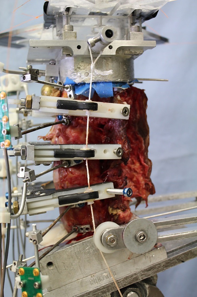
Lumbar spine (L1-5) experimental setup showing compressive follower preload cables and guides.
The angular motion of the L1 to L5 vertebrae were measured using an optoelectronic motion measurement system (Model Certus, Optotrak, Northern Digital, Waterloo, Ontario). In addition, bi-axial angle sensors (Model 902-45, Applied Geomechanics, Santa Cruz, California) were mounted on each vertebra to allow real-time feedback for the optimization of the preload path. A 6-component load cell (Model MC3A-6-1000, AMTI Multi-component transducers, AMTI Inc, Newton, Massachusetts) was placed under the specimen to measure the applied compressive preload and moments. Fluoroscopic imaging (GE OEC 9800 Plus digital fluoroscopy machine) was used to document intact disc heights and implant placement.
Experimental Protocol
Each specimen was tested in flexion (8 Nm) and extension (6 Nm) under 400 N of follower preload as well as without preload.14–18 Each specimen was also tested in lateral bending (±6 Nm) and axial rotation (±5 Nm) without preload. Specimens were tested under the following sequential conditions (Figure 2):
Figure 2.
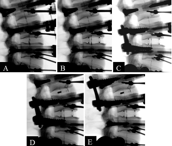
Fluoroscopic images of protocol steps: (A) Intact spine. (B) Standalone anterior lumbar interbody fusion. (C) Anterior lumbar interbody fusion + bilateral pedicle screws. (D) Standalone expandable transforaminal lumbar interbody fusion. (E) Expandable transforaminal lumbar interbody fusion + bilateral pedicle screws.
-
(1)
Intact spine,
-
(2)
Standalone ALIF cage (at L3-4 for specimens 1–6, at L2-3 for specimens 7–12),
-
(3)
ALIF cage + bilateral pedicle screws (at L3-4 for specimens 1–6, at L2-3 for specimens 7–12).
-
(4)
Standalone Luna TLIF cage inserted transforaminally and expanded in situ (at L2-3 for specimens 1–6, at L3-4 for specimens 7–12; Figure 3),
-
(5)
Luna TLIF cage + bilateral pedicle screws (at L2-3 for specimens 1–6, at L3-4 for specimens 7–12).
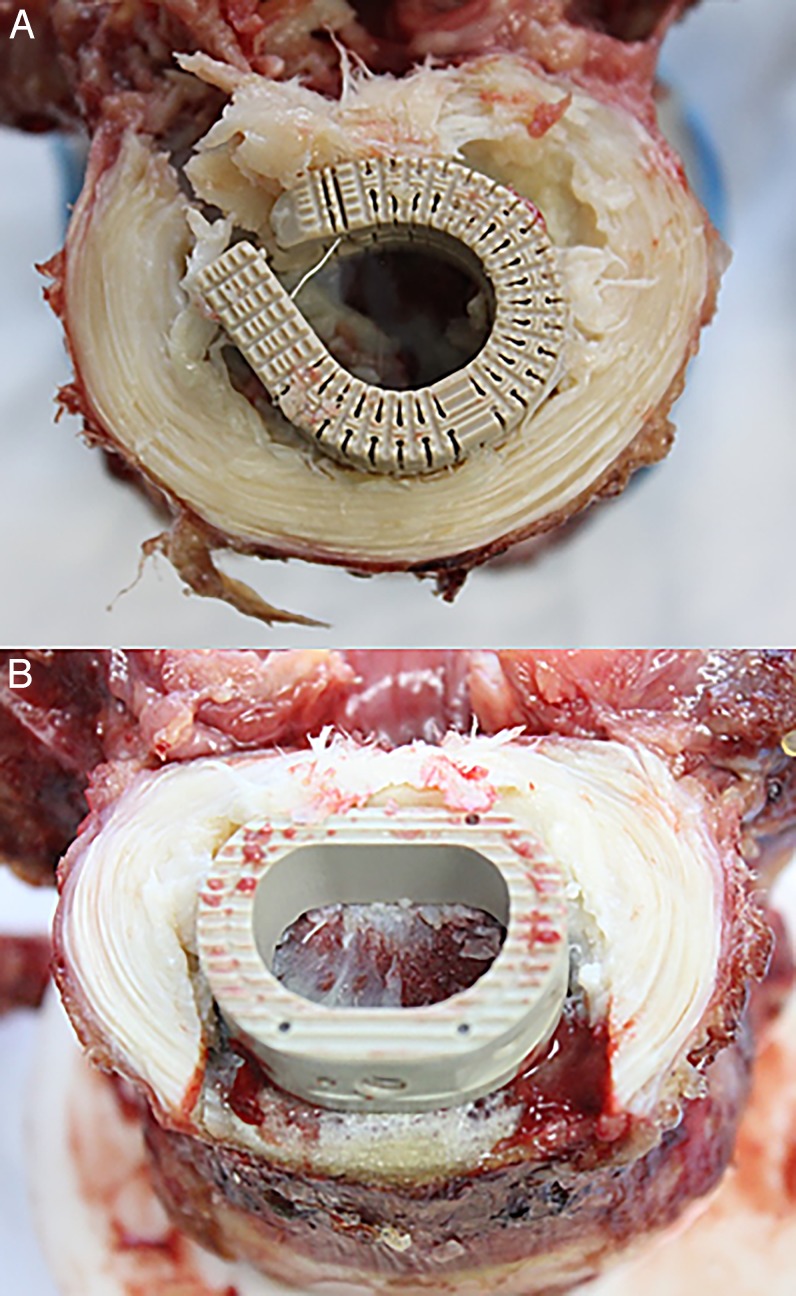
Figure 3.
View of inferior endplates and implant placements after sectioning of intervertebral disc. (A) Expandable transforaminal lumbar interbody fusion cage showing the posterior approach. (B) Anterior lumbar interbody fusion cage showing the anterior approach.
Thus, 12 segments were implanted with control ALIF cages, 6 at L2-3 and 6 at L3-4. Similarly, 12 segments were implanted with deployable and expandable cages, 6 at L2-3 and 6 at L3-4.
Surgical Technique
The ALIF “control” cage was implanted according to company surgical technique guidelines. A window matching the cage width was made in the anterior annulus and anterior longitudinal ligament. Disc material was removed, and the vertebral endplates were prepared in a conventional fashion while preserving their mechanical integrity. Trial sizing aided by fluoroscopy was performed to select the proper cage size.
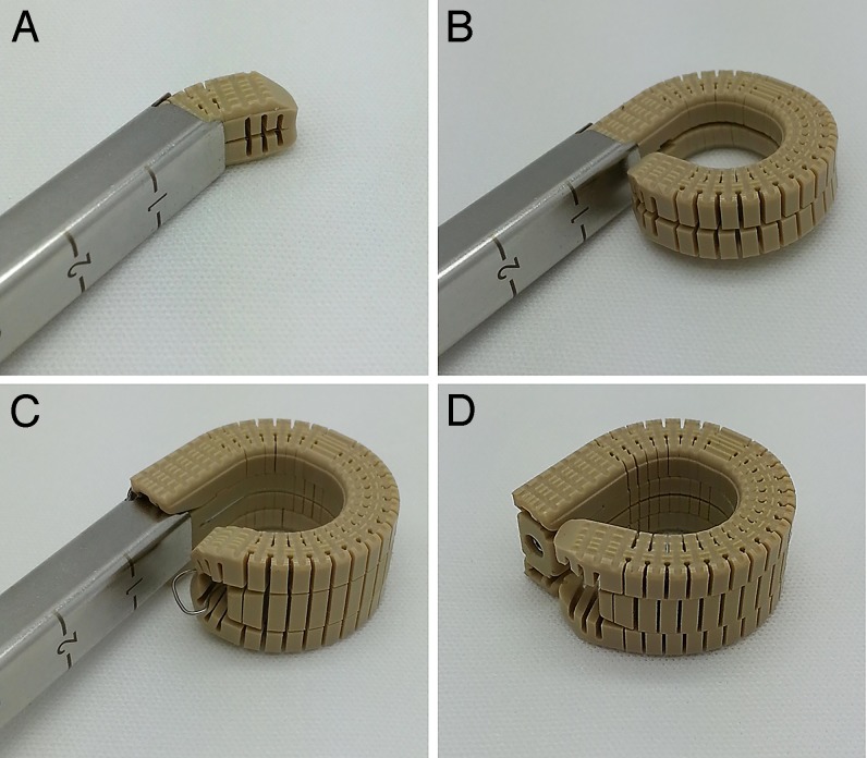
Implantation of a deployable and expandable lumbar interbody fusion device (Luna 360, Benvenue Medical, Inc) was performed using the standard transforaminal approach. A small window was made in the posterolateral annulus. Disc material was removed to allow sufficient room for the device to be deployed. The device was then deployed in situ to produce its axial footprint, and finally expanded, effectively distracting the intervertebral disc space (Figure 4). Once deployed, the implant presents a graft window that allows bone graft material to be inserted postexpansion; however, no bone graft material was used for this biomechanical assessment.
Figure 4.
Expandable transforaminal lumbar interbody fusion cage surgical stages. (A) Interbody cage during deployment. (B) Cage fully deployed. (C) Cage expanded. (D) Final step.
Statistical Analysis
The applied moment versus vertebral motion data were analyzed using standard methods of rigid body kinematics.19 Segmental ranges of motion values were analyzed using paired-sample t tests. The following comparisons were made:
-
(a)
Combined control cage (n = 12) versus dombined deployable and expandable cage (n = 12),
-
(b)
Combined control cage + pedicle screws (PS) (n = 12) versus combined deployable and expandable cage + PS (n = 12).
These comparisons were done separately for flexion-extension, lateral bending, and axial rotation, since no comparisons across load types were intended in the study design. The statistical data analyses were performed with use of the Systat 10.2 software package (Systat Software, Richmond, California).
RESULTS
When used as a standalone device, the deployable and expandable TLIF cage significantly reduced motion in flexion-extension, from 7.1 ± 1.1 to 3.3 ± 1.3° under no preload, P < .01, and from 7.1 ± 1.1 to 3.1 ±1.1° under 400 N preload, P < .01 (Table 1). This represents a decrease in sagittal plane motion by 53 and 57%, respectively. The control cage also significantly reduced flexion-extension motion from 7.4 ± 1.8 to 5.2 ± 1.4° under no preload, P < .01, and from 7.4 ± 1.6 to 2.9 ± 0.8° under 400 N preload, P < .01 (Table 2). This represents a decrease in sagittal plane motion by 28 and 61%, respectively (Figures 5 and 6). The difference in the abilities of the deployable and expandable cages and control devices in limiting flexion-extension motion under the preload of 400 N was statistically equivalent (57 versus 61%, P = .31). However, in the absence of compressive preload, the deployable and expandable TLIF cage was superior in limiting flexion-extension motion (53 versus 28%, P = .00).
Table 1.
Segmental range of motion* (mean ± SD) with (experimental) transforaminal lumbar interbody fusion (TLIF) cage (°).
|
Intact |
TLIF |
TLIF + PS |
% Change TLIF from Intact |
% Change TLIF + PS from Intact |
|
| Flexion-extension 0 N | 7.1 ± 1.1 | 3.3 ± 1.3 | 0.6 ± 0.3 | −53 ± 18% | −91 ± 3.9% |
| Flexion-extension 400 N | 7.1 ± 1.1 | 3.1 ± 1.1 | 0.6 ± 0.2 | −57 ± 14% | −91 ± 3.5% |
| Lateral bending | 8.0 ± 1.5 | 4.1 ± 1.5 | 1.1 ± 0.4 | −50 ± 16% | −86 ± 4.5% |
| Axial rotation | 2.4 ± 1.4 | 1.5 ± 0.5 | 0.7 ± 0.2 | −21 ± 40% | −62 ± 24% |
Abbreviation: PS, pedicle screws.
Reported ranges of motion are from combined L2–L3 and L3–L4 motion data.
Table 2.
Segmental range of motion* (mean ± SD) with (control) anterior lumbar interbody fusion (ALIF) cage (°).
|
Intact |
ALIF |
ALIF + PS |
% Change ALIF from Intact |
% Change ALIF + PS from Intact |
|
| Flexion-extension 0 N | 7.4 ± 1.8 | 5.2 ± 1.4 | 0.8 ± 0.3 | −28 ± 15% | −89 ± 4.7% |
| Flexion-extension 400 N | 7.4 ± 1.6 | 2.9 ± 0.8 | 0.6 ± 0.1 | −61 ± 12% | −92 ± 1.9% |
| Lateral bending | 8.9 ± 1.9 | 3.9 ± 1.7 | 1.1 ± 0.4 | −56 ± 14% | −88 ± 3.4% |
| Axial rotation | 2.6 ± 2.1 | 1.6 ± 0.9 | 0.6 ± 0.3 | −22 ± 36% | −66 ± 22% |
Abbreviation: PS, pedicle screws.
Reported ranges of motion are from combined L2–L3 and L3–L4 motion data.
Figure 5.
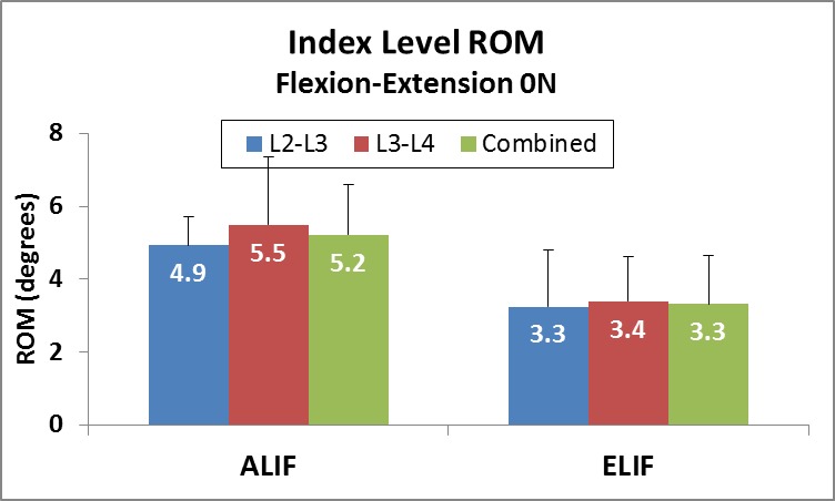
Range of motion (ROM) of anterior lumbar interbody fusion (ALIF) and the expandable transforaminal lumbar interbody fusion (ELIF) devices in both implanted segments (L2-3 and L3-4) in flexion-extension without preload.
Figure 6.
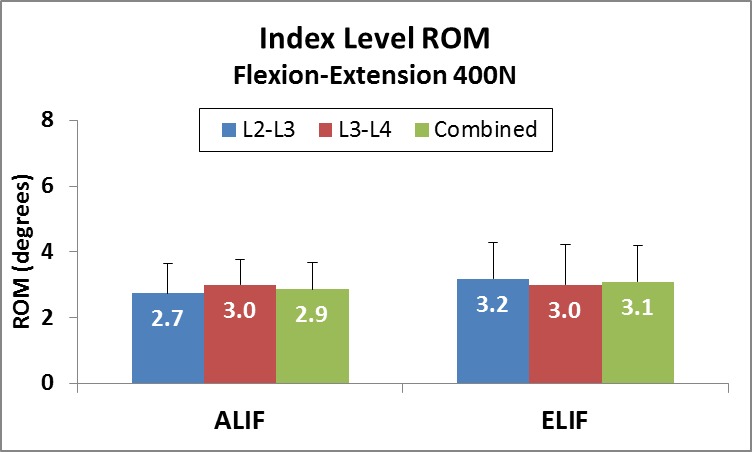
Range of motion (ROM) of anterior lumbar interbody fusion (ALIF) and the expandable transforaminal lumbar interbody fusion (ELIF) devices in both implanted segments (L2-3 and L3-4) in flexion-extension under 400 N follower preload.
In lateral bending, the deployable and expandable TLIF cage reduced motion from 8.0 ± 1.5 to 4.1 ± 1.5°, P < .01. This represents a decrease in coronal plane motion of 50%. The control cage reduced motion from 8.9 ± 1.9 to 3.9 ± 1.7°, P < .01. This represents a reduction of coronal plane motion of 56.4% (Tables 1 and 2, Figure 7). There was no statistically significant difference in the abilities of the deployable and expandable cages and control devices in limiting lateral bending motion (50 versus 56%, P = .26).
Figure 7.
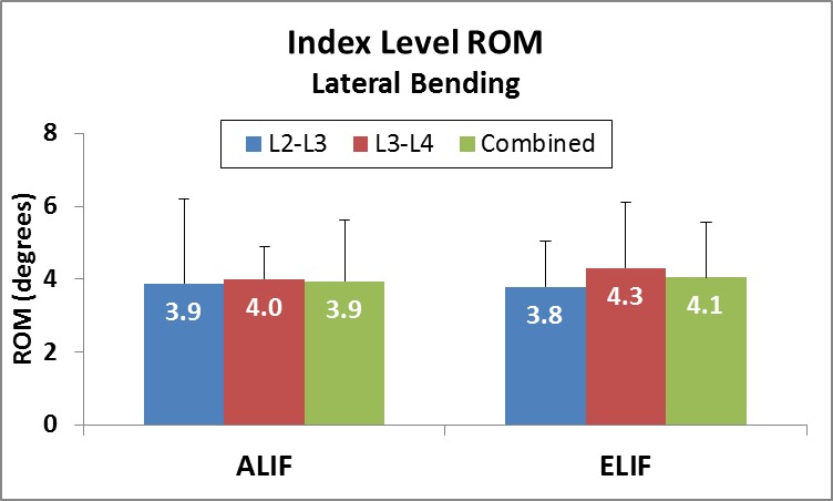
Range of motion (ROM) of anterior lumbar interbody fusion (ALIF) and expandable transforaminal lumbar interbody fusion (ELIF) devices in both implanted segments (L2-3 and L3-4) in lateral bending.
In axial rotation, the deployable and expandable TLIF cage reduced range of motion from 2.4 ± 1.4 to 1.5 ± 0.5°, P < .05. This represents reduced motion in the axial plane by 21%. The ALIF control cage reduced motion from 2.6 ± 2.1 to 1.6 ± 0.9°, P < .05. This represents reduced motion in the axial plane of 22% (Tables 1 and 2, Figure 8). The difference in the abilities of the deployable and expandable cages and control devices in limiting axial rotation motion was statistically equivalent (21 versus 22%, P = .94).
Figure 8.
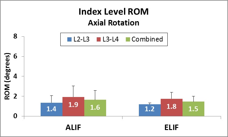
Range of motion (ROM) of anterior lumbar interbody fusion (ALIF) and expandable transforaminal lumbar interbody fusion (ELIF) devices in both implanted segments (L2-3 and L3-4) in axial rotation.
Supplemental posterior fixation using bilateral pedicle screws and rods resulted in further reduction in range of motion in flexion-extension, lateral bending, and axial rotation (Tables 1 and 2). The effect of supplemental fixation was significant compared to the standalone devices, for both TLIF and ALIF cages (P < .01). Both devices, when used in conjunction with supplemental fixation, were statistically equivalent in their ability to reduce segmental motion in flexion-extension (P > .22), lateral bending (P = .06), and axial rotation (P = .61).
DISCUSSION
This study compared the relative biomechanical stability between 2 implants of similar footprint size inserted using 2 different surgical approaches.2,3 The shape and size of the fully deployed and expanded TLIF cage is very similar to a traditional ALIF cage. Despite the fact that the anterior longitudinal ligament is removed during ALIF insertion, we chose not to compare to a traditional TLIF cage since the endplate coverage is much smaller than the deployable and expandable Luna cage. Therefore, both deployable and expandable TLIF and ALIF cages provide similar surface area for bone graft material, increased stiffness imparted by anterior column support, and the ability to restore sagittal alignment.
Lumbar interbody fusion using a fusion cage with bone graft has benefits when compared to a posterolateral fusion technique. The benefits include greater surface area for bone graft-endplate interface, increased stiffness due to anterior column support,1 and the ability to restore alignment. Circumferential constructs consisting of an anterior cage and posterior instrumentation have been shown to improve fusion rates.20 A number of interbody techniques have been described including ALIF, PLIF, and TLIF, each with its own respective advantages and disadvantages.1–3 Posterior interbody fusion techniques when used in circumferential fusions have the advantage of a single approach.1–3 However, the anatomy limits the size of the interbody device that can be inserted posteriorly. The anterior approach affords a larger implant footprint given the unencumbered path to the disk space. Grant and colleagues demonstrated that lumbar endplate density and cortical thickness increase as one approaches the periphery of the vertebral body which makes placement of a cage with larger surface area desirable.21
A deployable and expandable lumbar interbody fusion cage which allows for a single, minimally invasive, posterior approach and annulotomy with intervertebral deployment resulting in a broad-based footprint may improve outcomes and limit complication. The purpose of this study was to demonstrate biomechanical equivalency of this type of a device to a standard ALIF cage. The biomechanical stability of the deployable and expandable TLIF cage was found to be at least equivalent to the ALIF cage, both when used as standalone devices as well as when supplemented with bilateral pedicle screw-rod stabilization. Although neither implant is intended to be used as a standalone device, both implant types were tested as such in order to elucidate the stability imparted by the interbody device itself, independent of the posterior instrumentation. The in situ expandable nature of the cage after implantation allows for distraction of the disc space without violating endplates during insertion for the same cage size.
The 2 devices significantly reduced segmental motion at the level of implantation, and no statistical difference between the devices in reducing flexion-extension with compressive preload, lateral bending, or axial rotation was observed. Under flexion-extension testing without preload, there was a statistically significant difference between the 2 devices favoring increased stability of the deployable and expandable TLIF cage. This is attributable to the retention of the anterior tension band and a small annular window of the TLIF approach through which the deployable and expandable device can be inserted prior to in situ expansion.
The compressive preload in the lumbar spine is caused by the action of muscles and has been shown to vary from a low value of 200 N during supine and lateral recumbent postures to over 1000 N during standing and walking.22 Therefore, the improved stability of the standalone deployable and expandable TLIF cage construct compared to the standalone ALIF cage construct in the absence of a compressive preload may offer improved protection against migration during the low preload activities.
LIMITATIONS
As any cadaveric biomechanical investigation, our study has limitations. We compensated for the absence of active muscles by using follower preload.6–9 In this study, our implantation levels of L2-3 and L3-4 were chosen in order to have similar anatomy (wedge angle, facet angulation) and kinematics at the 2 implanted levels. Using L4-5 would have been more clinically relevant, but the lordosis and range of motion at L4-5 is significantly different than at L3-4.
CONCLUSIONS
The deployable and expandable Luna cage that can be inserted through the TLIF approach with a small annular window and expanded axially in situ has the advantages of a single posterior approach and broad endplate footprint while retaining the anterior tension band for added stability. When compared to an ALIF cage, the deployable and expandable TLIF cage demonstrates biomechanical equivalence in regard to segmental stability in the coronal, sagittal, and axial planes. The effect of this on fusion rate and decreased complications needs to be clinically studied.
The deployable and expandable TLIF cage is an improvement over traditional fixed-dimension TLIF cages due to the implant's deployment technology, making implantation possible through a narrow surgical corridor, resulting in minimal nerve root retraction and tissue dissection. Additional benefits over traditional TLIF designs include a much larger endplate footprint and the ability to axially expand the device to add annular tension and segmental lordosis.
Acknowledgments:
Acknowledgments: Supported by the Department of Veterans Affairs, Washington, DC, and Benvenue Medical, Santa Clara, CA.
REFERENCES
- 1.Lee CS, Hwang CJ, Lee DH, et al. Fusion rates of instrumented lumbar spinal arthrodesis according to surgical approach: a systematic review of randomized trials. Clin Orthop Surg. 2011;3(1):39–47. doi: 10.4055/cios.2011.3.1.39. [DOI] [PMC free article] [PubMed] [Google Scholar]
- 2.Pannell WC, Savin DD, Scott TP, Wang JC, Daubs MD. Trends in the surgical treatment of lumbar spine disease in the United States. Spine J. 2015 Aug 1;15(8):1719–1727. doi: 10.1016/j.spinee.2013.10.014. [DOI] [PubMed] [Google Scholar]
- 3.Talia AJ, Wong ML, Lau HC, Kaye AH. Comparison of the different surgical approaches for lumbar interbody fusion. J Clin Neurosci. 2015;22(2):243–251. doi: 10.1016/j.jocn.2014.08.008. [DOI] [PubMed] [Google Scholar]
- 4.Mobbs RJ, Loganathan A, Yeung V, Rao PJ. Indications for anterior lumbar interbody fusion. Orthop Surg. 2013;5(3):153–163. doi: 10.1111/os.12048. [DOI] [PMC free article] [PubMed] [Google Scholar]
- 5.Ahmadian A, Verma S, Mundis GM, Jr, Oskouian RJ, Jr, Smith DA, Uribe JS. Minimally invasive lateral retroperitoneal transpsoas interbody fusion for L4–5 spondylolisthesis: clinical outcomes. J Neurosurg Spine. 2013;19(3):314–320. doi: 10.3171/2013.6.SPINE1340. [DOI] [PubMed] [Google Scholar]
- 6.Billinghurst J, Akbarnia BA. Extreme lateral interbody fusion—XLIF. Curr Orthop Pract. 2009;20(3):238–521. [Google Scholar]
- 7.Harris BM, Hilibrand AS, Savas PE, et al. Transforaminal lumbar interbody fusion: the effect of various instrumentation techniques on the flexibility of the lumbar spine. Spine (Phila Pa 1976) 2004;29(4):E65–E70. doi: 10.1097/01.brs.0000113034.74567.86. [DOI] [PubMed] [Google Scholar]
- 8.Phillips FM, Isaacs RE, Rodgers WB, et al. Adult degenerative scoliosis treated with XLIF: clinical and radiographical results of a prospective multicenter study with 24-month follow-up. Spine (Phila Pa 1976) 2013;38(12):1853–1861. doi: 10.1097/BRS.0b013e3182a43f0b. [DOI] [PubMed] [Google Scholar]
- 9.Pimenta L, Turner AW, Dooley ZA, Parikh RD, Peterson MD. Biomechanics of lateral interbody spacers: going wider for going stiffer. ScientificWorld J. 20122012 doi: 10.1100/2012/381814. :381814. [DOI] [PMC free article] [PubMed]
- 10.Schwender JD, Holly LT, Rouben DP, Foley KT. Minimally invasive transforaminal lumbar interbody fusion (TLIF): technical feasibility and initial results. J Spinal Disord Tech. 2005;18(suppl 1):S1–S6. doi: 10.1097/01.bsd.0000132291.50455.d0. [DOI] [PubMed] [Google Scholar]
- 11.Cannestra AF, Peterson MD, Parker SR, Roush TF, Bundy JV, Turner AW. MIS expandable interbody spacers: a literature review and biomechanical comparison of an expandable MIS TLIF with conventional TLIF and ALIF. Spine (Phila Pa 1976) 2016;41(Suppl 8):S44–S49. doi: 10.1097/BRS.0000000000001465. [DOI] [PubMed] [Google Scholar]
- 12.Kunz D, Zdeblick T, McCabe R, et al. The effect of the mechanical environment on healing of a lumbar fusion using an in vivo model. 42nd Annual Meeting Orthopaedic Research Society, February 18–22, 1996, Atlanta, Georgia.
- 13.Perrin A, Cordey J. The concept of interfragmentary strain. 1980. In. Uhtoff HK, ed. Current Concepts of Internal Fixation of Fractures Berlin: Springer-Verlag.
- 14.Patwardhan AG, Havey RM, Meade KP, Lee B, Dunlap B. A follower load increases the load carrying capacity of the lumbar spine in compression. Spine (Phila PA 1976) 1999;24(10):1003–1009. doi: 10.1097/00007632-199905150-00014. [DOI] [PubMed] [Google Scholar]
- 15.Patwardhan AG, Carandang G, Ghanayem A, et al. Compressive preload improves the stability of the anterior lumbar interbody fusion (ALIF) cage construct. J Bone Joint Surg (Am). 2003;85-A(9):1749–1756. doi: 10.2106/00004623-200309000-00014. [DOI] [PubMed] [Google Scholar]
- 16.Phillips FM, Cunningham B, Carandang G, et al. Effect of supplemental translaminar facet screw fixation on the stability of stand-alone ALIF cages under physiologic loads. Spine (Phila Pa 1976) 2004;29(16):1731–1736. doi: 10.1097/01.brs.0000134570.08901.30. [DOI] [PubMed] [Google Scholar]
- 17.Tzermiadianos MN, Mekhail A, Voronov LI, et al. Enhancing the stability of anterior lumbar interbody fusion: a biomechanical comparison of anterior plate versus posterior transpedicular instrumentation. Spine (Phila Pa 1976) 2008;33(2):E38–E43. doi: 10.1097/BRS.0b013e3181604644. [DOI] [PubMed] [Google Scholar]
- 18.Goel VK, Panjabi MM, Patwardhan AG, Dooris AP, Serhan H. Test protocols for evaluation of spinal implants. J Bone Joint Surg. 2006;88-A(Suppl 2):103–109. doi: 10.2106/JBJS.E.01363. [DOI] [PubMed] [Google Scholar]
- 19.Suh CH, Radcliffe CW. Kinematics and Mechanisms Design. Malabar, FL: Krieger Publishing Company; 1983. [Google Scholar]
- 20.Fritzell P, Hagg O, Wessberg P, Nordwall A. Swedish Lumbar Spine Study G. Chronic low back pain and fusion: a comparison of three surgical techniques: a prospective multicenter randomized study from the Swedish lumbar spine study group. Spine (Phila Pa 1976) 2002;27(11):1131–1141. doi: 10.1097/00007632-200206010-00002. [DOI] [PubMed] [Google Scholar]
- 21.Grant JP, Oxland TR, Dvorak MF. Mapping the structural properties of the lumbosacral vertebral endplates. Spine (Phila Pa 1976) 2001;26(8):889–896. doi: 10.1097/00007632-200104150-00012. [DOI] [PubMed] [Google Scholar]
- 22.Nachemson A. Lumbar intradiscal pressure. Experimental studies on post-mortem material. Acta Orthop Scand Suppl. 1960;43:1–104. doi: 10.3109/ort.1960.31.suppl-43.01. [DOI] [PubMed] [Google Scholar]


