

Abstract
Fine needle deflection is a problem encountered during insertion into a soft tissue. Although an axial rotational insertion is an effective approach for minimizing this problem, needle deflection still depends on the insertion angle with respect to the tissue boundary. Since the human body consists of multi-layered tissues of various shapes and mechanical properties, preoperative planning of an optimal path is a key factor for achieving a successful insertion. In this paper, we propose an optimization-based preoperative path planning model that minimizes needle deflection during multi-layered tissue insertion. This model can determine the optimal path based on the sum of insertion angles with respect to each tissue boundary that the needle passes through. To increase the accuracy of the model, we incorporated the effect of distances from tissue boundaries and the probability that the deflection is acceptable by incorporating weighting factors into the model. To validate the model, we performed experiments involving four scenarios of two- and three-layered tissues. The results showed that the proposed model is capable of determining the optimal insertion path in all scenarios.
Index Terms: Needle insertion, Path planning
I. Introduction
RECENTLY, percutaneous needle insertion has become a common procedure in place of open surgery, particularly for biopsies of abdominal tumors, breast cancer, and prostate cancer [1]. Tissue damage, risks of complications, and patient trauma can be reduced significantly by using a fine needle of thinner than 25 gauge or thinner. Meanwhile, it is difficult to insert the fine needle into a target because the needle is deflected easily. In particular, the procedure in which the needle needs to pass through multi-layered tissues, such as the lower abdomen, requires proficient skills because of complex deflections that often occur. There have been many studies aiming to assist percutaneous needle insertion using robotic systems for targeting the prostate, liver, and breast [2–4]. However, there are few studies focusing on multi-layered tissues, such as the lower abdomen. In the case of needle insertion into multi-layered tissues, CT (Computerized Tomography) and MRI (Magnetic Resonance Imaging) are typically used as medical image guidance modalities for making a preoperative insertion path plan and placing the needle tip in the proper anatomical position during insertion. Both imaging modalities can provide high-resolution and low-noise images compared to ultrasound imaging. In particular, it is difficult to apply ultrasound imaging to an area containing air, such as the intestine and lungs. Meanwhile, with both, CTs and MRIs, it is difficult to track the needle and target position in real time as is the case for ultrasound imaging. Continuous CT scans could provide real time needle tip positioning information, but the patient’s radiation exposure is increased. MRIs typically require longer times for a single scan compared to a CT scan. Therefore, a preoperative insertion path plan based on CT and/or MRI imaging, which determines an accurate path for the needle tip to reach the appropriate target, has a benefit in cases involving multi-layered tissues.
Needle steering, a needle insertion technique that controls the needle trajectory by rotating a bevel-tipped flexible needle, has been widely studied by many researchers [5]. The benefit of needle steering is to efficiently avoid anatomical obstacles, such as bones and sensitive structures (blood vessels or nerves). Meanwhile, applying needle steering to these cases is challenging because there is less feedback information with CTs and MRIs. Needle steering could be controlled by closed-loop planning coupled with ultrasound imaging [6]. Although some researchers have proposed deflection models for open-loop steering [7–9], it is challenging to accurately estimate the needle tip deflection because the multi-layered tissue is composed of several layers with different mechanical properties, causing complex deflection patterns. To estimate the real time needle shape during insertion, fiber Bragg grating (FBG) sensors are often used. However, there are still some problems embedding the sensors into fine needles, in addition to increased complexity of the system setup and the system cost [10]. Although an electromagnetic position tracking sensor can visualize needle shapes, the accuracy is uncertain because of possible ferrous materials in the sensor workspace. It is difficult to embed the sensor into fine needles [11].
Previously, we proposed an approach that facilitates the straight insertion of the fine needle by minimizing needle tip deflection [12–13]. As an insertion method for minimizing needle tip deflection and targeting errors, needle insertion with axial rotation is a common approach [14–16]. We showed that needle insertion with a bidirectional rotation, which involves switching the rotational direction 360° clockwise and counter-clockwise, can minimize both the needle deflection and tissue damage [17]. However, in our previous work, we also found that some deflection still occurs even when using the bidirectional rotational insertion method when the needle is inserted at an angle to the tissue surface, even though there is less deflection when inserting the needle perpendicularly to the tissue surface [13]. Additionally, in order to minimize the needle deflection when using an axial rotational insertion, a preoperative plan that considers the insertion angle is necessary.
In this paper, we developed a preoperative needle insertion path plan for minimizing needle deflection during insertion into multi-layered tissues. The main contribution of this paper is a novel optimization-based preoperative path planning model for percutaneous needle insertion into multi-layered tissue. It accounts for needle deflections occurring as a result of insertion angles at each tissue boundary that the needle passes thorough. As a practical advantage of the proposed method, it is expected to reduce sensing cost during needle insertions such as mostly radiation dose for CT because of minimizing the number of shots.
II. Preoperative Insertion Path Planning
A. Concept of Insertion Path Planning
In this section, we describe the planning method for the automatic definition of optimal needle insertion positions and angles for minimizing the needle tip deflection using an insertion with axial rotation. For an ideal tissue layer where the needle is aligned with the target, as shown in Fig. 1 (a), the optimal insertion path can be determined to pass through each boundary vertically. Meanwhile, in the case of a real tissue layer that is aligned at a random angle, as shown in Fig. 1 (b), it is necessary to consider each angle between the insertion path direction and the tissue boundaries in order to decide the optimal insertion path. This is because these angles may cause substantial deflections according to our previous research [13].
Fig. 1.

(a) Ideal insertion case of multi-layered tissue (b) complex insertion case of multi-layered tissue (c) definition of insertion angle
To determine the optimal insertion path in a complex situation, we assume that the needle deflection can be minimized when the sum of each angle between the tissue boundary (or surface) and the insertion direction on a selected insertion path is minimized. By minimizing the sum of all the angles, this is expected to cancel out the effect of deflection in each tissue layer during insertion. In addition, some factors cause deflection, such as tissue stiffness, non-homogeneity, and insertion distance. In order to account for those effects, a weighting factor is assigned to each angle. The proposed objective function f is defined as follows:
| (1) |
θi represents the inter-vector angle between the normal vector to the tissue boundary and insertion direction vector at which the needle will contact the i-th tissue boundary, which is shown in Fig. 1 (c). Furthermore, wi represents the weighting factor at that time. Finally, n is the total number of layers that make up the multi-layered tissue. For example, in the case of the three-layered tissue shown in Fig. 1 (b), θ1, θ2, and θ3 represent the inter-vector angles at the surface of tissue A, the boundary between tissue A and B, and the boundary between tissue B and C, respectively. Those inter-vector angles change depending on the initial insertion position and selected angle. The optimal position and angle can be determined by minimizing this objective function. In the following sections, we will describe how to determine the weighting factors for increasing targeting accuracy.
B. Tissue Boundary Distance
As one of the factors for causing a large deflection, the effect of the tissue boundary distance needs to be accounted for in the weighting factor. According to the previous research, the deflection was increased almost linearly depending on insertion depths [15]. Then, once deflection occurs at the tissue boundary, we assume that the final deflection differs depending on the distance between the tissue boundary and the target. For example, we compare two situations consisting of two-layered tissues with different boundary distances (Li). These tissues are composed of layers with the same angles and tissue properties shown in Fig. 2. The final deflection is linearly decreased as the difference between Li and the total insertion distance from an initial position to the target (Ltar) is decreased. This is the case if both deflection slopes in Fig. 2 can be approximated as almost equal. Thus, we define the effect of boundary distance as the following weight factor:
| (2) |
Fig. 2.

Comparison of two-layered tissue with different boundary distance. A final deflection will be large (a) if the boundary is closed to the surface, and be small (b) if the boundary is far from the surface.
C. Deflection Probability
The deflection also differs as a result of the mechanical properties of the tissues, such as stiffness, viscoelasticity, and inhomogeneity. Although many researchers have focused on developing needle deflection models, there are no models that consider the effect of insertion angle between the tissue boundary and the insertion direction. According to our previous study, the main reason for increasing the deflection as a result of the insertion angle may be initial tissue deformation before puncturing the boundary [13]. Meanwhile, it has been reported that the analysis of the puncture phenomenon is still a challenging problem because this phenomenon varies even if the same insertion force and insertion distance are applied [18]. In addition, the puncture phenomenon may be more complex when inserting a needle using axial rotation with respect to the angle of the tissue boundary. Thus, it does not seem realistic to estimate deflection considering those uncertain factors. Therefore, instead of estimating the deflection value deterministically, we consider the probability that the deflection occurs as a result of the insertion angle and mechanical properties of the tissues. By considering the probability, the effect of those uncertain factors, which are difficult to be included as deterministic parameters, can be effectively captured in the path planning.
As shown in Fig. 3 (a), deflection occurs with some variability, and an acceptable deflection depends on the boundary distance (Li) and target size (rtar). We assume that the deflection slope (φi) is approximately constant after puncturing the boundary because the main reason for deflection relates to the insertion angle and the initial tissue deformation such that the needle is inserted straight as a result of axial rotation after puncturing the boundary. We define the probability that the variable deflection slope (φi) is within the acceptable deflection slope (Φi) as deflection probability. In order to obtain the deflection probability, it is necessary to model a probability distribution for deflection occurrence at arbitrary insertion angles in each layer of a multi-layered tissue. By collecting deflection slope data at several insertion angles with each tissue type, we can generalize the probability distribution of deflection occurrences and define it as deflection probability distribution. The deflection probability can be expressed as a cumulative distribution function of the deflection probability distribution as follows:
| (3) |
where p(θi) is the deflection probability, φi is the deflection slope of the insertion angle at θi, Φi is acceptable deflection slope, and is the deflection probability distribution (Fig. 3 (b)). We assume that the deflection probability distribution is derived from fitting experimental data to the Gaussian distribution model because the Gaussian distribution model is a standard method and it can be expressed with only two parameters. The deflection probability distribution can be expressed as follows:
| (4) |
where μθi and σθi are the mean and standard deviation of the deflection-slope at the insertion angle at θi, respectively. By fitting those two parameters at arbitrary insertion angles from the experimental data (see Section III-B), the deflection probability distribution can be generalized using the Gaussian distribution model. With the Gaussian distribution model generalized in each layer of a multi-layered tissue, Eq. (3) of the deflection probability in each tissue can be replaced with Eq. (4) as follows:
| (5) |
Fig. 3.

(a) Illustration of the probability that the deflection occurrence due to the insertion angle is within the acceptable deflection (blue area) (b) Example of calculated deflection probability (orange line) and deflection probability distribution (blue line) to deflection slope φi in an insertion angle at θi.
The deflection probability means that the probability that the value for the deflection occurrence is within acceptable ranges. In short, the probability approaches approximately 100% when the insertion angle approaches 0°. Since the score of the objective function should be small as each insertion angle decreases, we define the effect of deflection probability as an additional weight factor as follows:
| (6) |
Therefore, combining the weight factors from Eq. (2) and (6), the objective function of Eq. (1) is defined as follows:
| (7) |
III. Evaluation
In this section, we first present the experiment to fit the deflection probability. Next, the proposed path planning with the fitted deflection probability is verified.
A. Experimental Setup
The experimental setup used to insert fine needles into several soft tissues and biological tissue phantoms for measuring needle tip deflections is shown in Fig. 4. The setup is composed of two parts: 1) a needle driver that has two degrees of freedom (DOF) for translation and rotation about the insertion axis [19] and 2) a Cartesian stage that has three DOFs for positioning the needle driver. A Flea2 FireWire 1394b CCD camera (FLIR Inc., Oregon, USA) is mounted above the setup for measuring needle tip position. The needle conditions are: material, stainless steel 304 (E = 197 GPa); diameter, 25-gauge (φ 0.53 mm); length, 120 mm. The needle tip is beveled at 30°.
Fig. 4.

Experimental setup is composed of 2-DOF needle driver [19] (insertion and rotation axes), Cartesian stage and tissue phantom.
B. Fitting Deflection Probability
As mentioned in Section II-C, experimental data are used to generalize the deflection probability distribution to fit a Gaussian distribution model and derive the deflection probability. In this experiment, Polyvinyl chloride (PVC) is used as a soft tissue phantom, and fresh chicken meat is used as biological tissue. The PVC is made of mixing Super Soft Plastic and softener (M-F manufacturing, Texas, USA), and the phantom stiffness can be changed by altering the ratio of plastic to softener. We prepare two-way stiffness phantoms as follows: 75% of the plastic volume to 25% of the softener volume (E = 150 kPa), 50% of the plastic volume to 50% of the softener volume (E = 100 kPa) [20]. In order to mimic the membrane-like properties of biological tissues, 0.03-mm thick rubber sheets (McMaster-Carr, Illinois, USA) are attached to the PVC surface with staples as shown in Fig. 5 (a). The sizes of PVC phantoms and biological tissues are 150 × 250 × 30 mm3 and 90 × 120 × 30 mm3, respectively. Both tissues are contained in a plastic case (150 × 250 × 50 mm3). Both sides and the back of the biological tissue are fixed with PVC as shown in Fig. 5 (b). In all experiments, the needle is inserted 100 mm into the tissues at an insertion speed of 2 mm/s, and rotational speed is set at 10 rpm (all parameters are set at the maximum value of the current setup). The rotational direction is alternated 360° clockwise and counter-clockwise to avoid winding up tissues [17]. We perform needle insertion at one of five initial insertion angles (0°, 10°, 20°, 30°, or 40°) for all tissues by rotating the phantom case based on baselines. The deflection-slope is calculated with respect to the arcsine of the insertion distance (100 mm), and the needle tip deflection is measured with the camera as shown in Fig. 5 (c). The number of trials is 12 for all conditions.
Fig. 5.

Experimental overview: (a) PVC experiment (b) biological tissue (chicken) experiment, (c) definition of deflection-slope
Fig. 6 shows the results of the deflection-slope. The mean and standard deviation increase depending on the initial insertion angle in all tissues. The experimental data are fitted to a Gaussian distribution as shown in Fig. 7. The values of parameters μ and σ are used to determine the shape of the Gaussian distribution, and these are listed in Table I. Both parameters increase non-linearly depending on the initial insertion angle. Therefore, in order to generalize parameters μ and σ at arbitrary insertion angles in each tissue, we apply second-order polynomial regression for fitting μ and third-order polynomial regression for fitting σ as shown below:
| (8) |
Fig. 6.
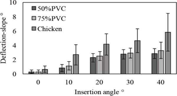
Experimental result of deflection-slope due to insertion angles.
Fig. 7.

Results of fitting experimental deflection data to Gaussian model: (a) PVC50%, (b) PVC75% and (c) chicken.
TABLE I.
Gaussian Distribution Parameters
| Insertion angle ° | 0 | 10 | 20 | 30 | 40 | |
|---|---|---|---|---|---|---|
| PVC50% |
μ σ |
0.296 0.241 |
0.835 0.492 |
2.25 0.593 |
2.75 0.655 |
2.83 0.703 |
| PVC75% |
μ σ |
0.291 0.273 |
1.12 0.593 |
2.49 0.611 |
2.88 0.694 |
3.28 1.13 |
| Chicken |
μ σ |
0.652 0.422 |
2.68 1.40 |
4.12 1.51 |
4.64 1.68 |
5.81 2.64 |
Fig. 8 and Table II show the result of fitting the unknown coefficient a of the polynomial regression model with parameters μ and σ listed in Table I. Notice that all of the determination coefficients (R2) of the regression model in all conditions are close to 1.0. We then use those fitted coefficients from Eq. (8) and apply them to Eq. (5).
Fig. 8.

Results of fitting parameters μ (upper row) and σ (bottom row) of Gaussian model to polynomial regression model: (a) PVC50%, (b) PVC75% and (c) Chicken. Blue dots show the parameters obtained by experimental data, green lines show the estimated parameters and red lines show a confident band of 95%.
TABLE II.
Polynomial Regression Model Coefficient
| Coefficient | a0 | a1 | a2 | a3 | |
|---|---|---|---|---|---|
| PVC50% |
μ σ |
0.133 0.242 |
0.122 0.0332 |
−1.31E-03 −9.91E-04 |
– 1.12E-05 |
| PVC75% |
μ σ |
0.203 0.274 |
0.130 0.0566 |
−1.32E-3 −3.06E-3 |
– 5.46E-5 |
| Chicken |
μ σ |
0.747 0.425 |
0.198 0.165 |
−1.88E-3 −8.28E-3 |
– 1.38E-4 |
C. Verification of Insertion Path Planning
To evaluate the performance of the proposed insertion path plan, we conducted experiments on several of the multi-layered tissues used in Section III-B. In this experiment, we prepared two scenarios consisting of two-layered tissue phantoms and two scenarios consisting of three-layered tissue phantoms. We performed insertions from ten needle entry positions. Angles included approximately −27°, −21°, −15°, −9°, −3°, 3°, 9°, 15°, 21°, and 27° based on a center vertical line to a target. Each of these experiments is shown in Fig. 9. The ten needle entry positions are randomly chosen among the setup limitations. Each insertion angles are measured with lines of tissue boundary and insertion path connecting each needle entry positions and the target, and the objective function of Eq. (1) calculates the score for each needle entry positions with those calculated insertion angles. In order to verify the effect of the weight factor in the objective function, we compared four-way weight factors: (a) the proposed weight factor (wi = wDist × wProb) (b) considering only insertion angle (wi = 1) (c) considering the tissue boundary distance (wi = wDist) (d) considering the deflection probability (wi = wProb). Notice that ptissue(θi) of Eq. (5) is calculated with those measured insertion angles. The minimum score should correspond to the optimal needle entry position. We verified this by comparing the calculated scores and needle tip deflections measured in these experiments. The target size (rtar) is set to ±2 mm in this experiment [12]. Six trials are performed for each entry position for all experimental scenarios. Needle insertion conditions are same as in Section III-B.
Fig. 9.

Experimental scenario overview. Targets are set at (125, 50). Both sides of chicken are fixed with PVC same as Fig. 5 (b)
Fig. 10 shows the results of the needle tip deflection and scores of four-way objective functions. Table III shows the order of the deflection values and scores for all needle entry positions, and the concordance cases of the order are highlighted in all scenarios. Those results show similar relationships among deflections and scores for all entry positions, and the minimum deflection agrees with the minimum scores calculated by all objective functions in all scenarios. The concordance case rates of each objective functions in Scenario I–IV are below: (a) 70% (7/10), 50% (5/10), 40% (4/10), and 60% (6/10), (b) 60% (6/10), 10% (1/10), 40% (4/10), and 40% (4/10), (c) 70% (7/10), 10% (1/10), 40% (4/10), and 50% (5/10) and (d) 60% (6/10), 50% (5/10), 40% (4/10), and 60% (6/10) (as shown in Table III).
Fig. 10.

Comparison of scores calculated with the objective function and needle tip deflections in all needle entry positions. Red line, blue line, green line and gray line show the condition of (a) the proposed weight factor, (b) considering only insertion angle, (c) considering the tissue boundary distance and (d) considering the deflection probability
TABLE III.
Order Of Deflection And Score In All Entry Position
| Scenario I | |||||||||||
| Needle entry positions | 1 | 2 | 3 | 4 | 5 | 6 | 7 | 8 | 9 | 10 | |
| Deflection | 10 | 9 | 7 | 6 | 2 | 1 | 3 | 4 | 5 | 8 | |
| Score | (a) Proposal | 10 | 9 | 7 | 4 | 2 | 1 | 3 | 5 | 6 | 8 |
| (b) wi = 1 | 10 | 9 | 7 | 5 | 3 | 1 | 2 | 4 | 6 | 8 | |
| (c) wi = wDist | 10 | 9 | 7 | 4 | 2 | 1 | 3 | 5 | 6 | 8 | |
| (d) wi = wProt | 10 | 9 | 7 | 5 | 3 | 1 | 2 | 4 | 6 | 8 | |
| Scenario II | |||||||||||
| Needle entry positions | 1 | 2 | 3 | 4 | 5 | 6 | 7 | 8 | 9 | 10 | |
| Deflection | 6 | 7 | 5 | 3 | 1 | 2 | 4 | 8 | 10 | 9 | |
| Score | (a) Proposal | 8 | 6 | 5 | 3 | 1 | 2 | 4 | 7 | 9 | 10 |
| (b) wi = 1 | 8 | 6 | 4 | 2 | 1 | 3 | 5 | 7 | 9 | 10 | |
| (c) wi = wDist | 8 | 6 | 4 | 2 | 1 | 3 | 5 | 7 | 9 | 10 | |
| (d) wi = wProt | 8 | 6 | 5 | 3 | 1 | 2 | 4 | 7 | 9 | 10 | |
| Scenario III | |||||||||||
| Needle entry positions | 1 | 2 | 3 | 4 | 5 | 6 | 7 | 8 | 9 | 10 | |
| Deflection | 10 | 8 | 5 | 4 | 3 | 1 | 2 | 6 | 7 | 9 | |
| Score | (a) Proposal | 10 | 9 | 7 | 5 | 3 | 1 | 2 | 4 | 6 | 8 |
| (b) wi = 1 | 10 | 9 | 7 | 5 | 3 | 1 | 2 | 4 | 6 | 8 | |
| (c) wi = wDist | 10 | 9 | 7 | 5 | 3 | 1 | 2 | 4 | 6 | 8 | |
| (d) wi = wProt | 10 | 9 | 7 | 5 | 3 | 1 | 2 | 4 | 6 | 8 | |
| Scenario IV | |||||||||||
| Needle entry positions | 1 | 2 | 3 | 4 | 5 | 6 | 7 | 8 | 9 | 10 | |
| Deflection | 10 | 9 | 5 | 3 | 2 | 1 | 4 | 6 | 7 | 8 | |
| Score | (a) Proposal | 10 | 9 | 6 | 4 | 2 | 1 | 3 | 5 | 7 | 8 |
| (b) wi = 1 | 10 | 8 | 6 | 4 | 2 | 1 | 3 | 5 | 7 | 9 | |
| (c) wi = wDist | 10 | 8 | 6 | 4 | 2 | 1 | 3 | 5 | 7 | 9 | |
| (d) wi = wProt | 10 | 9 | 6 | 4 | 2 | 1 | 3 | 5 | 7 | 8 | |
D. Discussion
The results show that all objective functions can determine the optimal needle entry position in all tested scenarios. On the other hand, focusing on Table III, the concordance rates are changed depending on the weight factor and experimental scenarios. Looking at scenario I, the concordance rate is improved by applying wDist compared to considering only insertion angle. Looking at scenario II and IV, the concordance rates are improved by applying wProb compared to considering only insertion angle. However, the concordance rates are not changed by applying any weight factors in scenario III. Then, since we assume that the effect of weight factor may be changed depending on insertion situations, the accuracy of path planning can be improved robustly by combining the weight factor of tissue boundary distance and deflection probability. In addition, we confirm that the sum of insertion angle is a dominant factor for planning the optimal insertion path.
Meanwhile, there are still some mismatching orders for the score and deflection in all scenarios even under the condition of the proposed objective function. In the current model, we calculate each insertion angle (θi) based on a straight line connecting the entry point and target point in static conditions. However, each insertion angle may vary slightly because of deflection in the previous layer tissue. In order to improve the accuracy of the objective function, it is important to estimate the actual insertion angle. In addition, we did not consider the effect of previous layer tissues for obtaining the deflection probability in the current model. The deflection probability obtained in Section II-E is based on deflection as a result of the initial insertion angles at the tissue surface. In the case of the deflection occurrence at the tissue boundary, the needle shaft is supported by a previous layer tissue, but the deflection behavior may differ because of the stiffness of the previous layer of tissue [21]. In this experiment, we measured only final deflections between the target and needle tip. Then, it is necessary to track the real trajectory of needle in order to verify the effect of previous layer tissue. Moreover, the deflection probability may change as a result of insertion speed because some researchers reported that the puncture phenomena is related to the insertion speed [18]. In this paper, we choose only one-way values for needle insertion speed and rotational speed because the proposed path planning can determine the optimal path based primarily on the insertion angle. Thus, it is necessary to investigate whether the effect of the previous layer of tissue and needle insertion conditions are critical for determining deflection probability in the future. In addition, we defined deflection probability including all interactions between the tissue and needle in this paper. The accuracy will be further increased if more parameters such as tissue stiffness and non-homogeneity can be set in deflection probability.
Focusing on the results of optimal insertion positions, all optimal positions are determined to almost perpendicular insertion direction to the tissue surface (entry position: 5 or 6) in any experimental scenarios. As the reason of few differences of optimal insertion path regardless experimental scenarios, we consider the limitation of this multi-layered tissue phantom. Since the sum of insertion angles is the dominant factor for the path planning as we mentioned, the optimal positions in this multi-layered tissue phantom are determined near the center positions in any experimental scenarios. Considering real situations, the tissue shape composing the multi-layered tissue is likely convex, although the tissue phantoms used in this experiment are almost flat shape. Then, the optimal insertion path may not be always determined as the perpendicular insertion direction to the tissue surface. In addition, since PVC phantom and chicken meat, used in this paper, are almost homogeneous, we will verify the proposed path planning with more realistic models including a lot of fibers such as a hog meat. Focusing on a lower abdominal insertion as in our recent work, needles have to pass several intestinal lumens, which are hollow organs and cause a different type of deflection compared to layered tissues [12]. With those realistic tissues, we consider that the deflection probability will be more effective because the variance of deflection may be increased due to the tissue characteristics. Therefore, we need to verify the proposed path planning in an environment mimicking real tissue characteristics and anatomical structures.
Looking at the results of needle deflections in each optimal path, although the deflections can be reduced compared to other insertion positions, some deflections still remain, especially in scenario IV. The deflections may be increased due to the number of layered tissues and the tissue stiffness. As our approach is to determine the optimal path passively as premises for the straight path connecting the initial entry position and target, the deflections are inevitable. On the other hand, the deflection will be minimized by planning the initial insertion angle for cancelling out the effect of deflection in each layered tissue actively. In order to perform the approach, it is necessary to consider deflection directions in the deflection probability and estimating the deflection probability including the effect of previous layer tissue, as we mentioned above.
IV. Conclusion
This paper describes an optimization-based preoperative path planning model for minimizing needle tip deflections in multi-layered tissue insertions. The model can determine the optimal path based on the sum of each insertion angle to tissue boundaries that the needle passes through. In order to increase the accuracy of the model, we consider the effect of tissue boundary distance and the probability that a deflection occurrence is within an acceptable deflection as weighting factors in the model. The experimental results show that the proposed model can determine the optimal path in two- and three-layered tissues. In order to apply the proposed method to clinical cases, it will be necessary to measure the tissue boundary automatically from preoperative medical images such as CT or MRI for calculating the insertion angle and tissue boundary distance. In addition, the path planning should be modified to avoid dangerous areas such as artery.
Acknowledgments
This paper was recommended for publication by Editor K. Masamune upon evaluation of the Associate Editor and Reviewer’s comments. This work was supported in part by the Hasumi International Research Foundation, Johns Hopkins University internal funds, and by the National Institutes of Health under R01CA111288.
References
- 1.Ahrar K, Gupta S. Percutaneous Image-Guided Biopsy. Springer; New York: 2014. [Google Scholar]
- 2.Franco E, Brujic D, Rea M, Gedroyc W, Ristic M. Needle-guiding Robot for Laser Ablation of Liver Tumors under MRI Guidance. IEEE/ASME Trans Mechatronics. 2016;21(2):931–944. [Google Scholar]
- 3.Su H, Shang W, Cole G, Li G, Harrington K, Camilo A, Tokuda J, Tempany CM, Hata N, Fischer GS. Piezoelectrically Actuated Robotic System for MRI-Guided Prostate Percutaneous Therapy. IEEE/ASME Trans Mechatronics. 2015;20(4):1920–1932. doi: 10.1109/TMECH.2014.2359413. [DOI] [PMC free article] [PubMed] [Google Scholar]
- 4.Bassan HS, Patel RV, Moallem M. A novel manipulator for percutaneous needle insertion: Design and experimentation. IEEE/ASME Trans Mechatronics. 2009;14(6):746–761. [Google Scholar]
- 5.Dedong GAO, Yong LEI, Haojun Z. Needle Steering for Robot-Assisted Insertion into Soft Tissue : A Survey. Chinese J Mech Eng. 2012;25(4):629–638. [Google Scholar]
- 6.Rossa C, Tavakoli M. Issues in closed-loop needle steering. Control Eng Pract. 2017;62:55–69. [Google Scholar]
- 7.Abayazid M, Roesthuis RJ, Reilink R, Misra S. Integrating deflection models and image feedback for real-time flexible needle steering. IEEE Trans Robot. 2013;29(2):542–553. [Google Scholar]
- 8.Rossa C, Khadem M, Sloboda R, Usmani N, Tavakoli M. Adaptive Quasi-Static Modelling of Needle Deflection during Steering in Soft Tissue. IEEE Robot Autom Lett. 2016;1(2):916–923. [Google Scholar]
- 9.Misra S, Reed KB, Schafer BW, Ramesh KT, Okamura AM. Mechanics of Flexible Needles Robotically Steered through Soft Tissue. Int J Rob Res. 2010;29(13):1640–1660. doi: 10.1177/0278364910369714. [DOI] [PMC free article] [PubMed] [Google Scholar]
- 10.Su H, Iordachita I, Tokuda J, Hata N, Liu X, Seifabadi R, Xu S, Wood B, Fischer GS. Fiber-Optic Force Sensors for MRI-Guided Interventions and Rehabilitation : A Review. IEEE Sens J. 2017;17(7):1952–1963. doi: 10.1109/JSEN.2017.2654489. [DOI] [PMC free article] [PubMed] [Google Scholar]
- 11.Franz AM, Haidegger T, Birkfellner W, Cleary K, Peters TM, Maier-hein L. Electromagnetic Tracking in Medicine — A Review of Technology, Validation, and Applications. 2014;33(8):1702–1725. doi: 10.1109/TMI.2014.2321777. [DOI] [PubMed] [Google Scholar]
- 12.Tsumura R, Iwata H. Methods of control for minimizing extra-fine needle deflection with a combination of vibration and rotation in the lower abdomen. J Biomech Sci Eng. 2017;12(3):16–468. [Google Scholar]
- 13.Tsumura R, Iwata H. Trajectory Planning for Abdominal Fine Needle Insertion Based on Insertion Angles. IEEE Robot Autom Lett. 2017;2(2):1226–1231. [Google Scholar]
- 14.Badaan S, Petrisor D, Kim C, Mozer P, Mazilu D, Gruionu L, Patriciu A, Cleary K, Stoianovici D. Does needle rotation improve lesion targeting? Int J Med Robot Comput Assist Surg. 2011;7(2):138–147. doi: 10.1002/rcs.381. [DOI] [PMC free article] [PubMed] [Google Scholar]
- 15.Abolhassani N, Patel RV, Ayazi F. Minimization of needle deflection in robot-assisted percutaneous therapy. Int J Med Robot Comput Assist Surg. 2007;3(2):140–148. doi: 10.1002/rcs.136. [DOI] [PubMed] [Google Scholar]
- 16.Minhas DS, Engh JA, Fenske MM, Riviere CN. Modeling of needle steering via duty-cycled spinning. Proc Annu Int Conf IEEE Eng Med Biol. 2007:2756–2759. doi: 10.1109/IEMBS.2007.4352899. [DOI] [PubMed] [Google Scholar]
- 17.Tsumura R, Takishita Y, Fukushima Y, Iwata H. Histological Evaluation of Tissue Damage Caused by Rotational Needle Insertion. Proc Annu Int Conf IEEE Eng Med Biol Soc. 2016:5120–5123. doi: 10.1109/EMBC.2016.7591879. [DOI] [PubMed] [Google Scholar]
- 18.van Gerwen DJ, Dankelman J, van den Dobbelsteen JJ. Needle–tissue interaction forces – A survey of experimental data. Med Eng Phys. 2012;34(6):665–680. doi: 10.1016/j.medengphy.2012.04.007. [DOI] [PubMed] [Google Scholar]
- 19.Seifabadi R, Iordachita I, Fichtinger G. Design of a Teleoperated Needle Steering System for MRI- guided Prostate Interventions. Proc IEEE Int Conf Biomed Robot Biomechatronics. 2012:793–798. doi: 10.1109/BioRob.2012.6290862. [DOI] [PMC free article] [PubMed] [Google Scholar]
- 20.Hungr N, Long J-A, Beix V, Troccaz J. A realistic deformable prostate phantom for multimodal imaging and needle-insertion procedures. Med Phys. 2012;39(4):2031–2041. doi: 10.1118/1.3692179. [DOI] [PubMed] [Google Scholar]
- 21.Lee H, Kim J. Estimation of flexible needle deflection in layered soft tissues with different elastic moduli. Med Biol Eng Comput. 2014:729–740. doi: 10.1007/s11517-014-1173-7. [DOI] [PubMed] [Google Scholar]